ESDEP WG 14
STRUCTURAL SYSTEMS: BUILDINGS
To describe the various structural systems for steel multi-storey buildings together with their economies, relative efficiencies and advantages. To discuss the primary design factors affecting the choice of system, and illustrate by examples of actual application.
Lecture 4B.4: Practical Ways of Achieving Fire Resistance of Steel Structures
Lecture 10.9: Composite Buildings
Lectures 1B.7: Introduction to Design of Multi-Storey Buildings
Lecture 6.3: Elastic Instability Modes
Lecture 14.7: Anatomy of Multi-Storey Buildings
Lecture 14.8: Classification of Multi-Storey Frames
Lecture 14.9: Methods of Analysis for Multi-Storey Frames
Lecture 14.10: Simple Braced Non-Sway Multi-Storey Buildings
Lecture 14.11: Influence of Connections on Behaviour of Frames
Lecture 14.12: Simplified Method of Design for Low-Rise Frames
Lecture 14.13 Design of Multi-Storey Frames with Partial Strength and Semi-Rigid Connections
Lecture 14.14: Methods of Analysis of Rigid Jointed Frames
Lectures 17: Seismic Design
Numerous new structural systems for multi-storey buildings, especially in steel, have evolved since the mid-1960's. Many new forms which are efficient and economical for different ranges of heights have been developed, including plane frames, core truss systems, belt truss systems and varieties of tubular formations. Many of these systems have involved both steel and reinforced concrete elements working compositely.
The evolution of the systems has also provided the impetus for many outstanding examples of structurally expressive architecture. In some instances it has been possible, by exploiting recent advances in fire engineering, to leave the steelwork exposed.
Historically, the development of high-rise buildings in steel owes much to the rapid expansion which took place in Chicago in the aftermath of the Great Fire of 1871. Determining factors were the scarcity of building land and the availability since the mid Nineteenth Century, of elevator technology. A further prerequisite was a construction system which would be sufficiently reliable, strong and stiff, to permit construction to great height and which would be fireproof.
Structural steel systems for multi-storey buildings evolved from the traditional cast iron column-beam systems of the late Nineteenth Century. These systems involved massive floors of stone or brick masonry and structural members were sheathed and encased in masonry. While the steel provided the basic resistance for carrying gravity loads, the masonry encasements themselves provided considerable stiffening against wind forces in addition to fire protection. These systems led to steel tiered construction, which generally maintained the rectilinear configuration of the frame, but continuity of steel was now achieved through some form of semi-rigid, riveted or bolted, beam-column joints. The frames were arranged with regular column spacings in both directions and were again encased in concrete or masonry. Although the encasements contributed significantly to lateral stiffness, the frame itself was required to carry a larger share of wind forces. The architectural expression was still dominated by masonry with terra-cotta or brick or similar materials often providing adornments, bays and other decorations on the facades. The early Twentieth Century up to the 1930's saw a proliferation of such systems which culminated in the Empire State Building in 1932[1]. The massing involved variations in plan along rectilinear lines with setbacks often associated with zoning, with a pronounced tower form and generally an articulated and decorated pyramidal top. On the interior, the column spans were generally in the range of 6m to 7,5m.
As the demand grew for lighter, taller and more rapidly constructed structures, the same frame 'vocabulary' was continued with bolted or welded rigid joints, often with diagonal wind bracing between some columns in the core. In time, masonry cladding gave way to lighter forms of cladding, heavy masonry partitions were replaced by light drywall construction and concrete fire protection was replaced by a light sprayed-on material. This trend is exemplified by the 25-storey Lever House Building in New York, built in 1952, which has a metal and glass facade and lighter non-structural materials.
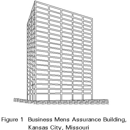
The trend in tall building design after the mid-1950's was to provide larger open spaces with longer spans and simpler facades with a clearly perceptible column grid. The influence of Mies van der Rohe, with respect to modularity of facades and structural frame expression, permeated tall building exterior architecture in the 1950's and 1960's. The frame expression was often simply and clearly depicted on the facade or in some cases, by special emphasis if highly articulated, as shown in Figure 1. The evolution of a modular metal and glass curtain wall not only gave rise to lighter enclosures, but also to non-integral window wall systems which were simply supported on the structure. The floor plan was divided into a grid pattern of regular bays in each direction and bay dimensions in the range of 7,5m to 10,5m were common. It should be noted that such Vierendeel frames were basically very inefficient for resisting wind forces since they could not rely on built-in encasements for some stiffening, and the structural premium for height was considerable. It was recognised that the shear-frame concept was uneconomical for structures over 25 storeys in height.
The idea that steel components can be assembled in various forms to constitute an overall three-dimensional system which can efficiently resist wind forces as a total system began to emerge in the 1960's. The main proponent of this design trend was Fazlur Khan who systematically pursued a logical evolution of high-rise systems based on the premise that different height ranges demand a new composition of steel framing to maintain a tolerable steel premium for height [2]. Many systems were devised, such as Truss-Frame Interacting Systems, Tubular Systems, Bundled Tubular Systems, Mixed Systems, etc. These structural developments, combined with the pervasive Miesian approach to the architecture of the time, resulted in an explosion of structurally oriented architecture in the 1960's and 1970's, which can truly be identified as the Structuralist phase. In terms of massing, simple rectilinear prismatic forms with flat tops were used for the most part. Simple form modulations included transforming the plan into the shape of a cross or some other simple form.
A trend in the last decade has been to design buildings that are shaped both in plan and profile in a variety of ways to respond to urban grid and subjective aesthetic criteria. Often the facade architecture has reference to historic buildings of the turn of the Century with their masonry expressions and profile setbacks. Varieties of stone cladding and combinations of stone and precast concrete and other materials have evolved. The facade architecture is often compositional in nature (with the slides, consider including Philip Johnson's 'Chippendale' architecture - AT & T Building, New York (1978-83)) with respect to colour, texture and adornments. Geometric forms have involved not only overall shaping, but also local undulations related to bays or projections. All these developments have suppressed the Structuralist form of facade architecture in all but a few special cases. The structural systems approach has taken on an aspect of "mix and match" where pieces or parts of structural systems are blended to create an overall system to fit the peculiarities of a certain form [3].
A brief discussion of the generic high-rise steel systems is given below followed by some consideration of the design of ultra high-rise systems. The system descriptions are conceptual in nature.
The height ranges (number of storeys) referred to in this Lecture for the various framing options relate to American practice and American site dimensions. As slenderness is a significant parameter, the width of the building should be taken into account in assessing the suitability of a particular bracing option for a building of a given height.
The steel systems developed between 1960 to 1975, fit a logical evolutionary pattern with one development leading to another, each new system being a link in the process[4]. Although the primary motivation for these developments was structural efficiency, the systems offered great opportunities for Structuralist facade architecture.
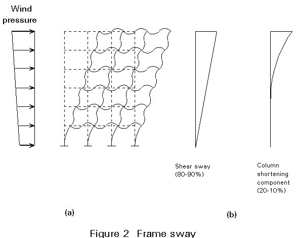
Shear frames or Vierendeel frames, in which beams and columns are rigidly connected to provide moment resistance at joints, are placed in two orthogonal directions to resist wind forces in each direction. Each frame is required to resist its proportion of the wind shear, which is determined on the basis of its relative stiffness compared to the total. The efficiency of development of lateral stiffness is dependent on bay span, number of bays in the frame, number of frames and the available depth in the floors for the frame girders. Bay dimensions in the range of 6m to 9m are commonly used. In these shear frames, the predominant contribution to sway deflection under wind load comes from the bending of beams and columns due to the wind shear and to a smaller extent, from column shortening or the cantilever component (Figure 2). The design of these frames is controlled therefore by the bending stiffnesses of individual members. The deeper the member, the more efficiently the bending stiffness can be developed.
When the frames are regularly spaced in both directions, a rectilinear column grid is created which is suitable for rectilinear plan forms. The architecture of these buildings has centred on bay or frame expressions. An outstanding example of this expression is in the Business Mens Assurance Building, Kansas City - a 20-storey structure built in about 1960 (Figure 1). Frames can be placed at other angles or on an irregular basis to create various plan shapes to fill the area of an irregular site. Shear frames can also be placed only on the exterior faces instead of using a grid arrangement of frames.
In current practice, buildings with pure shear frames are generally restricted to only a few storeys in height, since other more efficient forms are available. However, the uncluttered rectilinear Vierendeel form may still be preferred in cases where other forms involving diagonals or trusses may interfere with architecture and space planning. The basic inefficiency in shear frame buildings arises from the need for moment-connected rigid joints which are expensive to fabricate, in addition to the steel quantities involved. The optimization of frames in a practical sense has centred on minimizing the number of such joints, replacement of field welding by field bolting, and similar criteria.
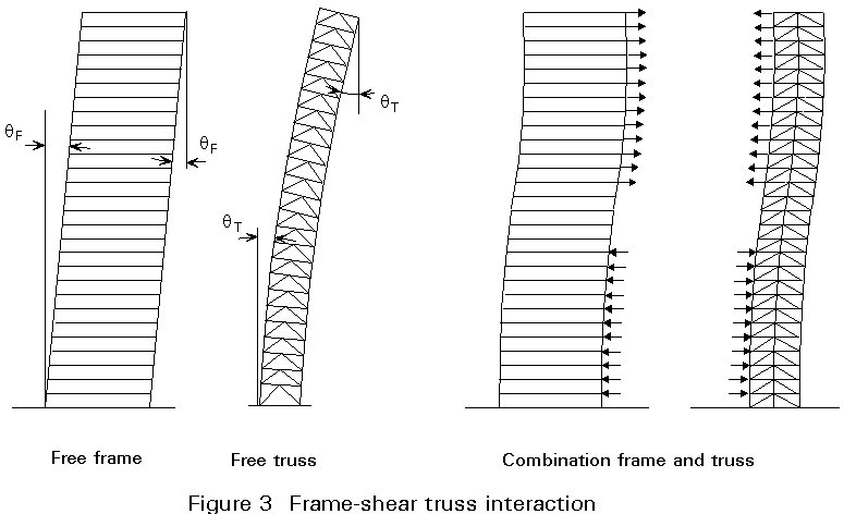
Shear trusses can be provided in the vertical direction, if the organisation of the core permits such an arrangement. In general, building core elements including elevator banks are centralized and will permit core trusses connecting columns in at least one direction. These trusses combined with perimeter shear frames produce a Shear Truss and Frame System (Figure 3). There may be other interior frames which participate as well. This type of interacting system has a wide range of application in structures from 10 to 40 storeys. In smaller buildings, the frame component may be eliminated, with the result that all wind forces are resisted by the core trusses only. In some isolated instances, braces have been provided in both directions. Particular coordination with respect to providing access into the core needs then to be considered. The combination of the Shear Frame and vertical braces produces interaction of two modes of behaviour, that of a Shear Frame and a Cantilever (Figure 3). This combination produces desirable results in the stiffness efficiency of the overall system.
Vertical trusses resist wind forces as a cantilever and therefore provide lateral stiffness more efficiently than shear frames. However, the depth available to the truss, which is dependent on the planning of the core area, determines the overall effectiveness of the system. For the truss bracing K-forms, X-forms or single brace forms can be used. The K-form is commonest since the bracings do not participate extensively in carrying gravity load, and can thus be designed for axial forces due to wind without gravity axial forces being a major consideration. In the X and single brace forms, gravity axial forces may dominate in the design of braces.
In general, Shear Truss and Frame Systems produce the most economical steel structural system for buildings up to 30 storeys in height.
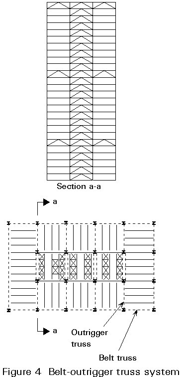
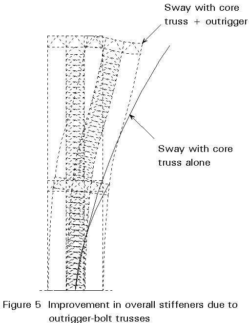
The exterior fascia shear frames and the vertical trusses in the core can be tied together by a system of outrigger and belt trusses which are provided at plant room levels, where the trusses will not interfere with the interior space planning. Figure 4 shows the arrangement of trusses. The primary result of the outrigger trusses is the development of axial forces in the exterior columns due to wind action. This behaviour significantly improves the lateral stiffness under wind forces. The use of belt trusses on the facades, at the same level and perpendicular to the outrigger trusses, further enhances participation of exterior frames in the cantilever behaviour. The belt trusses transform the two-dimensional frame system into a three-dimensional frame system which resists wind action. The building sway under wind is significantly reduced by the introduction of these trusses. A review of the deflection curve indicates two stiffening effects: one related to the participation of the external columns in a total-building-width cantilever mode; the other related to the stiffening of the facade frame by the belt trusses. Improvements in overall stiffness of up to 25% can result as compared to the Shear Truss and Frame System without such outrigger-belt trusses (Figure 5). The effectiveness of the system depends on the number of trussed levels and the depth of the truss at each level.
The accompanying slide set provides illustration of the first Wisconsin Centre, Milwaukee, a 42-storey building framed in this fashion.
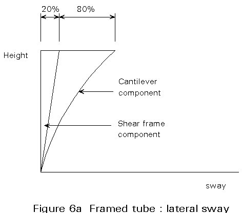
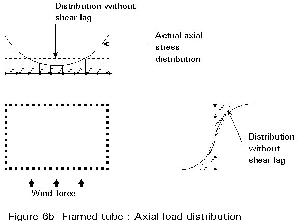
If the facade shear frame is made stronger by closer spacing of columns and larger member proportions and if such frames are continuous at corners, the overall frame is transformed into a cantilever Framed Tube fixed at the ground. The effectiveness of the cantilever depends on the minimization of the part of the sway deflection due to the shear frame. One basic objective is to reduce this component to less than 25% of the total sway so that the predominant deformation is that of a cantilever (Figure 6a). When such frames are provided on all four faces of a tower, one obtains a hollow tubular configuration. This 'silo' form containing small window perforations is most efficient in resisting wind forces. Figure 6b shows the distribution of column axial forces due to cantilever action. The more the distribution is similar to that of a fully rigid box with uniform axial stress on the flanges and triangular distribution on the webs, the more efficient the system will be as a cantilever. The Framed Tube system was first introduced in the mid-1960's in reinforced concrete. The dense grid exterior structure was readily formed, creating the appearance of a punched tube. This system was adopted later for steel buildings.
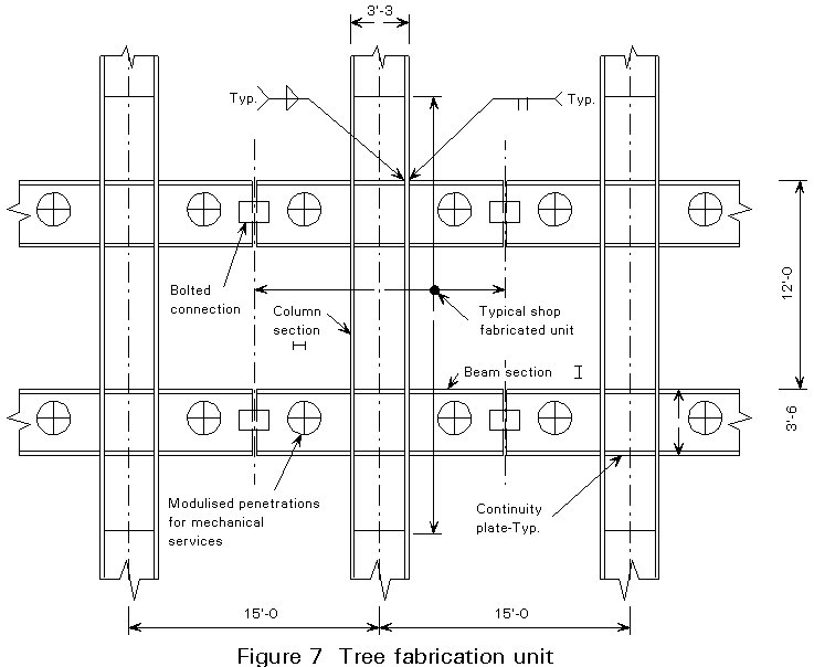
The proportions of the Framed Tube require wide members for both beams and columns, and they need to be rigid at the joints. In concrete, the rigid joint is achieved by the use of in-situ concrete, whereas in structural steel, the joints need to be welded for rigidity and the members built-up for larger widths. The use of a prefabricated Framed Tube "Tree" element (Figure 7) where all welding can be done in the shop in a horizontal position has made the steel Framed Tube more practical and efficient. The "Trees" are then erected by bolting at mid-span of the beams. Considerable speed of construction of the order of 3 to 4 storeys per week can result if "Trees" are used.
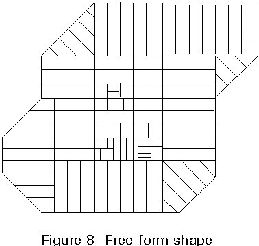
Steel Framed Tube buildings involve column spacings of 3m to 5m on the exterior which can be transferred or transitioned into wider spacings, if required, at the lower storeys to integrate street level activities. Such tubular systems have been used extensively for structures of 30 to 110 storeys in height. An outstanding example is the World Trade Centre in New York. Tubular systems are generally adaptable to prismatic vertical profiles. For varying vertical profiles and buildings involving significant fascia offsets, the discontinuity required in the tubular frame to achieve the shape introduces serious disadvantages. The system can however, be readily adapted to a variety of non-rectilinear plan forms.
Figure 8 shows a particular plan configuration that has been used as a Framed Tube. Provided the proportionality of the elements of the tubes is maintained, any closed overall form can be used as a Tubular system.
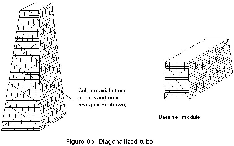
The most efficient structure acting as a cantilever is the exterior Diagonalized system. This system was first introduced in the John Hancock Centre in Chicago, a multi-use, 100-storey structure (Figure 9a).
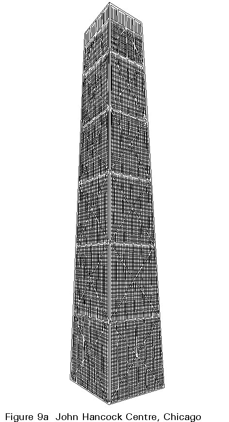
The system is essentially a Trussed Tube with the fascia diagonals not only acting as a truss in the plane, but also interacting with the trusses on the perpendicular facades to develop the tube action (Figure 9b). A principal advantage of the Trussed Tube is that it eliminates the need for the closely spaced columns of a framed tube. In the John Hancock Centre, the column spacing on the broad face is 12,2m and on the short face, 7,62m. Another advantage of this Tube is that the interior is free from structure for resisting wind action. The Tube is therefore, most suitable for multi-function buildings. Additional interior columns, as required, and simple floor framing complete the system [5]. The 100-storey, 337,5m high John Hancock structure required only 141,8 kg of steel per square meter of gross area of floor. The design of most members was controlled by gravity forces rather than wind forces. Simpler fabrication and erection techniques resulted from shop fabrication of joints and field bolting. The clear disciplined structure set the basis for the overall exterior architecture of this building.
The system is most efficient in a single exterior closed form, especially when in a rectilinear shape. It is not readily adaptable where interior tube frame lines are present, In some special cases, the interior diagonals can be organised to suit specific office layouts. The principal of fascia diagonalization can be readily used for partial tubular concepts. For instance, in long rectangular buildings, the end frames on the short face may be diagonalized, where the long face is a Shear Frame. The end diagonalized frame may be in the form of a channel or "C" shape to provide wind resistance in both directions. The diagonalization can also vary from a broad "X" form to smaller "X's", thus transforming each facade into a diagrid braced system. Many variations are possible, each having its own impact on the exterior architecture.
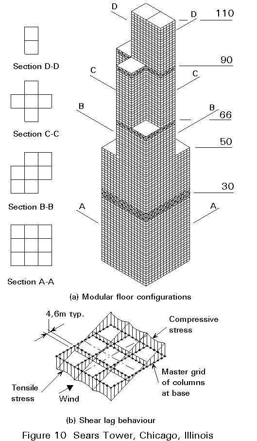
The need for vertical modulation in a logical fashion has created a variation of the tubular structure based on clustering or bundling of smaller sized tubes, each of which rises to a different height. This variation is typified by the bundled tube system of the Sears Tower in Chicago, Figure 10. This building has brought about a new generic form of structure called the "Bundled Tube" [6]. In the Sears Tower, the Bundled Tube is composed of 22,86m square modules, and nine modules are lumped together to form the total system, as shown in Figure 10. These tubes rise to different heights and are terminated when they are no longer needed architecturally and structurally. The walls of the tube are formed by columns at 4,57m centres and deep frame beams at each floor. The introduction of Framed Tube lines on the interior greatly reduced the influence of the "shear lag" effect that is present in exterior tubes of large side dimensions (Figure 10). The intent of the system was not only to create a powerful structural system, but also to create vertical modulation in a logical fashion. The development of a variety of floor sizes and shapes in the same building is considered a positive asset from the point of view of marketing real estate.
The modularity and the conceptual basis of the Bundled Tube have a broad application. The cells or tubes can be arranged in a variety of ways to create different massing. It can be applied to 30 storeys as well as to ultra-tall structures. Further, the shape of each tube itself can be changed to any other closed clustered shape. Triangular and hexagonal units have been used in some existing applications.
Two recent examples of the application of the Bundled Tube principle are worth noting. One is the Crocker Centre in Los Angeles which involves two towers, 57 and 47 storeys in height. The site conditions together with considerations of the sculptured form resulted in a shape which included a square tube and a triangular tube, as shown in Figure 11a. A column spacing of 4,87m was selected for the Tubular system. A significant advantage of the Bundled Tube system is the enormous torsional resistance which is helpful in absorbing torsional lateral forces due to asymmetry. In this case, the torsional loads were generated both by wind and seismic forces.
The Framed-Tube buildings that have hitherto been adopted in wind controlled environments are now being adapted to seismic designs, such as the Crocker Centre. Apart from meeting wind deflection and stress criteria, the detailing of members and connections for ductility and an appropriate sequence of plastic hinge formation is required. Higher tubular efficiencies result from deeper beam members. However, this advantage has to be balanced with the strong-column, weak-beam principle to assure plastic hinges in the beam element. Other items include panel zone areas which need to be reinforced with doubler plates.
The 75 storey, 296m high Allied Bank Tower in Houston is another example of the Bundled Frame Tube application. The shape is formed by two quarter circles placed anti-symmetrically about the middle tubular line, see Figure 11b. The column spacings are 4,57m with the usual "tree" type construction. The system also uses two vertical trusses in the core which are connected to the exterior tube by outrigger and belt trusses. Significant improvement in tubular behaviour is obtained because of the participation of the trusses. This system, therefore, embodies elements from the Framed Tube, Bundled Tube and Truss systems with belt and outrigger trusses.
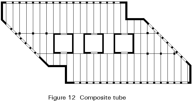
Mixed Steel-Concrete systems are now a well established new system that can be used as readily as either steel or concrete systems for high-rise buildings [7]. Such mixed systems which involve reinforced concrete and structural steel components in forms that are generally applicable, such as the Composite Tubular system, and Concrete Core Braced systems, have been widely used. Composite structures in a true sense, they have liberated the traditionally rigid discipline of either steel or concrete elements. The properties of concrete that are most attractive are its rigidity and its ability to be cast into different types of structural elements. Therefore, most mixed systems rely on concrete for lateral load resistance. Shear wall elements and/or punched wall or framed-tube elements with monolithically cast beam-column joints are of higher strength concrete. Concrete has extended the application to structures of 50 to 80 storeys in height. Concrete strengths of 40N/mm2 to 55N/mm2 are commonly used, but in some cases, strengths up to 95N/mm2 have been used. The floor framing is of steel in mixed systems, which is advantageous because of the ability to span longer distances with lighter members. Thus larger column-free spaces are possible.
The first Canadian Centre in Calgary, Canada consists of two towers and a 10-storey banking pavilion, located on an L-shaped site. The two towers are 64 and 43 storeys in height. A sculpted form which provides diagonal vistas to mountains and the city was highly desirable for this prominent corner site. Each tower is similarly shaped, basically involving a parallelogram with truncated and re-entrant corners. The structural concept is based on a tube-in-tube concept involving an exterior reinforced concrete framed-tube and an interior shear wall core tube. Structural steel floor framing and other interior steel columns complete the system, as shown in Figure 12. The Tube system on the exterior is a combination of Framed Tube of beams and columns with solid walls at the corners.
In contrast to exterior Tubular systems, Core Braced Systems resist wind forces by shear walls in the core. Core walls for wind resistance have been utilized quite extensively in concrete buildings. The closed tube shape is then in the interior with access penetrations into the core. This type of core element can be used in a steel frame to form the Core Braced Steel system. Since all wind forces are resisted by the concrete core, the steel components need only be connected non-rigidly to resist gravity forces. In conventional buildings, the overall size of the core wall tube is limited by the dimensional requirements of the core elements. However, it may be possible in some cases to evolve a larger wall system that will be suitable for buildings in the range of 50 to 80 storeys as illustrated below.
Figures 13a and 13b show an arrangement of cores for a 75-storey structure which required considerable flexibility in exterior shaping with offsets and setbacks. A lighter, non-rigid structure in steel on the exterior allowed this flexibility. The Core Wall Tube system was planned with four inter-connected pods encasing an atrium in the lower part and an octagonal shaped core in the upper parts. This simple arrangement of walls and cores allowed maximum efficiency of the wall system for the structure and maximum flexibility for exterior architecture.

As the height of a building increases, the ability to resist lateral forces becomes the predominant structural design criterion. The major design criterion is the provision of enough lateral stiffness to limit wind sway and to limit occupant motion perception to acceptable levels. The motion of the building is essentially dynamic and all factors that affect this dynamic behaviour need to be considered. The structural parameters are stiffness, damping and mass. Among the non-structural parameters is the aspect of aerodynamic shaping of the building which will have a significant effect, especially in ultra-tall structures. Two wind effects are to be recognized. One is down wind behaviour, which is influenced by the drag parameters of the shape, and the other is the cross wind behaviour influenced by the uniformity of the vortex shedding inherent in the shape. While the basic design requirement of controlling lateral sway still predominates, overall shaping of the form becomes equally significant. The architecture of the shape must then be suitably integrated with its structural aspects to produce an optimum economic balance.
Superframes or Megaframes assume the form of a portal which is provided on the exterior of a building. The frames resist all wind forces as an exterior tubular structure. The portal frame of the Superframe is composed of vertical legs in each corner of the building which are linked by horizontal elements at about every 12 to 14 floors. Since the vertical elements are concentrated in the corner areas of the building, maximum efficiency is obtained for resisting wind forces. The vertical legs and the horizontal links are themselves frames with large dimensions in the plane of the frame [3].
Inherent in the concept of a Superframe is the ability of the system to accommodate varieties of spaces suitable for multiple functions. Historically, tall buildings which have multiple functions in a single building require flexibility of spaces. Structures, such as the John Hancock Centre in Chicago, have successfully accomplished this flexibility. Ultra high-rise Megastructures will need to further the idea of flexible space or modular spaces, where each space can be planned efficiently for its own use and inserted into a Megaframe. Superframes allow this modularization of space to occur with maximum freedom from structural encumbrance. Portal apertures on the exterior wall allow freedom of expression for each unit and also provide access for daylight. Figure 14b indicates an arrangement of interior spaces with an atrium in each space module.
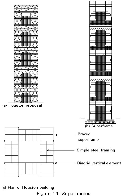
The structural efficiency is obtained from the concentration of material close to the corners. Each of these vertical legs is required to be stiff in its own plane. The legs then take the form of a diagonalized truss chord. The corner truss legs need strong horizontal connections at frequent modular intervals to make them function together like an equivalent cantilever. The horizontal members, therefore, will need to be equally stiff, and are diagonalized as well. The net effect of this combination would be to produce an equivalent cantilever structure as effective as a Tubular system. An appropriate diagonalization of structure is represented by an overall modularized diagrid frame, in which the structural members within the portals are removed (Figure 14a). Figure 14a also shows the adoption of the Superframe concept to an 80-storey structure in its simplest rectilinear form. The effect on the exterior architecture and the potential possibilities can be clearly observed. While the example illustrates a rectilinear form, the concept can be used for other forms where the principle of stiffnesses of horizontal and vertical elements and their inter-connections are met.
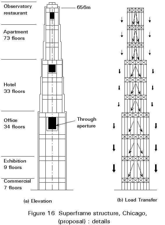
Figure 15 shows a study of a Superframe concept applied to a 170-storey, 655m tall tower involving 706.000 sq. metres of floor space. The multiple functions involved are indicated in Figure 16a. The tower form, step-tapered from 88m x 88m at the base to 44m x 44m at the top denotes the functional needs of space. The basic structure, Figure 15, involved telescoping Superframes, not only to fit the overall geometry of the shape, but also to augment the structural stiffness. The curtain wall was constructed over the general structural form and involved many more smaller offsets. A significant innovation involved the provision of through-apertures in the building to reduce aerodynamic oscillations. Their effectiveness was confirmed by wind tunnel testing. The equivalent dampening effect of this aerodynamic shaping illustrates the need for such design coordination in supertall structures. The significant aspects of this structural design were:
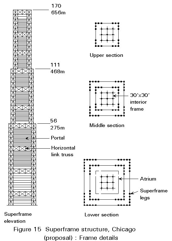
i. Telescoping of the Superframes allowed an orderly transition of the structure and the needed lateral stiffness.
ii. The aerodynamic behaviour was greatly assisted by the apertures which reduced the cross-wind accelerations and forces due to vortex shedding by as much as 25%. The overall tapered form assisted as well in reducing the wind 'sail' area gradually toward the top.
iii. The structural system efficiency was enhanced by the sequential load transfer from the interior to the exterior, as shown in Figure 16, so that all gravity loads were carried by the Superframes.
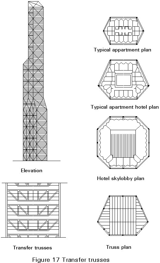
The general concept of the exterior Trussed Tube can be extended to ultra high-rise structures involving multiple functions. Figure 17 shows a 135-storey exterior Trussed Tube, which was submitted for a project competition in New York. This slender form, having an aspect ratio of 10 to 1, involved approximately 185.908 sq. metres of floor space. The arrangement of multiple functional spaces is indicated in the plans. The horizontal and vertical facets of the shape were modulized so that a triangular shaped framing could be used without discontinuities. This framing resulted from the concept of a tetrahedrally framed solid form where all the non-essential elements were eliminated to create the tube and the external shaping of it. In order to express the purity of the structure, the window wall was placed a certain distance behind the truss, creating an open truss trellis on the exterior. This open form has the effect of eliminating overall wind vortex formation and would significantly reduce cross-wind oscillations. This is another form of aerodynamic shaping to mitigate wind effects. The internal structure is supported on 3-storey tension truss elements which span across the tube thereby eliminating the need for internal columns (Figure 17). This arrangement allowed the use of gravity steel in the development of lateral stiffness and wind load resistance. It also made it possible to deal with the effects of temperature contraction of the exposed, but clad exterior columns.
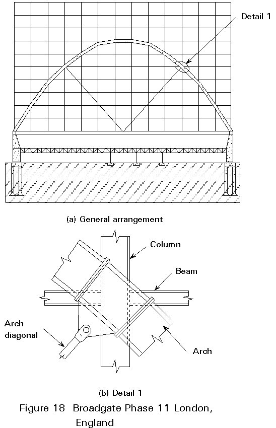
The beauty and essence of exposed steel can form the basis for exterior architecture as has been illustrated in the Hong Kong-Shanghai Bank in Hong Kong and the Pompidou Centre in Paris. Exposure of steel on the exterior needs to address the issues of fire and corrosion protection. Corrosion protection has been attained, in some cases, by the use of weathering steels and, in others, by the use of durable, long-life, fluor-carbon paint systems. For fire resistance, liquid filled members have been used on occasion. An outstanding example is the US Steel Building in Pittsburg. The analytical fire engineering methods now available permit exposed steel system to be more readily designed. Such an approach was used for Phase 11 of the Broadgate Project recently completed in London. The 10-storey office building spans 78m over railroad tracks and its design was based on a tied arch solution (Figures 18a and 18b). This classic structure clearly expresses the steel through its articulated members and joints. It stands as a symbol for what is possible in exposed steel architecture.
× Shear frame systems
× Shear truss-frame interacting systems
× Vertical trusses, and belt and outrigger trusses
× Framed tubes
× Diagonalised tubes
× Bundled tubes
× Modular tube systems
× Mixed steel - concrete systems.
[1] Mujicha, Franciso, "History of the Skyscraper" Archaeology and Architectural Press, 1929, Copyright, 1930 by Mujicha, Property of the American Institute of Steel Construction.
[2] Khan, Fazlur, R., "Structural Systems for Multi-Storey Steel Buildings".
[3] Iyengar, H., "Steel Systems for High-Rise Buildings", International Conference on Steel Structures, Singapore, March 1984.
[4] Iyengar, H., "preliminary Design and Optimization of Steel Building Systems", State of the Art Report No. 3, Technical Committee No. 14: Elastic Design, American Society of Civil Engineers-International Association for Bridge and Structural Engineering Joint Committee on Tall Buildings, August, 1972.
[5] Iyengar, H., "Structural Systems for Two Ultra High-Rise Structures", Australian and New Zealand Conference on Planning and Design of Tall Buildings, Sydney, Australia, May, 1973.
[6] Iyengar, S. H. and Khan, F., "Structural Steel Design of Sears Tower", Conference on Steel Developments, Australian Institute of Steel Construction, Newcastle, Australia, May, 1973.
[7] Iyengar, Hal, "Recent Development sin Composite High-Rise Systems", Council on Tall Buildings and Urban Habitat, Monograph, Advances in Tall Buildings, 1986, Council on Tall Buildings and Urban Habitat, Meeting, Chicago, Illinois, October, 1982.