ESDEP WG 14
STRUCTURAL SYSTEMS: BUILDINGS
To provide definitions that make it possible to point out the essential characteristics of a framed structure. Attention is given to joint behaviour and to the problem of the choice of structural model depending on the loads acting on the structure.
Lecture 7.11: Frames
Lecture 11.6: Moment Connections for Continuous Framing
Lecture 11.7: Partial Strength Connections for Semi-Continuous Framing
Lecture 14.9: Methods of Analysis for Multi-Storey Frames
Lecture 14.10: Simple Braced Non-Sway Multi-Storey Buildings
Lecture 14.13: Design of Multi-Storey Frames with Partial Strength and Semi-Rigid Connections
Lecture 14.14: Methods of Analysis of Rigid Jointed Frames
The following subjects are discussed:
In particular the differences between braced and unbraced frames are analysed as well as the differences between sway and non-sway frames. The different behaviour of connections of structural members (girders, columns and bracings) is considered, in order to define the behaviour of rigid and semi-rigid frames.
Before discussing rigid jointed frames, some definitions are introduced since the same meaning is not always associated with the same words in different countries. It is necessary sometimes also to define the structure in a particular manner in order to use conventional simplified analytical models in the analysis and design of the structure.
The evolution of computer methods and hardware in fact allows any type of analytical evaluation, e.g. elastic and inelastic analysis including any type of inelastic model and of imperfection, to be undertaken. It might be said therefore that it is not necessary to go through definition of systems and to simplify models of analysis. For a braced frame, for example, it is not necessary to separate frame and bracing behaviour since both can be analysed with one computer model. On the other hand, simple models are useful for preliminary design and for checking computer results in the design office.
The definitions below describe what is meant by a bracing system, what a framed system represents and when a framed system can be considered to be braced by another system. Sway and non-sway frames are defined. An explanation of why a braced frame is often considered equivalent to a non-sway frame is given.
In all these cases the following steps are followed:
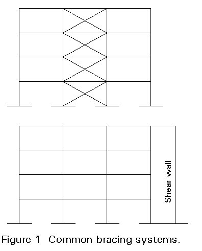
In common design practice and in design guides and manuals, bracing systems are very often identified with triangulated trusses or with concrete cores or shear walls which are present in buildings to accommodate shafts and staircases. It is very common to find bracing systems represented as shown in Figure 1.
This assumption is based on engineering common sense which tends to represent reality in an average sense without referring to more general and mathematical definitions which would include all the possible cases.
The simplification of representing a bracing system by a triangulated truss also arises because in steel structures, in contrast to concrete structures where all the joints are naturally continuous, the most immediate way of making connections between members is to hinge one member to the other. As a result structures are created which need bracing systems in order to prevent failure mechanisms forming. Based on this simplifying consideration, all the joints of Figure 1 can be assumed to be hinged. Therefore bracing can only be obtained by use of triangulated trusses or concrete cores or, exceptionally, by a very strong frame.
There are several reasons for having hinged connections in the steel system:
a. from the point of view of ease of fabrication and erection, it is more convenient simply to join the webs of the members without connecting the flanges.
b. it is simpler to use bolted connections which do not need the deformations in the connections to be minimised.
c. from the design point of view there is a dramatic simplification in the calculations if the resisting systems can be separated into systems resisting vertical actions and systems resisting horizontal actions. In addition, if all the girders are hinged to the columns, the sizing of the simply supported girders and the columns is a simple task.
d. from the economic point of view, it is more convenient to reduce the horizontal drift by means of bracing systems added to the hinged construction than to use framed systems with rigid jointed connections. This consideration is even more important for steel structures with reinforced concrete cores where the core itself can act as the bracing system.
In conclusion, a topological definition of a bracing system equates a bracing system to a triangulated truss or to a shear wall. This definition covers the majority of actual cases but is not sufficient to clarify the function of a bracing system. For this purpose a definition based on the requirements of a bracing system is provided below.
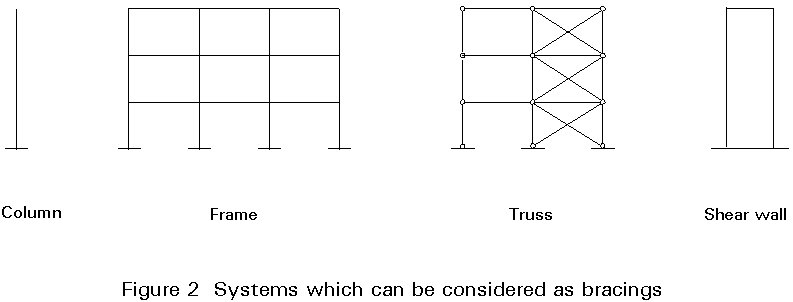
A bracing system can be defined as a structural system capable of resisting horizontal actions and limiting horizontal deformations. On the basis of this definition, all the systems shown in Figure 2 can be considered bracing systems. Within one building more than one of these systems can be present. In that case some systems are more effective than others in resisting horizontal loads, the others are neglected.
The definition allows a simple frame, and even a column, to be considered as a bracing system. The column or the frame may not have enough strength or stiffness to resist the horizontal actions with reasonable sizing of its members (columns and girders) and then to satisfy the strength and serviceability checks which require limited interstorey and global drifts. In this case it is necessary to add other bracing systems to the frame itself.
When the words "bracing system" are used in the Eurocode, they refer to a system for preventing lateral instability of beams or compression members and a triangulated truss is shown as an example, see Fig. 5.2.5 of Eurocode 3 [1].
According to 5.2.5.1 bracing systems may be triangulated frames, rigid-jointed frames or shear walls/cores, see Figure 2.
In common practice, (continuous) framed systems are considered to be assemblies of beams and columns in which all the joints are completely continuous. In contrast truss or simple framed systems are those in which all the joints can be considered hinged.
A purely rigid jointed frame system is characterised by joints between frame members and by no additional bracing system. The frame itself has to resist all the actions, vertical as well as horizontal. At the same time, it has to provide the required stiffness to the structure in order to limit deformations within the allowable values. Even though the detailing of all the connections results in a less economic structure, framed systems have some benefits:
a. the connections are more ductile and therefore the structure performs better in earthquakes.
b. from the architectural and functional points of view, it can be advantageous not to have any triangulated truss in the structure.
Actual structures do not always fall into the two categories defined above. Connections themselves actually behave semi-rigidly and therefore the hinged and framed conditions are only idealisations. An engineering definition is needed to define when a semi-rigid connection can be assumed to be hinged and when it can be assumed to be rigid.
The practice in different countries in the design of connections and framed systems varies. The approaches used are different in different parts of the world. In some countries, e.g. USA, the concept of semi-rigid connections dates back to the 1930's when the first studies on semi-rigid riveted connections were carried out by Johnston. In these countries also the code allows the use of semi-rigid connections (type 3 connections) and introduces the concept of wind design (type 2 connections). In wind design the connection is assumed to be capable of transmitting only part of the bending moments (those due to the wind and not those due to vertical loads).
The approach of semi-rigid connections, in use for several years, is also adopted, for example, in UK, Australia, Canada, and Netherlands. In other countries, e.g. Italy, France, Spain, Greece, these concepts have not been introduced and therefore semi-rigid connections are not widely adopted although they are included in Eurocode 3 [1].
To determine whether a system can be considered continuously framed or not, the effects of the connection on the frame behaviour has to be considered, taking into account that the ideal condition of hinged or rigid connection does not correspond to reality. These effects are not for immediate evaluation since the behaviour of the frame can be different depending on what is being considered:
In some cases the strength of the connection is the important consideration whilst in other cases the flexibility of the connection plays a major role. Sometimes the elastic behaviour of the connection is sufficient to determine its effects on the behaviour of the frame whilst in other cases the complete inelastic behaviour of the connection is needed for evaluating frame effects.
These cases cannot be fully covered in this lecture. Study of the other Lectures 14 will give a more complete view of the different aspects. In recent years this subject has been given much attention from research devoted either to the analytical and to the experimental aspects. In the remainder of this lecture the effects on frame behaviour are described and some indicative values for connection characteristics are suggested as a basis for assuming a system as a rigidly jointed frame.
A connection between two or more different members has to transmit all the internal actions through the members, i.e. axial load, shear load and bending moment in the case of a plane frame.
However, the term "semi-rigid connection" is only used to refer to the bending flexibility in the discussion below.
In Figure 3, taken from [4], connection behaviour is shown qualitatively by definition of the regions in which the connection can be assumed as hinged flexible or semi-rigid. This qualitative representation suggests that fully welded connections, extended end plate, and top and bottom flange splices could be considered as rigid restraints.
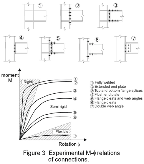
The results of computer analyses for portal and multi-storey frames with semi-rigid connections, with respect to the elastic critical load of the frame, are given in [5].
For partial strength semi-rigid connections, some results [5] indicate that, for rigid jointed frames, within the ranges indicated before, some degree of flexibility can be allowed, but no partial strength is advised. Partial strength connections are considered to be within the semi-rigid or flexible range.
In Eurocode 3 [1] it is first stated, within the Design Assumptions (5.2.2), that:
"the assumptions made in the global analysis of the structure shall be consistent with the anticipated type of behaviour of the connections".
Then, in 5.2.2.2, simple framing is defined for frames where the connections between the members may be assumed not to develop moments. In the global analysis, members may be assumed to be effectively pin connected.
Further, in 5.2.2.3, when continuous framing is defined, it is stated that:
"Elastic analysis should be based on the assumption of full continuity, with rigid connections which satisfy the requirements given in 6.4.2.2".
The same statement is given for the other methods suggested for the analysis, i.e rigid plastic and elasto-plastic. These methods are discussed further in Lecture 14.14.
In 6.4.2.2, when rigid connections are defined, the following principle is given:
"A rigid connection shall be so designed that its deformation has no significant influence on the distribution of internal forces and moments in the structure, nor on its overall deformation".
The application rules provided state:
"The deformation of rigid connections should be such that they do not reduce the resistance of the structure by more than 5%".
When beam-to-column connections are classified, in 6.9.6.2 first it is stated that:
"A beam-to-column connection may be classified as rigid or nominally pinned on the basis of particular or general experimental evidence, or significant experience of previous satisfactory performance in similar cases or by calculation based on test evidence".
Then, the following is suggested as an application rule:
"A beam-to-column connection in a braced frame, or in an unbraced frame which satisfies the condition specified in (5), may be considered to be rigid compared to the connected beam, if the rising portion of its moment characteristics lies above the solid line on the appropriate diagram of Fig. 6.9.8. of Eurocode 3" (Figure 4).
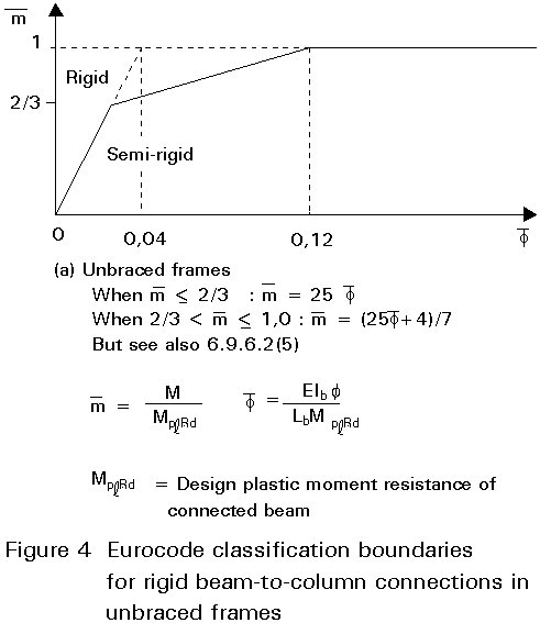
This rule suggests that, in order to have the moment-rotation curve of the connection lying above the solid line, it has to result, for values of < 2/3 (which means for values of the moment M smaller than 67% of the plastic beam moment MplRd), K has to be greater than 25. In fact (see definitions in Figure 4):
K = ![]() > 25
> 25
This value of 25 guarantees the stiffness characteristic of the connection. Some other requirements are also given in order to ensure sufficient strength. The fact that the entire moment-rotation curve has to be above the solid line indicates that the entire nonlinear curve of the connection is to be checked.
The further requirement for unbraced frames, given in Clause (5) of 6.9.6.2 of Eurocode 3, discussed below, is somewhat cumbersome. The meaning of this requirement is that, for unbraced frames, the beams must have an adequate stiffness otherwise the frame will be too flexible, even with rigid connections. This consideration is obvious for an engineer who knows which typology to choose for each case. However, since all the serviceability and ultimate limit states have to be satisfied, this requirement might be considered automatically fulfilled.
Clause (5) states:
"The line given in Figure 6.9.8(a) (Figure 4 of this lecture) for unbraced frames may be used only for frames in which every storey satisfies:
Kb / Kc > 0,1
where Kb is the mean value of Ib/Lb for all the beams at the top of that storey
Kc is the mean value of Ic/Lc for all the columns in that storey
Ib is the second moment of area of a beam
Ic is the second moment of area of a column
Lb is the span of beam
Lc is the storey height of a column.
In Section 2 the requirements of a bracing system are described and a common definition is given. Sometimes the term "bracing system" is inappropriately identified with the term "braced frame". It is clear that the definitions of the two terms are different. The word "braced" in the second case is used as an adjective to the word "frame" and therefore at least two structures have to be identified: a bracing and a frame.
A braced frame is commonly intended as a frame to which a triangulated truss is attached. The fact that in reality there is no clear cut distinction between hinged structures with bracing systems and purely rigid jointed framed structures calls for a more exact definition which allows distinctions to be made between:
For the first three types reference should be made to Sections 2 and 3 above. The definition of braced frames is discussed below.
The main function of a bracing system is: to resist horizontal actions, and is derived from the separation of the resisting systems: vertical and horizontal. In some cases the vertical system also has some capability to resist horizontal actions. It is necessary therefore, from an engineering point of view, to identify the two sources of resistance and to compare their behaviour with respect to the horizontal actions. Sometimes this identification is not obvious since the bracing is integral within the frame and therefore there is only one structure. However, even in this case, it is possible to make some assumptions in order to define the two structures to be compared. The examples given below clarify these concepts.
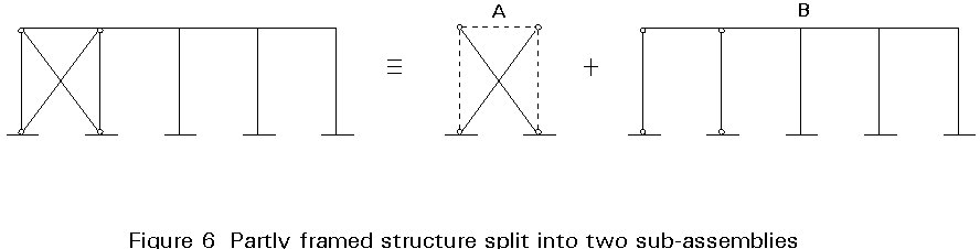
Figures 5 and 6 represent structures in which it is easy to define, within one system, two sub-assemblies which identify the bracing system and the system to be braced. In particular, a structure is shown in Figure 5 where there is a clear separation of functions: the horizontal loads are carried by the first hinged sub-assembly (A) and the vertical loads are carried out by the second one (B). In Figure 6, in contrast, since the second sub-assembly (B) is able to resist horizontal actions as well as vertical actions, it is necessary to assume that practically all the horizontal actions are carried by the first sub-assembly (A) in order to define this system as braced. In this case the first sub-assembly is defined as a bracing system if its lateral stiffness expressed by the spring constant Ka is considerably higher than the one of the second sub-assembly Kb (in this case a braced frame or system):
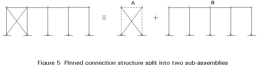
Ka » Kb (1)
This relation can be easily applied to the system of Figure 5 since the constant Kb is equal to zero and therefore the relation is certainly satisfied. For the system in Figure 6, the stiffnesses of both sub-assemblies have to be calculated and compared.
The following definition is provided in 5.2.5.3 of Eurocode 3 [1]:
"the frame can be classified as braced if the bracing system reduces its horizontal displacement by at least 80%"
which means that the stiffness of the two systems have to be compared and the following relationship satisfied:
Ka > 0,8 (Ka + Kb)
or
Ka > 4 Kb
Before defining sway frames and non-sway frames, it is useful to note the common design practice for evaluating safety of structures against stability. It is often convenient to isolate the columns from the frame and treat the stability of columns and the stability of frames as independent problems. For this purpose it is assumed the columns are restricted at their ends from horizontal displacements and therefore are only subjected to end moments and axial loads as transferred from the frame. It is then assumed that the frame, possibly by means of a bracing system, satisfies global stability checks and that the global stability of the frame does not affect the column behaviour. This gives the commonly assumed non-sway frame. This approach has led to years of research spent in the field of behaviour of columns and beam-columns.
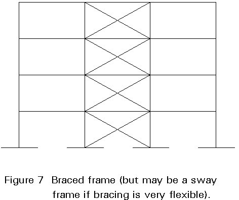
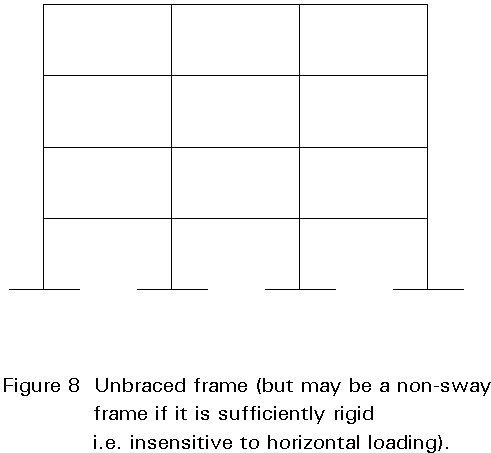
Design books, guidance documents, and even codes and recommendations, when speaking of stability of columns or stability of frames, commonly use the terms: "sway frames", "non-sway frames", "sway restricted columns" and "sway columns". To explain the concept of sway, as opposed to non-sway, figures such as Figures 7 and 8 are used. The frame of Figure 7 is considered to be the non-sway type and the one of Figure 8 is considered to be the sway type. This form of representation, which is based on common practice and common engineering sense, leads to the erroneous assumption that non-sway frames and braced frames are perfectly equivalent and therefore that one definition can be used instead of the other without causing any misunderstanding.
The equivalence between "braced" and "non-sway" frames cannot be established in general since the two terms refer to different aspects of the behaviour of the structure. The fact that the definitions of "sway" and "non-sway" appears when the problem of stability of columns and frames is evaluated suggests that these definitions are part of a simpler treatment of this problem.
The concept of braced and unbraced frames can be defined in engineering terms by means of comparison of the stiffness of the systems, as in previous sections, and has no straightforward implications for stability. The concept of sway frames is not intrinsic to the structure: it is based only on its mechanical properties.
In fact the seismic meaning of the term "non-sway frame" has no real significance. It is only valid in an "engineering" sense. There is no structure, braced or unbraced, in which there are no sway displacements. The displacements can only be small enough, for particular design purposes, to be considered equal to zero in an engineering sense.
Another reason for defining "sway" and "non-sway frames" is the need to adopt conventional analysis in which all the internal actions are computed on the basis of the undeformed shape of the structure. To make this assumption it is necessary that second order effects are negligible, i.e. no significant moments arise due to the action of vertical loads on the deformed shape of the structure. This definition can be shown to be equivalent to the previous one since the vertical design loads cause no significant moments if their value is not close to the elastic critical load of the structure.
When there is interaction between global and column behaviour, it is not possible to isolate the column. The column or the frame then has to be assumed to be the "sway" type. Unfortunately, research has been limited in this field and therefore extrapolation of the same procedures already used for non-sway frames to sway frames has been used. As a result inaccuracies occur also due to the fact that the actual behaviour is inelastic and is therefore affected by all types of imperfections, i.e. cross-section, column and frame imperfections. In addition the inelasticity in the columns prevents the use of the familiar concept of "effective length". The design of sway frames has to consider the structure as a whole.
On the basis of those considerations, the following definitions can be established for sway and non-sway frames:
A non-sway frame is a structure which, from the points of view of stability and the definition of the internal action, can be considered to have small interstorey displacements. Therefore column buckling is independent by frame buckling, i.e. the problems can be uncoupled. This definition will be true if the safety factor against overall buckling is sufficiently large that global buckling can be neglected when carrying out the check against column buckling. On the basis of this definition, it is clearly that to be a non-sway frame is not a characteristic intrinsic of the frame since the safety factor against critical load depends on the magnitude of the design vertical loads acting on the structure.
Whilst it is possible to define whether a frame is braced or not by evaluating the stiffness of its members, in order to evaluate whether a frame is the non-sway type, i.e. second order effects can be neglected, the design vertical loads have to be known. This is understandable since even a very flexible structure has no second order effects if the vertical loads are practically equal to zero.
The definition provided by 5.2.5.3 of Eurocode 3 [1] is:
"A frame can be classified as non-sway if its response to in-plane horizontal forces is sufficiently stiff for it to be acceptably accurate to neglect any additional internal forces or moments arising from horizontal displacements of its nodes".
Examination of this definition does not immediately reveal the relation between sway and instability. However, the Eurocode also provides the following application rule:
"A frame may be classified as non-sway for a given load case if the elastic critical load ratio Vsd/Vcr for that load case satisfies the criterion:
![]()
where Vsd is the design value of the total vertical load
and Vcr is its elastic critical value for failure in a sway mode."
This application rule confirms that the definition of a frame as non-sway depends on the vertical loads. Furthermore it establishes that a safety factor against overall buckling equal to 10 is enough for considering the problem uncoupled from column buckling.
[1] Eurocode No. 3: "Design of Steel Structures": ENV 1993-1-1: Part 1.1: General Rule and Rules for Buildings, CEN, 1992.
[2] Astaneh, A., Demand and supply of ductility in steel shear connections, Journal of Constructional Steel Research, vol. 14, 1989.
[3] Cosenza, E., DeLuca, A., Faella, C., Nonlinear behaviour of framed structures with semi-rigid joints, Costruzioni Metalliche, 199-211. 1984.
[4] Cosenza, E., DeLuca, A., Faella, C., Inelastic buckling of semi-rigid sway frames, Structural connections: stability and strength, London, Elsevier Applied Science, 1989.
[5] Cosenza, E., DeLuca, A., Faella, C., Elastic buckling of semi-rigid sway frames, Structural connections: stability and strength, London, Elsevier Applied Science, 1989.