ESDEP WG 11
CONNECTION DESIGN: STATIC LOADING
To explain the attributes necessary in connections for semi-continuous framing, and how suitable connections can be selected in practice.
Lecture 11.1.1: Connections in Buildings
Lecture 11.1.2: Introduction to Connection Design
Lecture 14.13: Design of Multi-storey Frames with Partial Strength and Semi-rigid Connections
The fundamental importance of the ductile partial strength connection in semi-continuous design practice is reviewed. The mechanics of such connections are discussed and a suitable candidate, the bolted end plate connection with appropriate choice of plate thickness, is introduced. Calculation methods for strength, rotational stiffness and rotation capacity according to Eurocode 3 Annex J [1] are briefly discussed.
For beam-to-column connections of typical building frames, which may be braced or unbraced, there have traditionally been two choices: 'simple' (nominally pinned connections) or 'continuous' (moment-resisting connections). Simple construction requires that the frame is braced, either by triangulation or by something like a reinforced concrete core to which it is connected at each level. In practice, continuous construction is associated with unbraced frames; it is rarely used in braced frames except in hybrid high-rise designs and locally in other frames.
Why semi-continuous frame design?
The use of semi-continuous frame design is a matter of economics. Continuous framing implies either rigid or full strength connections. Both are expensive to fabricate.
While 'simple' connections are cheap, beams designed as simply supported are bigger than they would otherwise need to be.
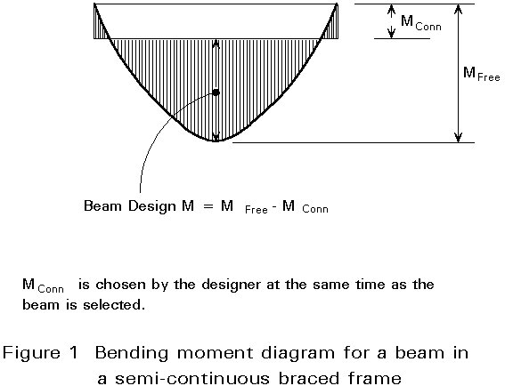
The semi-continuous approach offers a middle course. It is based on designer choice of a convenient beam end moment, as illustrated in Figure 1. This end moment is usually set equal to the resistance of a suitable not-too-elaborate connection detail. The beam is then sized for midspan M = M FREE - M CONN. The connection is, therefore, the key to semi-continuous frame design.
Figure 2 demonstrates the definition of moment connections by strength, rigidity and ductility.
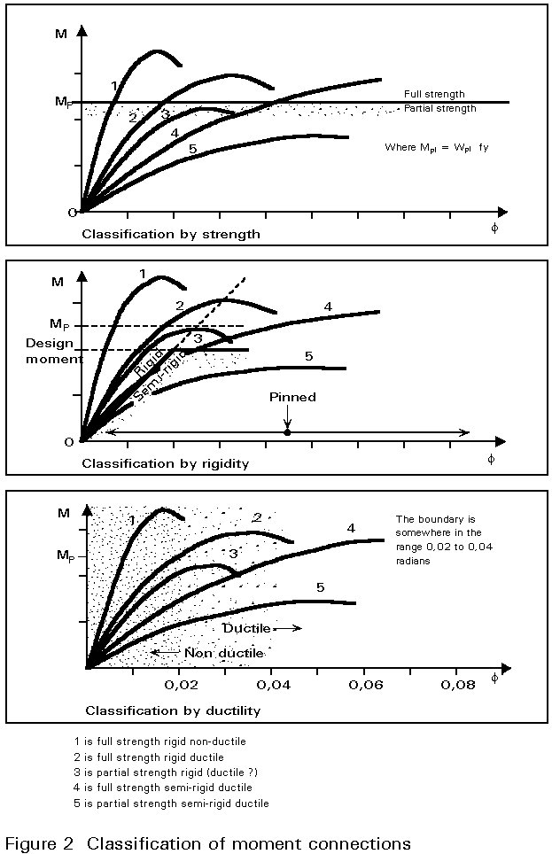
The important features of a connection in semi-continuous framing are that it is ductile and partial strength.
Ductile: capable of acting as a plastic hinge.
Ductility of a connection is synonymous with rotation capacity (the term used in Eurocode 3), and should not be confused with ductility of a material such as steel.
Partial Strength: Able to resist less than the plastic moment of the beam.
Since, in continuous frames, maximum moments occur at the beam ends, it is virtually inevitable that a partial strength connection in this location will be 'overloaded'. It must be capable of rotating plastically to the extent necessary for compatibility with beam end (and possibly column) rotations under design load. The beam may not remain elastic. Around midspan, there is liable to be an almost fully developed plastic hinge. The rotation which the connection must accommodate therefore varies with the circumstances but may be as much as 0,02 to 0,04 radians.
In practice, the chosen moment resistance of the connection is often in the range 30% to 50% of the plastic moment resistance of the beam.
Design of semi-continuous frames, as outlined above, is based on plastic global analysis.
In principle, semi-continuous elastic analysis could also be performed. This implies that rotational springs of appropriate stiffness (rigidity) are used to model the connections.
Elastic global analysis is a relatively unattractive proposition to the designer of a semi-continuous frame. Reliable prediction of rotational stiffness is difficult, and the bending moment distribution depends on this. The interaction between element and connection stiffness and the distribution of moments in the frame makes it very difficult for the designer to control the design and achieve overall economy.
The main reason for mentioning elastic analysis is to introduce the term:-
Semi-rigid: too flexible to qualify as Rigid, but not a pin.
A Rigid connection is stiff enough for the assumptions made in conventional elastic analysis to be valid. The perfectly rigid connection does not exist, but practical connections can approach this ideal sufficiently closely for their flexibility to be neglected in the analysis. In other words the bending moment distribution remains acceptably close to the theoretical one which results from elastic analysis. Codes vary in their definition of where to 'draw the line' for this purpose. The distinction is only relevant to elastic analysis of hyperstatic frames.
This special meaning of the word 'Rigid' is emphasized, in this lecture, by the use of the capital 'R'.
It is important to understand that a connection can be rigid enough to perform its function in the structure without qualifying as Rigid according to the code definition. Semi-rigid connections can be adequately rigid.
It is necessary to be aware that just as the term rigid is sometimes used loosely to mean nothing more than 'rotation-resistant', the term semi-rigid is sometimes used to describe semi-continuous construction in general. This is unfortunate. Although the connections which are the subject of this lecture will often be semi-rigid, what matters is that they are Partial Strength and Ductile.
The neutral term 'Partial Restraint', meaning 'Partial Strength and/or Semi-rigid', will also be encountered.
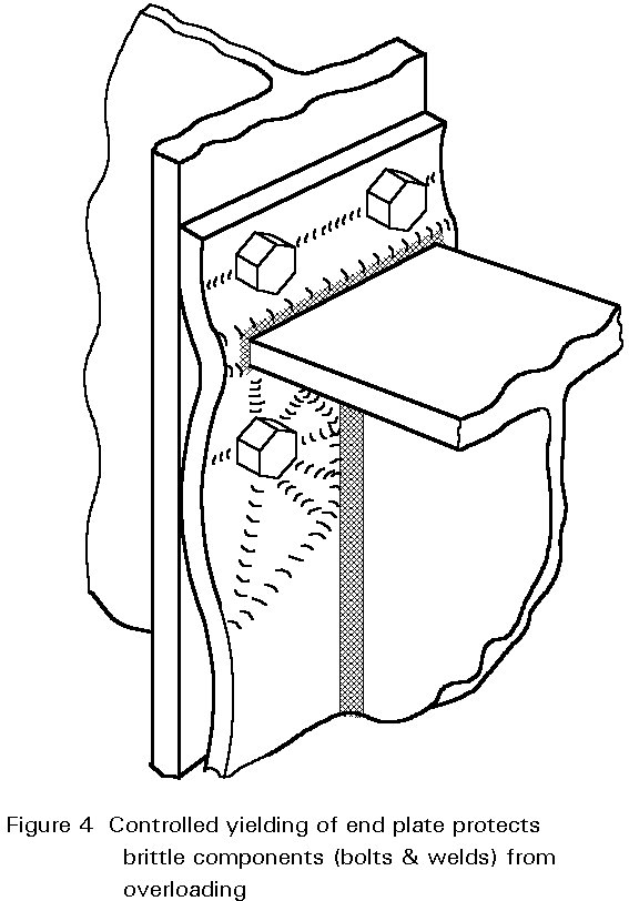
In order to deliver the necessary rotation capacity, some component of the connection must yield in a controlled way. Plates in bending and column webs in shear are suitable candidates.
Most importantly, other parts of the connection must be prevented from failing, because they would do so abruptly. Welds, and bolts in tension, are in this category.
For this reason all-welded connections, apart from some unconventional ones, are not generally compatible with the semi-continuous approach.
To protect the brittle components, e.g. welds and bolts in tension, it is necessary for at least one other component of the connection to be designed as a deliberate 'weak link'. Unusually in structural design, the maximum strength as well as the minimum strength of this component must be limited.
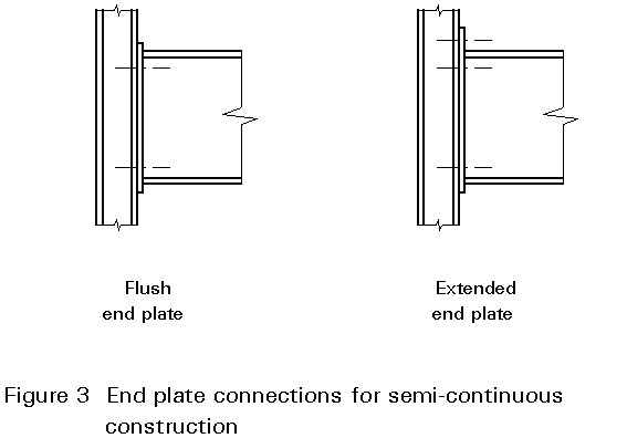
A frequently chosen connection is the bolted end plate, either 'flush' or 'extended', see Figure 3. Other styles of connection may be suitable, but this one is unique in that it is supported by authoritative design rules in Eurocode 3 Annex J [1].
Not all end plate connections are ductile. Figures 4 and 5 demonstrate the behaviour that is required. Generally only Mode 1 behaviour achieves the required ductility.
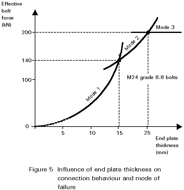
It is usually found necessary to restrict the end plate thickness to approximately 60% of the bolt diameter (assuming bolts not weaker than 8.8). Thicker end plates would transmit more moment but with the risk of premature failure due to the bolts snapping before the required degree of rotation has taken place.
End plate connections designed with regard for strength alone usually have end plates whose thickness equals or exceeds the bolt diameter. They are non-ductile. For example, as shown in Figure 5, a 25 mm thick end plate is necessary to develop the full strength of M24 8.8 bolts.
However, in all respects other than thickness, the ductile end plate can look identical to full strength end plates.
Apart from the inevitable relative inefficiency in bolt utilisation, it should be recognised that the thinner end plate makes the ductile connection less rigid than its orthodox counterpart.
Rigidity, used here as a synonym for rotational stiffness, is significantly more important in unbraced frames than in braced ones. In the former, it contributes to frame stability and sway resistance. In braced frames, its contribution is less crucial; it helps limit beam deflection and restrains column rotation.
The rigidity required to maintain stability and/or serviceability of an unbraced frame varies according to the circumstances - a multibay low rise frame obviously requires less than a slender one, other things remaining equal. However, it is generally less, maybe much less, than that required (according to code rules) for the connection to be designated 'Rigid' for the purpose of elastic analysis.
It is hard to imagine circumstances in which too much rigidity would be an embarrassment, irrespective of whether the frame is braced. Standard details can, therefore, be designed to maximise it. For this purpose, 'compact' bolt arrangements, in which the bolts are placed as close to the flange and web as is practical, are preferable.
In relation to choice of end plate thickness, rigidity and ductility are in direct opposition.
Stiffness of the end plate, which tends to be the most flexible component of the connection and, therefore, dominant, is proportional to its thickness to the power of two if not three. Ductility must not be compromised, so larger and/or stronger bolts, which permit a thicker end plate, are advantageous.
The combination of 15mm thick end plates with M24 bolts (8.8 or 10.9) is often found suitable.
Recalling that the connections in semi-continuous design are the subject of designer choice, it can be seen that a standardized approach holds a special attraction.
It is frustrating for the designer to select a particular trial connection moment, say 30% of the free moment, only to discover after pages of calculation that a connection using two tensile bolts just fails to achieve it.
A relatively small range of standard details, based on preferred geometries, can be presented with tabulated moment resistances for each beam size. This shortcuts the process of trial and error choice of beam size and connection style, and retains much of the simplicity of traditional 'simple' design. Figure 6 shows an example of standard details from the United Kingdom [2] for ductile partial strength connections.
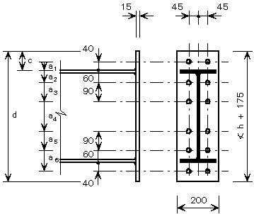
Figure 6. Example of a standard detail
MOMENT RESISTANCE
M.R. (in Nm) = 193 x [h - 0,5 tf + 40]
+ 315 x [h - 0,5 tf - 60]
+ 287 x [h - 0,5 tf - 150]
|
Dimensions for detailing (mm) |
Serial size/Mass per metre |
Moment Resistance (kNm) |
|||||||||
|
Relative to top of steel |
d |
tf |
h |
||||||||
|
a1 |
a2 |
a3 |
a4 |
a5 |
a6 |
c |
|||||
|
40 40 40 40 40 |
60 60 60 60 60 |
150 150 150 150 150 |
395 390 387 383 378 |
485 480 477 473 468 |
585 580 577 573 568 |
88 90 92 93 96 |
720 |
21,3 18,8 17,4 15,6 13,2 |
544,6 539,5 536,7 533,1 528,3 |
533 x 210 122 ¥ 109 ¥ 101 92 82 |
371 368 366 364 361 |
|
40 40 40 40 40 |
60 60 60 60 60 |
150 150 150 150 150 |
317 314 310 307 304 |
407 404 400 397 394 |
507 504 500 497 494 |
91 93 95 96 98 |
650 |
19,6 17,7 16,0 14,5 12,7 |
467,4 463,6 460,2 457,2 453,6 |
457 x 191 98 ¥ 89 Ë 82 74 67 |
310 308 306 304 302 |
|
40 40 40 40 40 |
60 60 60 60 60 |
150 150 150 150 150 |
315 311 307 305 300 |
405 401 397 395 390 |
505 501 497 495 490 |
92 94 96 98 100 |
650 |
18,9 17,0 15,0 13,3 10,9 |
465,1 461,3 457,2 454,7 449,8 |
457 x 152 82 ¥ 74 67 60 52 |
308 306 304 302 299 |
|
40 40 40 40 |
60 60 60 60 |
150 150 150 150 |
263 259 256 253 |
353 349 346 343 |
453 449 446 443 |
89 90 92 94 |
590 |
16,0 14,3 12,8 10,9 |
412,8 409,4 406,4 402,6 |
406 x 178 74 67 60 54 |
268 266 264 262 |
|
40 40 |
60 60 |
150 150 |
252 247 |
342 337 |
442 437 |
89 91 |
580 |
11,2 8,6 |
402,3 397,3 |
406 x 140 46 39 |
261 258 |
¥ - Where ‘tf’ > 18 use EFPTBW to flange
Ë - If beam is S275 use EFPTBW to flange
COLUMN LIMITATIONS
S Fb £ 809 kN
|
S275 |
Grade |
S355 |
||||||||||||||||||||||||
|
v |
iv |
iii |
ii |
i |
Zone |
i |
ii |
iii |
iv |
v |
||||||||||||||||
|
Web Tension |
Web Crushing |
Web Buckling |
Web Shear |
Flange Bending |
Serial size/ Mass per metre |
Flange Bending |
Web Shear |
Web Buckling |
Web Crushing |
Web Tension |
||||||||||||||||
|
_ _ _ _ |
_ _ _ n |
_ _ _ n |
1089 940 814 691* |
_ _ _ _ |
356´368 202 177 153 129 |
_ _ _ _ |
1406 1213 1051 892 |
_ _ _ _ |
_ _ _ _ |
_ _ _ _ |
||||||||||||||||
|
_ _ _ _ _ _ _ |
_ _ _ _ _ n n |
_ _ _ _ _ _ n |
_ 1364 1124 905 791 681* 565* |
_ _ _ _ _ _ n |
305´305 283 240 198 158 137 118 97 |
_ _ _ _ _ _ n |
_ _ 1451 1168 1021 879 730* |
_ _ _ _ _ _ n |
_ _ _ _ _ _ n |
_ _ _ _ _ _ _ |
||||||||||||||||
|
_ _ _ _ _ |
_ _ n n n |
_ _ _ n n |
935 746* 613* 497* 406* |
_ _ _ n n |
254´254 167 132 107 89 73 |
_ _ _ _ n |
1207 963 791* 642* 525* |
_ _ _ n n |
_ _ _ n n |
_ _ _ _ _ |
||||||||||||||||
|
_ _ _ _ n |
n n n n n |
n n n n n |
497* 395* 349* 300* 273* |
n n n n n |
203´203 86 71 60 52 46 |
_ n n n n |
642* 510* 451* 387* 353* |
_ n n n n |
_ n n n n |
_ _ _ _ _ |
||||||||||||||||
|
* Less than S Fb n Reinforcement required |
||||||||||||||||||||||||||
|
SHEAR RESISTANCE See Note 4 |
|
1020 kN |
The strength (moment resistance) of the connection is calculated exactly as for any other end plate moment connection, see Lecture 11.1.2.
The same is true of the rigidity (rotational stiffness) for which Eurocode 3, Annex J gives a formula [1].
The reliability of the predictions of rotational stiffness which are not based on tests is, however, limited. While serviceability calculations may reasonably be based on predictions, the present state of the art is not such as to encourage their use to determine the design ('ultimate') bending moment distribution.
Verification of connection ductility (rotation capacity) is outlined in the next section. It should be understood that in practice these checks are normally made using purpose-designed software or by reference to tables of standard details.
Verification of Ductility
As shown in Figure 7, Eurocode 3, Annex J prescribes that a connection may be regarded as ductile, i.e. it will possess sufficient rotation capacity to act as a plastic hinge, where subject to one of the following conditions:-
(i) Shear zone of the column limits the moment resistance
(ii) Column flange (in bending) limits the moment resistance with Mode 1 failure
(iii) End plate (in bending) limits the moment resistance with Mode 1 failure
Mode 1 failure is the 'double bending' mode which governs if the plate is relatively thin.
Only in the special case of one-sided connections, e.g. perimeter columns, is it realistic to design on the basis of option (i). Where there is a beam on each side of the column, the moments can oppose one another, reducing the shear in the web panel - perhaps to zero.
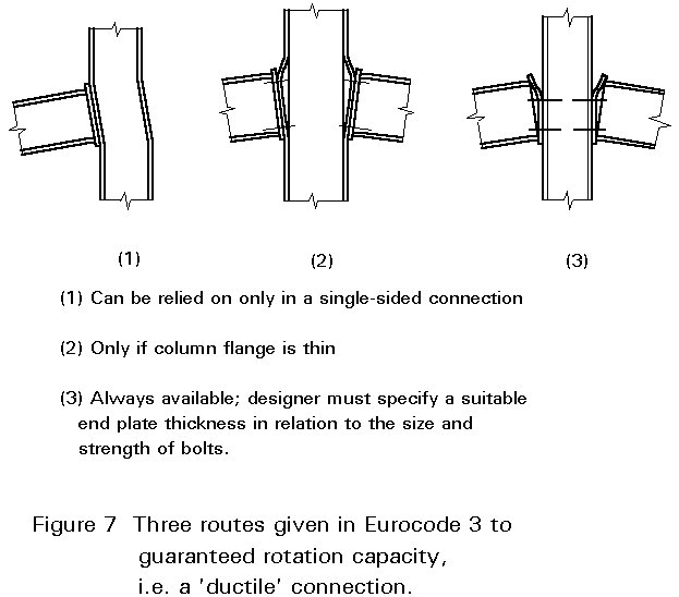
Generally, the column is already sized; any scope that the connection designer has to alter it is in the upwards direction only. Frequently, therefore, (ii) will not be an available option either.
Option (iii), designing for Mode 1 failure in the end plate, is the only universally available route to satisfying the requirement; standard details can be based on this.
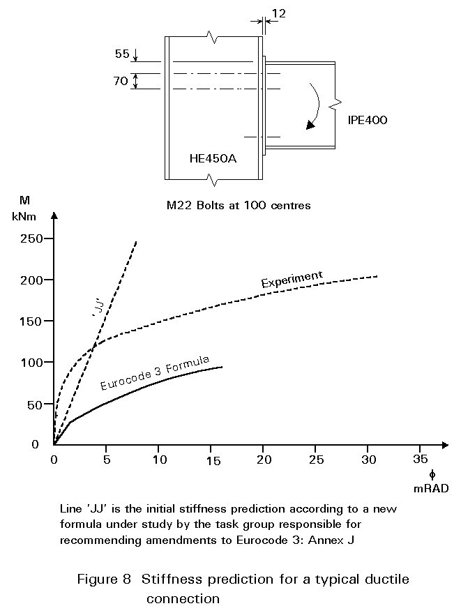
As illustrated in Figure 8, it should be noted that Eurocode 3 Annex J offers a formula by which rotation capacity may be calculated and compared with the designer's assessment of what the situation requires. This formula is applicable to connections in which Mode 2 prevails, i.e. the end plate is somewhat thicker than the limit for Mode1. In practice, it is rather unproductive of rotation capacity, except for the shallowest of beams. In any case, the designer generally prefers to avoid quantifying the required rotation capacity. Satisfying condition (i), (ii) or (iii) above means that the connection is 'ductile' - its rotation capacity will be ample for all normal circumstances.
It is fundamental to the ethos of the semi-continuous approach that, where it is in competition with 'simple' framing, the connections are little, if any, more costly than their 'nominally pinned' counterparts, see Figure 9.
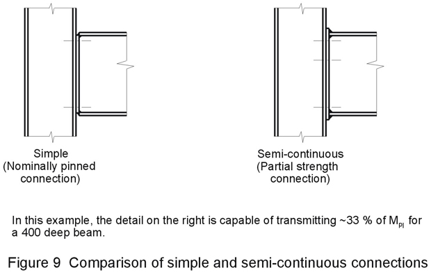
A larger end plate, a slightly larger weld or an extra pair of bolts can be accepted.
However, if stiffeners become necessary in the column, or a haunch in the beam, it is likely that the point has been missed. A saving in the beam size is unlikely to be substantial enough to compensate for these labour-intensive additions. Indeed, it is almost always preferable to increase the weight of a column rather than to weld in stiffeners.
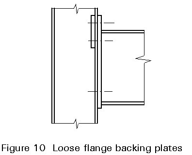
One form of column reinforcement, loose flange backing plates, Figure 10 can, however, be justified as a means of upgrading the resistance of a thin-flanged column at modest cost.
The message is that the designer should exercise his/her freedom to choose the connection moment with due regard for the cost effects of this decision.
Unbraced frames designed according to the wind-moment method which is traditional in some countries, i.e. connections proportioned to resist wind moment only) are, whether their designers recognised it or not, precursors of the semi-continuous unbraced frame. The satisfactory service performance of numerous structures of this type, not all of whose connections would be judged ductile according to the application rules of Eurocode 3, encourages confidence in the acceptability of semi-continuous unbraced frames.
Nevertheless, unbraced frames with ductile partial strength connections should be approached with some caution. It is necessary to ensure that connection rigidity is not unacceptably low for serviceability or stability of the frame.
Ideally, the connection stiffness is predicted and the frame is analysed with the connections modelled as rotational springs. (Formulae are available to modify beam bending stiffness so that this can be performed with programs which do not offer rotational spring elements). This analysis gives sway predictions which can be compared directly with code limits, provided second order effects are negligible, i.e. the frame is non-sway. If they are not negligible, second order analysis is required.
This approach demands knowledge of the rotational stiffness of the connections, which may not be reliably available. It amounts to semi-continuous elastic global analysis.
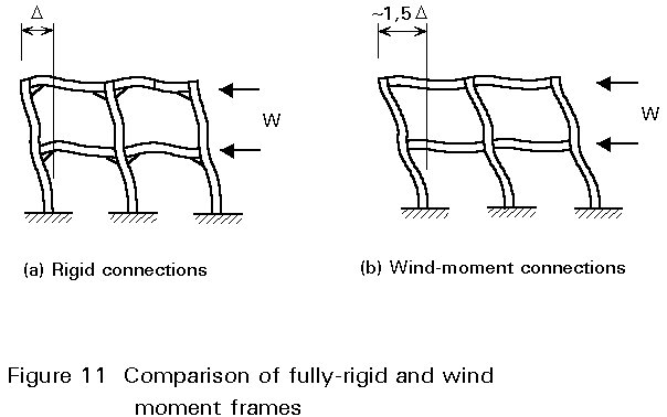
Provided that the structure is low rise and of reasonably normal proportions, a simpler approach can be followed, Figure 11. Parametric studies [3] have shown that it is acceptably accurate to apply an arbitrary multiplier of 1,5 to the sway predicted by a conventional continuous elastic global analysis, subject to certain conditions.
These points are covered in earlier Lectures. They are repeated here as a reminder that rigidity could influence connection design in certain cases, leading perhaps to extended or stiffened end plates where (for strength alone) less elaborate configurations would suffice.
In the case of an unbraced frame, the objective is to avoid bracing rather than to make savings in the beams. The economic comparison is with the full strength and/or rigid connections of the competing 'continuous' design.
The emphasis on avoiding costly welded stiffeners and other labour-intensive fabrication remains valid.
[1] Eurocode 3: "Design of Steel Structures: Part 1.1: General Rules and Rules for Buildings", ENV 1993-1-1, 1992.
[2] Hughes, A. F. et al, "Ductile Connections for Wind-Moment Frames" Steel Construction Institute, Ascot, UK (to be published).
[3] Anderson, D. A. et al, "Wind-Moment Design for Unbraced Frames, Steel Construction Institute, Publication P082, Ascot, UK, 1991.