ESDEP WG 14
STRUCTURAL SYSTEMS: BUILDINGS
To present and illustrate procedures for the design of multi-storey buildings relating to the behaviour of beams, columns and connections. Special attention is paid to the influence of the design of partial-strength connections on the frame behaviour.
Lectures of Group 6: Applied Stability
Lectures of Group 11: Connections: Static Loading
Lecture 11.7: Partial Strength Connections for Semi-Continuous Framing
The influence of partial strength and semi-rigid connections in the design of building frames of structural steel is considered. Plastically designed connections in elastically designed frames and elastically designed connections in plastically designed frames are discussed. The background to relevant parts of EC3 is also presented.
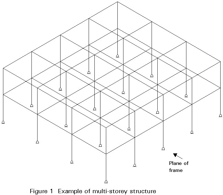
Steel structures for multi-storey buildings consist mainly of columns and beams. A multi-storey structure is shown in Figure 1. Within the structure two directions can be distinguished: a direction in which beams and columns are arranged into frames, and a direction in which the frames are connected to floors or beams in order to form a three-dimensional structure.
It is common practice to ensure the stability of the frames out-of-the-plane by triangulation or by shear walls, cores and the like. The frames are in general connected to the bracing structure with pinned connections. In the plane, the frame can be stabilized by a bracing system, or can be stable in itself (unbraced frame).
The mechanical behaviour of a connection is represented in Line I of Figure 2. The figure shows a moment rotation diagram of a T-connection in a frame (beam-column connection). The real connection behaviour can be represented by a bi- or tri-linear diagram in which a number of properties can be distinguished.
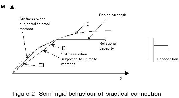
A connection can have a lower design strength than the beam or column which it connects. In that case, a connection is partial-strength. If the stiffness of the connection has a significant influence on the stability and deformations of a frame, the connection should be regarded as semi-rigid or even nominally pinned.
The influence of the connections on the frame behaviour is treated separately for partial-strength connections and semi-rigid connections.
Braced frames are in general designed based on strength conditions and unbraced frames are in general designed based on stability and deformation conditions. Therefore, partial strength connections are mainly used in braced frames, and semi-rigid connections in unbraced frames.
In Eurocode 3, criteria are given for nominally pinned, semi-rigid and rigid beam-to-column connections, when the distribution of forces and moments in the structure is determined using elastic or plastic theory. The structural properties of beam-to-column connections, such as stiffness, resistance and rotation capacity, should be in accordance with the assumptions made in the design of the structure. The structural properties of a beam-to-column connection were indicated qualitatively in Section 1 above.
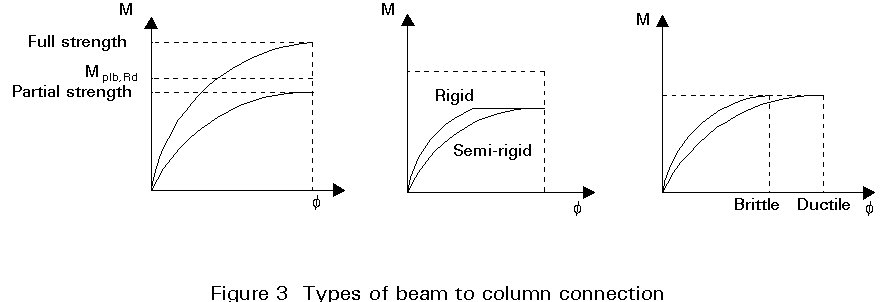
The classification of beam-to-column connections provides the designer with a quick answer to the question how a certain beam-to-column connection, given its the properties in a moment rotation diagram, will behave in the structure. This behaviour can be rigid or semi-rigid with respect to stiffness, full-strength or partial-strength with respect to moment resistance and ductile or brittle with respect to rotation capacity. These properties are illustrated in Figure 3. In this figure Mplb.Rd represents the design plastic moment of the beam. The boundaries between the areas of behaviour of beam-to-column connections are discussed below.
The distribution of forces and moments in a structure is influenced by the flexibility of the connections in that structure. Stability, deformations, and displacements are also similarly influenced.
The flexibility of beam-to-column connections may be neglected in some cases, i.e. the connection may be assumed to be rigid in some cases and a hinge in others. The assumption which can be made depends on the stiffness ratio between the beam-to-column connection and the connected beams and columns.
The structural behaviour will be analyzed by showing the relationship between the parameters
![]() and r. The parameter is the relative rotation stiffness
and r. The parameter is the relative rotation stiffness
![]() =
=![]() , in which s is the rotation stiffness of the beam-to-column connection and
, in which s is the rotation stiffness of the beam-to-column connection and ![]() is the flexural stiffness of the beam. The parameter
r is the ratio between the flexural stiffness of the beam and the column, i.e.
is the flexural stiffness of the beam. The parameter
r is the ratio between the flexural stiffness of the beam and the column, i.e. ![]() ,
in which
,
in which ![]() is the flexural stiffness of the beam and
is the flexural stiffness of the beam and ![]() is the flexural stiffness of the column.
is the flexural stiffness of the column.
For one-bay single-storey frames, both braced and unbraced, the relationships between
![]() and r can be determined as shown in Figure 4.
and r can be determined as shown in Figure 4.
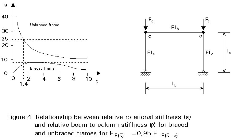
The relationship can be determined at a constant ratio between the Euler buckling load of the frame with semi-rigid connections and the Euler buckling load of the same frame but now with rigid connections. For this ratio, and according to Eurocode 3, the value 0.95 is chosen.
In Figure 4 the relationship between
![]() and r is shown for the unbraced as well as for the braced frame. The mathematical background of these relationships is given in the background report to this subject of Eurocode 3 (9).
and r is shown for the unbraced as well as for the braced frame. The mathematical background of these relationships is given in the background report to this subject of Eurocode 3 (9).
With the aid of the Merchant-Rankine formula (Lecture 7.7) for the unbraced frame, the influence of reduction of 5% in the Euler buckling load on the carrying resistance of the frame can be shown. The reduction is a consequence of the semi-rigidity of the beam-to-column connections.
Suppose Fpl is the load at plastic failure of the frame and FE(![]() = ¥)
is the Euler buckling load of the frame with perfectly rigid connections. Then FE(
= ¥)
is the Euler buckling load of the frame with perfectly rigid connections. Then FE(![]() ) = 0.95 FE (
) = 0.95 FE (![]() = ¥) is the Euler bucking load of the frame with semi-rigid connections which have flexibility such that the Euler buckling load is lower by 5% compared to the situation with perfectly rigid connections.
= ¥) is the Euler bucking load of the frame with semi-rigid connections which have flexibility such that the Euler buckling load is lower by 5% compared to the situation with perfectly rigid connections.
Suppose that FE (![]() =
¥) = k . Fpl.
=
¥) = k . Fpl.
Using connections with a semi-rigidity such that the Euler buckling load reduces by 5%, the following holds:
FE (![]() ) = 0.95 . k . Fpl.
) = 0.95 . k . Fpl.
On the basis of the Merchant-Rankine formula for the determination of the carrying resistance of the unbraced frame,  , it can be shown that the carrying resistance will drop by not more than 5%.
Figure 4 gives the relationship between the geometry of the frame and the ratio of flexural stiffnesses between the connection and the beam for those rotation stiffnesses of the connection which can be assumed to be perfectly rigid, because the flexibility of the connection causes a drop of the carrying resistance of the frame of not more than 5%.
To verify the design of the frame against the requirements, all the geometrical data are required. These data are the sections used as columns and beams together with the lay-out of the beam-to-column connections. From the lay-out of the connections the moment-rotation relationship can be determined on the basis of Annex J of Eurocode 3. With that data the parameters
![]() and r can be determined and, via Figure 4, the influence the connection stiffness has on the distribution of forces and moments, and on the stability of the frame can be shown.
and r can be determined and, via Figure 4, the influence the connection stiffness has on the distribution of forces and moments, and on the stability of the frame can be shown.
The design may have to be made when not all the data are known and it is difficult to estimate before hand what influence the connections will have on the behaviour of the frame. In Eurocode a further simplification is given for this case to enable the connection influence to be estimated.
By choosing a constant boundary value for the factor
![]() , it becomes independent of the parameter r . For braced frames the boundary value is
, it becomes independent of the parameter r . For braced frames the boundary value is
![]() = 8, and for unbraced frames the boundary value is
= 8, and for unbraced frames the boundary value is
![]() = 25.
= 25.
The lines of ![]() = 8 and
= 8 and
![]() = 25 are drawn in Figure 4. It can be seen that the boundary value
= 25 are drawn in Figure 4. It can be seen that the boundary value
![]() = 8 covers the r
-
= 8 covers the r
-![]() relationship for braced frames completely. The boundary value
relationship for braced frames completely. The boundary value
![]() = 25 for unbraced frames covers the
r
-
= 25 for unbraced frames covers the
r
-![]() relationship only if r ³ 1.4. For r < 1.4 the boundary value
relationship only if r ³ 1.4. For r < 1.4 the boundary value
![]() = 25 is, in principle, unsafe. This situation will now be investigated.
= 25 is, in principle, unsafe. This situation will now be investigated.
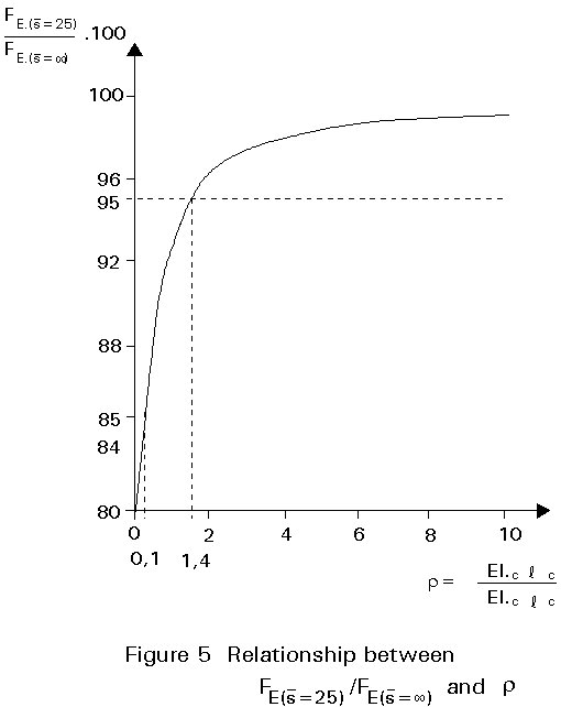
Frames for which r < 0.1 are not realistic, so the value r = 0.1 can be used as a boundary.
Figure 5 shows the relationship between r and (FE (![]() = 25)/FE (
= 25)/FE (![]() =
¥)) . 100%. When r = 0.1 the Euler bucking load based on
=
¥)) . 100%. When r = 0.1 the Euler bucking load based on
![]() = 25 would be not more than 85% of the Euler buckling load if the value for
= 25 would be not more than 85% of the Euler buckling load if the value for
![]() = ¥.
= ¥.
The carrying resistance of the frame based on the Merchant-Rankine formula has reduced as follows:
![]()
where Fcr (![]() = ¥) is the carrying resistance of the frame:
= ¥) is the carrying resistance of the frame:
![]()
![]()
![]() (2)
(2)
The following relationship holds:
![]()
![]()
![]() (3)
(3)
The reduction of the carrying resistance is:
![]()
 (4)
(4)
Even for a relatively slender frame, namely FE (
![]() = 25) = Fpl, so X = 1 the reduction D = 8% and for X = 2 the reduction D = 5.6%.
= 25) = Fpl, so X = 1 the reduction D = 8% and for X = 2 the reduction D = 5.6%.
It can be concluded that ![]() = 25 is a sufficiently safe boundary value for the rotation stiffness of beam-to-column connections in unbraced frames in order to consider them as rigid, ensuring that FE/Fpl ³ 1.
= 25 is a sufficiently safe boundary value for the rotation stiffness of beam-to-column connections in unbraced frames in order to consider them as rigid, ensuring that FE/Fpl ³ 1.
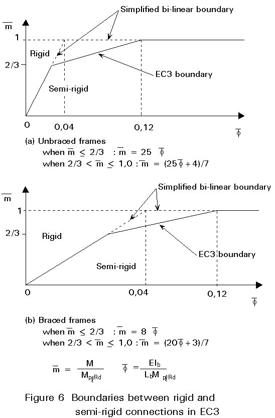
As far as the moment resistance of beam-to-column connections is concerned, classification is simpler. If the moment resistance of the beam-to-column connection is equal to the plastic resistance of the connected beam, the connection is considered as full-strength. If not, the connection is considered as partial-strength. On the basis of the boundary for the rotation stiffness and the boundary for the moment resistance a bi-linear moment-rotation characteristic is achieved, as shown by the dotted lines in Figure 6.
If the moment-rotation characteristic of a beam-to-column connection lies on the left hand side and above the boundary lines, this connection can be classified as rigid and full-strength.
The bi-linear boundary is rather severe for classifying beam-to-column connections, when it is compared with the moment-rotation characteristic of a beam section. If the moment acting on a beam section exceeds the elastic moment resistance, Me = 0.85 Mpl for an I-section, then plastification will develop and the stiffness will decrease. If residual stresses are taken into account plastification will commence at M = 0.7 Mpl. So it is reasonable to cut off the bi-linear characteristic with a third branch.
Tests show that beam-to-column connections with end-plates have an elastic behaviour up to at least 2/3 of the moment resistance of the connection. On this basis, full-strength connections are required to behave elastically up to at least 2/3 Mpl,beam.
Theoretically the plastic resistance of a beam section is reached at an infinitively large rotation of the plastic hinge. In practice a large percentage of the plastic moment resistance is reached at a relative small rotation.
In Figure 6 the boundaries are shown for braced and unbraced frames as given in Eurocode 3. In Figure 6 both axes of the moment-rotation characteristics are normalised by dividing the moment by the plastic moment resistance of the beam, so
![]() = M/Mpl; beam and by dividing the rotation by a reference rotation, so:
= M/Mpl; beam and by dividing the rotation by a reference rotation, so:
![]() (5)
(5)
If the portion of its moment rotation characteristic which is used lies below the appropriate line in Figure 6, a beam to column connection should be classified as semi-rigid, according to Eurocode 3 (Clause 6.9.6.2), unless it also satisfies the requirements for a nominally pinned connection.
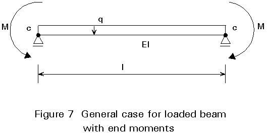
The requirements for rotational capacity are different for unbraced frames and braced frames. For unbraced frames, rotation capacity has to be calculated with help of global frame analyses. The calculation is as follows: Assume a beam has a pinned connection at both ends and is loaded by an equivalent distributed load transverse to the axis as shown in Figure 7. The ends of the beam are loaded with external moments M. The rotation at the end support due to the load will be:
![]() (6)
(6)
In Figure 8 the M-f rotation characteristics of three connections with strengths MRd (I,II and III) are shown.
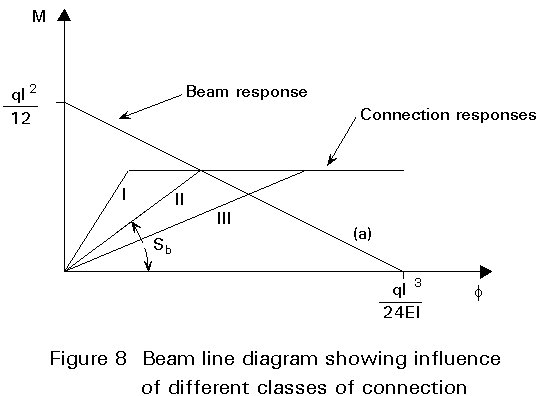
Line II represents a connection with a stiffness which fits the elastic model as shown in Figure 7. No plastification occurs in the beam when reaching the equilibrium situation. The stiffness of this connection is:
 (7)
(7)
Provided that:
![]() (8)
(8)
where Mpl.b is the moment resistance of the beam at mid span, this stiffness can be used in three situations.
For S < Sb (Line III): Plastification will occur in the mid span of the beam and, the required rotational capacity equals ![]() . As a matter of fact, this will always occur in plastically designed connections. It is important to check, whether the beam at mid span has sufficient rotational capacity. In other words: Is the section at mid span an Eurocode 3 Class 1 section (see Lecture 7.8.1(i).
. As a matter of fact, this will always occur in plastically designed connections. It is important to check, whether the beam at mid span has sufficient rotational capacity. In other words: Is the section at mid span an Eurocode 3 Class 1 section (see Lecture 7.8.1(i).
For S = Sb (Line II), no plastic hinges will occur in the structure.
For S > Sb (Line I) plastic hinges will occur in the connections. In that case, the rotational capacity of the connections has to be equal or greater than:
![]() (9)
(9)
This is the rotation at the intersection between the horizontal branch of Line I and Line (a) in Figure 8. If the moment resistance of the connection is determined conservatively, a positive effect is produced in the required rotational capacity of the connection. For very flexible connections (S < Sb), the same effects arises if stiffness is underestimated.
A classification with respect to rotation capacity is not yet possible for unbraced frames. The rotation capacity need not be checked only in cases where the moment resistance of the beam-to-column connection is larger than 1.2 Mpl;beam. The plastic hinge will always form on the beam section adjacent to the connection. In other cases the rotation capacity should be checked if redistribution of moments is taken into account. For unbraced frames the required rotation capacity has to be calculated and checked against the rotation capacity which is available in the connection. For braced frames the required rotation capacity can be determined by looking at the beam mechanisms which will form.
It appears that the classification described above can be used safely also for multi-storey frames and multi-bay frames (9).
Table 1 gives a summary of the possible relationships which may be adopted in designing frames and connections. Frames and connections can be designed either by elastic theory or by means of plastic theory. It is even possible to perform the calculations for frames on the basis of elastic theory and for connections on the basis of plastic theory, or the other way around.
There is, however, one limitation. A connection which remains elastic up to failure can only be used in frames designed by plastic theory provided that the calculated moment resistance is higher than that of the connected beam, and the beam sections have to be of the Class 1 type (see Lecture 7.8.1(i)). Therefore, a full-strength connection is required in order to achieve sufficient plastic deformation adjacent to the connection.
The summary given in Table 1 only holds for partial-strength connections. When the force distribution in a connection is based on elastic theory, the connection will in general be stiffer than a connection designed in accordance with plastic theory. Clearly, this statement only holds when the connection in reality fulfils the assumptions used in the elastic or plastic theory calculations. It can be illustrated as follows. In using elastic theory, the hypothesis of Bernoulli holds (cross-sections remain plane). Such a hypothesis is employed to calculate the force distribution in the bolts connecting the end plate to the column flange. In reality, the end plate and the column flange have to remain plane. If this is realised, the connection is stiff because the only deformation is caused due to the elongation of the bolts.
Using plastic theory, it is necessary for the components in the connection to deform sufficiently in order to obtain a redistribution of forces and the formation of a failure mechanism inside the connection. The consequence is that such a connection is in general less stiff than a connection designed according to elastic theory.
Table 1 shows which relationships between the design methods for frames and connections need further explanation. The behaviour of elastically designed frames with elastically designed fully-rigid connections is well known. Connections calculated on the basis of elastic theory which remain elastic up to failure are not allowed in frames designed by means of plastic theory, unless the moment resistance of the connections is higher than that of the connected beams. On the other hand, connections designed in accordance to plastic theory can always be used in elastically designed frames.
In Table 1, references are given relating to the design of braced frames according to the elastic theory, taking second-order effects into account. These references discuss the use of the stiffness of the connection together with the bending stiffness of the beam in order to reduce the (elastic) effective length of the column. In (10) it is shown that this approach leads to a strength requirement for both the connection and the beam.
In calculating the force distribution in a frame using elastic theory, the ultimate carrying resistance is not calculated. Instead the forces and moments due to the design load are computed. If the ratio n between the Euler buckling load and the design load is small, say smaller than 10, (see Lecture 7.7) second-order effects have to be taken into account. This can be done by multiplying the components of the moments due to side-sway (in the case of unbraced frames) by the amplification factor n/(n-1). If the moments, calculated in this way, are smaller than the ultimate moment resistances of the various connections, then the connections meet the design requirements.
In the connections, designed in accordance with plastic theory, plastic deformations will occur when the ultimate moment resistance is reached. This effect is taken into account in calculating the Euler buckling load using the bi-linear approximation of the connection behaviour, which leads to a safe result (8). In the case of braced frames, the moments in the connections due to loading will perhaps be underestimated if a low rotational stiffness is used. Therefore, one should take an upper bound for the connection stiffness when calculating safe values for the moments in the connections. This approach is in contradiction to the advice given earlier, namely the use of the secant stiffness (bi-linear approximation).
It is shown in the literature that using the bi-linear approximation for the rotational stiffness of the connection in calculating the moments in the connection is still safe provided that the connection possesses sufficient deformation capacity. In the case of unbraced frames the use of a lower bound for the rotational stiffness of the connection will lead to higher values for the moments in the connections due to the increased second-order effects. However, the first-order elastic moment in the connection decreases when a lower rotational stiffness is used. A lower bound for the rotational stiffness of connections in an elastic design of an unbraced frame does not necessarily lead to a safe elastic calculation of the moment in the connection. It is therefore necessary to use connections with sufficient rotational capacity even in an elastically designed frame.
In frames where more than one plastic hinge is necessary in order to reach the plastic failure mechanism, the first, second and subsequent plastic hinges have to rotate until the last plastic hinge is formed. This requirement holds for braced as well as for unbraced frames. Partial-strength connections which remain elastic up to failure are not to be used, because they possess insufficient deformation capacity. A method is given above for the calculation of the required rotational capacity of connections in braced frames. The required rotational capacity in unbraced frames is larger, and should in fact be calculated for the actual geometry of the unbraced frame. In most cases, however, an upper bound for the required rotational capacity is about 0.04 radians.
× design resistance
× stiffness
× rotation capacity
Table 1 Summary of Possible Design Relationships between Frames and Connections
|
Partial-strength connection |
|||||||
|
Elastic Design |
Plastic Design |
||||||
|
Rigid |
Semi-rigid |
Full-strength |
Partial-strength |
||||
|
Frame |
Elastic theory |
First-order |
Braced |
Common practice |
Moment-rotation has to be known |
No particular problems to be expected |
No particular problems to be expected |
|
Unbraced |
See Ref 4 |
Moment-rotation characteristic has to be known |
|||||
|
Second-order effects included |
Braced |
See Ref 4 |
See Refs 6, 7 |
See Ref 4 |
No particular problems to be expected |
||
|
Unbraced |
Moment-rotation characteristic has to be known |
See Ref 5 |
|||||
|
Plastic theory |
First-order |
Braced |
Not allowed |
See Ref 4 |
No particular problems to be expected |
||
|
Unbraced |
Moment-rotation characteristic has to be known |
||||||
|
Second-order effects included |
Braced |
See Ref 4 |
See Refs 1-3 |
||||
|
Unbraced |
Moment-rotation characteristic has to be known |
||||||