ESDEP WG 14
STRUCTURAL SYSTEMS: BUILDINGS
To describe the assumptions of the wind-moment method for the design of unbraced frames. To summarise the justifications of the method. To show the method of analysis and appropriate design rules.
Lecture 6.3: Elastic Instability Modes
Lecture 7.2: Cross-section Classification
Lectures 7.8: Restrained Beams
Lectures 7.10: Beam Columns
Lecture 14.8: Classification of Multi-Storey Frames
Lecture 1B.2.1: Design Philosophies
Lectures 1B.7: Introduction to Design of Multi-Storey Buildings
Lecture 11.7: Partial Strength Connections for Semi-Continuous Framing
Lecture 14.7: Anatomy of Multi-storey Buildings
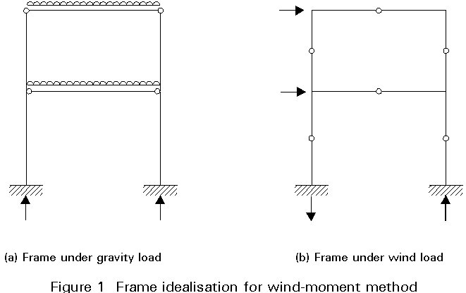
The wind-connection method for unbraced frames renders the structure statically determinate and thereby avoids interaction between global analysis and member design. It assumes that the connections act as pins under gravity load, whilst under horizontal load the connections behave as rigid joints.
Studies on frames designed by the method have given a suitable range of application. The typical behaviour of wind-moment frames is described and those aspects that require particular attention to achieve a satisfactory design are identified. The method of global analysis is explained and appropriate rules for member design are summarised.
In some countries, e.g. UK, Australia and USA, a simplified method for the design of "low-rise frames" has been in use for many years. This is known as the "wind-moment" or "wind-connection" method. It is recognised within relevant national recommendations and the experience achieved in its application throughout these countries has been satisfactory. As a result, it is widely used.
The method is not universally applied though. In the UK its use is now limited to simple frames, regular geometry, with a maximum of 8 floors and 4 spans, maximum heights of 5m between floors, maximum span distances of 12m and maximum relative lengths of 0,5 and 2,0 between spans.
In many other countries, this simplified method is not widely known and is not included in their standards, hence its application is not possible. It is not specifically included in the current version of Eurocode 3 [1]. Despite this, it seemed useful to dedicate one lecture to this method and to develop a practical application example. The method continues to be widely used, at least in those countries mentioned previously, and the lecture is therefore an interesting piece of background information for many lecturers.
Perhaps the inclusion of this Lecture may also widen the long-standing and inconclusive debate regarding the type of simplification and level of rigour that should be adhered to in design methods laid down in structural codes.
Where a steel frame is unbraced, an established design technique is to rely on the rotational stiffness of the connections to provide resistance to wind, even though such restraint is ignored under the action of gravity loads. This approach is termed the 'wind-moment' or 'wind-connection' method.
In its usual form the method assumes:
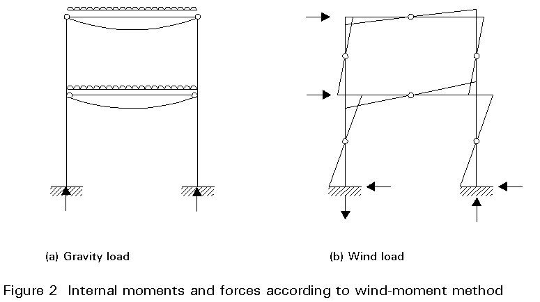
Members and connections are proportioned initially to withstand gravity load. The internal forces and moments due to gravity load and wind (Figures 2a and 2b) are then combined in appropriate load cases. The design for strength is completed by amending the initial section sizes and other details for the members and connections, to withstand the combined effects.
No calculation is made for second-order moments due to the 'P-D' effect. It is assumed that these moments can be accounted for by using effective column lengths greater than the true lengths, for axes about which sway can occur.
For serviceability, sway deflections are calculated assuming connections are rigid.
The advantage of the method is its simplicity. As the frame is rendered statically determinate, internal moments and forces are not dependent on the relative stiffnesses of the members. The need to repeat the analysis to correspond to changed section sizes is thereby avoided. Consequently, the method has been used extensively [2, 3], although it has not been verified as a generally applicable approach.
The justification of the method has been partly in the fact that buildings designed on this basis have proved satisfactory in use. In recent years, the method has been regarded as a form of semi-rigid design and analytical justification has been carried out on this basis [4-7]. The conclusions are as follows:
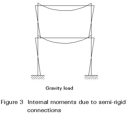
These members tend to be overdesigned for the following reason. Beam design is usually governed by the sagging internal moment due to gravity load. The semi-rigid nature of the connections causes hogging support moments to arise (Figure 3). As the usual form of the method assumes zero support moments (Figure 2a), no advantage is taken of the reduction in sagging moment.
These members tend to be underdesigned, due to the detrimental effect on such members of the hogging moments developed in the beams. These moments particularly affect external columns and other members subject to unbalanced loading. However, as columns are also designed to support axial load, the underdesign of the columns is not as significant as the overdesign of the beams.
The beam-to-column connections will generally be underdesigned. This is because the internal moment for at least one end of a beam will be greater than that predicted by the method, due to the hogging moments due to gravity loads (see above). As beams are usually governed by mid-span moment, whilst connections are sized only for end moment, the connections will generally be only 'partial-strength' with respect to the beams.
These deflections are larger than those predicted assuming rigid joints. This is because of the semi-rigid and partial-strength nature of the connections.
The onset of frame instability will be above the design load level in low and medium-rise frames. For repeated variations of loading expected during the lifetime of the structure, such as reversals of wind load, the frame will 'shake down' with connections then behaving elastically.
Some justification for the method is also given by rigid-plastic theory [8]. According to this theory, the collapse condition has the following characteristics:
× a mechanism of plastic hinges has formed
× the internal moments and forces are in equilibrium with the applied loads
× nowhere does the internal moment exceed the plastic moment of resistance
Provided that the second and third conditions are satisfied, the Lower-Bound Theorem [8] states that the applied loads are either less than or equal to the loads which collapse the frame. These conditions are met by the wind-moment method, which will therefore provide safe designs, provided that the frame also satisfies the assumptions of rigid-plastic theory:
× the effect of deflections on equilibrium can be neglected
× collapse does not occur as a result of any form of buckling
These assumptions therefore indicate those aspects of design that require particular attention if the wind-moment method is to provide frames of adequate strength.
An analytical study has been made of frames designed by the method using a limit states approach [7]. This lecture describes how the method can be used in a manner consistent with Eurocode 3 [1]. The recommendations cover global analysis and member design. From the results of the studies, these recommendations are expected to result in designs for low- and medium-rise frames which possess adequate resistance.
Frame Layout
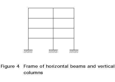
The method applies to steelwork which can be idealised as a series of unbraced plane frames.
The range of application is restricted to multi-storey plane frames in which:
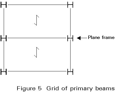
The limitations concerning the number of storeys and bays have been chosen on basis of References [6, 7]. The main reasons for these limitations are:
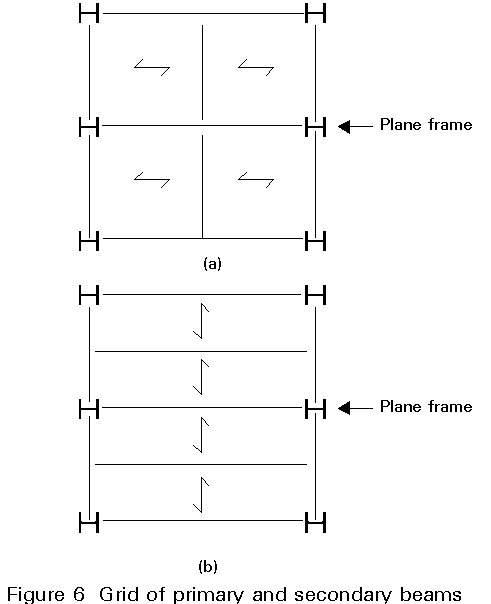
The arrangement of beams in Figure 6b reduces the gravity load carried by the beams forming part of the plane frame. This leads to smaller beam sections in the plane frame, compared to the grids shown in Figures 5 and 6a. All three arrangements have been considered in the study [7] which forms the basis of the recommendations. Grids which do not conform to one of these arrangements are outside the scope. This limitation is required because their possible effect on the stiffness and strength of beams relative to columns has not been studied.
Frame dimensions
Based on the dimensions of the frames studied, the range of application is limited according to the following:
The actual height of a column should be limited because sway stiffness is inversely proportional to the square of the length of the member.
Other limitations are given in Table 1.
The limits are not unduly restrictive in practice.
Structural sections
Sections may be in S235, S275 or S355 steel, or in steel having similar structural properties. The same grade of steel should be used for all sections in a frame. In addition:
The reasons for these limitations are now given.
The method does not provide an exact calculation of column end moments. HE, UC or similar sections with substantial buckling resistance moment should therefore be used for these members.
Column sections should be orientated as recommended because the study [7] did not examine structures in which the beams frame into the column web. There is not yet an accepted method for predicting the behaviour of such connections.
The recommended orientation of the beam sections is usual practice. It is necessary to adhere to this to provide stiffness in the plane of the frame.
Beam-to-column connections
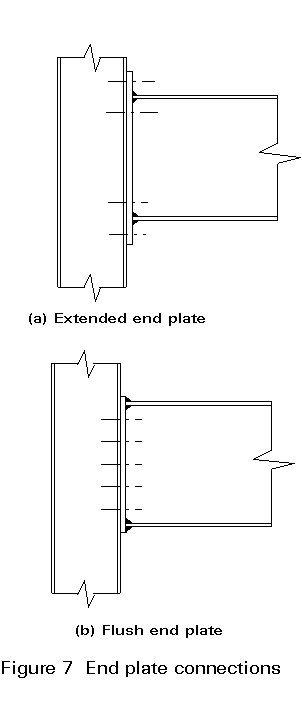
Extended end-plate (Figure 7a) or flush end-plate (Figure 7b) connections should be used. Connections in wind-moment frames form part of the subject matter of Lecture 11.5. It is important to note that since the method results in partial-strength connections which are required to deform plastically, each connection should be designed to have sufficient rotation capacity.
Column bases
Columns should be rigidly connected to foundations by bases designed in accordance with usual practice for this type of construction.
Frames with pinned bases are excluded from the recommendations given here. This is because columns with pinned bases require large effective lengths if they are to be safely designed. Such members also cause large sway deflection in the bottom storey of the structure.
Loading
The range of application is restricted to the following values of loading:
The tendency to underdesign columns and connections, because of neglect of end moments due to gravity load (Figure 3), is increased if the wind load is low. The restrictions on maximum gravity load and minimum wind speed restrict this tendency.
If the wind load is so high that it begins to govern the design of the beams, the frame is best designed as rigid-jointed. This is because the serviceability limit on sway is likely to control the design.
Load combinations
The following load combinations should be used in design:
Frame imperfections should be taken into account by applying equivalent horizontal forces according to the Eurocode 3 rules [1].
Unbalanced ("chequer-board") gravity loading may be critical in the design of internal columns, and should therefore be considered in multi-bay frames.
The load combination 1,35 (Dead load) + 1.50 (Wind load) will usually govern the design of the connections as moment-resisting components.
Internal moments and forces due to gravity load
Under gravity load, allowance should be made for the partial-fixity of the connections between a beam and a column by an end restraint moment equal to 10% of the maximum sagging moment in the beam, assuming the beam to be simply supported. In addition, the shear force at the end of the beam should be assumed to act on the column at a distance of 100 mm from the face of the column. Internal moments in beams though should be calculated for a span equal to the distance between centre-lines of columns.
Each column has to be designed to resist the algebraic sum of the restraint moments from the beams at the same level on each side of the column, in addition to moments due to eccentricity of connections. The net moment applied at any one level should be divided between the column lengths above and below the level in proportion to the stiffness of each length.
The moments applied to the column due to partial-fixity and eccentricity should be assumed to have no effect at the levels above and below the level at which they are applied.
The assumption above of an end moment equal to 10% of the free moment combined with moments due to eccentricity of connections offsets to some extent the tendency of the method to underdesign columns and connections.
Internal moments and forces due to horizontal load.
Horizontal design loads arise due to:
The analysis for internal moments and forces due to horizontal load should be by the "portal method" [2]. The following assumptions are made:
The assumed points of contraflexure for a single bay frame are shown in Figure 1b.
Analysis by "portal method"
Consider the upper part of a single bay frame shown in Figure 8a. The upper part of the diagram in Figure 8b shows the forces on the portion of the frame above the points of contraflexure A and D, whilst the lower part shows the forces on the portion ABCDEF of the frame. In the derivation which follows, compressive axial force is denoted by N.
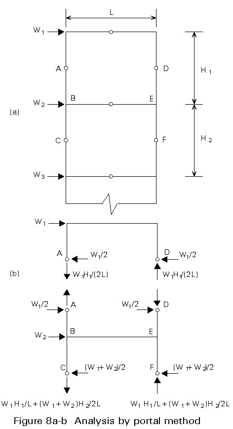
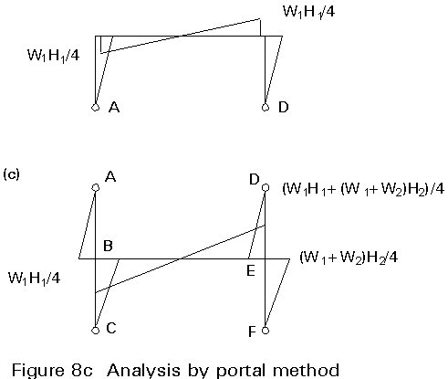
The compressive axial forces at A and D are obtained by taking moments about either D or A and by considering vertical equilibrium. Taking moments about A:
NDL = W1 H1 /2 (1)
Hence:
ND = W1 H1 /(2L) (2)
Since ND + NA = 0 it follows that:
NA = -W1 H1 /(2L) (3)
As these forces are now known, the axial forces at C and F can be calculated by taking moments about either F or C for the region ABCDEF and by vertical equilibrium. Taking moments about C:
(NF - ND) L = W1 (H1 + H2)/2 + W2 H2 /2 (4)
Substituting for ND from Equation (2) and re-arranging:
NF = W1 H1 /L + (W1 + W2 ) H2 /(2L) (5)
By vertical equilibrium, NC + NF = 0 and NC can therefore be found.
The moments in the columns at roof level are clearly given by W1 H1 /4. For equilibrium, these moments are also the moments at each end of the roof beams.
The moment in the upper column at B due to the force at A is also W1 H1 /4, whilst that in the lower column at B due to the force at C is (W1 + W2) H2 /4. The same values apply in the leeward side of the frame. It follows that the moment at each end of the beam BE, which resists the sum of column end moments at B or E, is given by:
MBE = MEB = (W1 H1 + (W1 + W2) H2)/4 (6)
A similar calculation procedure can be followed for other storeys in the frame, or for other bays of a multi-bay structure.
The resulting bending moment diagram for a complete single bay frame is shown in Figure 2b.
As the wind-moment method can be justified in part as a method of plastic design, cross-sections must be able to form plastic hinges and participate in collapse mechanisms. To prevent premature failure by local buckling, sections must therefore be Class 1, Plastic.
The moment resistance though should be restricted to 90% of the plastic moment, to provide restraint to the columns.
Effective lengths
Effective lengths for compression resistance, Pc:
For in-plane behaviour (bending about major axis):
LE = 1,5 L (7)
For out-of-plane behaviour (bending about minor axis):
LE = 1,0 L (8)
These effective lengths are nominal values which, in conjunction with the other recommendations, were found in the studies [7] to result in adequate column sections. The value for out-of-plane behaviour is based in the frame being effectively held against out-of-plane sway.
Equivalent slenderness for buckling resistance moment, Mb:
The slenderness lLT should be calculated assuming that the effective length factors k and kw given in Eurocode 3 [1] are both unity, i.e. no fixity. In addition, the factor C1 needed for the calculation of lLT for a rolled H-section should be taken as unity.
These factors are consistent with simple design. As the end moments are not calculated by exact analysis, the factor C1 should be taken as the most pessimistic value, which corresponds to single curvature bending.
Design moments
Under each combination, the column end moment should be taken as the sum of:
As the horizontal load may reverse, the total moment should be calculated by addition of the numerical magnitudes of the component moments.
Class of section
Sections should be Class 1, Plastic, for the same reason as for the design of beams.
Overall buckling check
The proposed sections should satisfy the checks for combined bending and axial compression given in Eurocode 3, including that in which lateral-torsional buckling is the potential failure mode. The formulae include allowance for the beneficial effects of moment gradient by means of equivalent uniform moment factor, b. As the end moments are not calculated by exact analysis, the factor b should have the most pessimistic value, which corresponds to single curvature bending.
General
The significance of sway deflections in the design of unbraced frames is influenced by the ratio of gravity load to wind load. Even though the design of some frames will be governed by limitation of sway, for others a design made for the ultimate limit state will be adequately stiff.
Design codes give recommended limits on deflections, but these limits are not performance criteria; rather, the limits are intended for comparison with the results of calculations, usually on bare frames. The justification for these limits rests on the satisfactory performance of structures in practice.
Analyses accounting for connection flexibility shows that sway deflections in wind-moment frames are significantly larger than those predicted assuming rigid joints, and yet, as far as is known, structures incorporating such frames do not exhibit distress in practice.
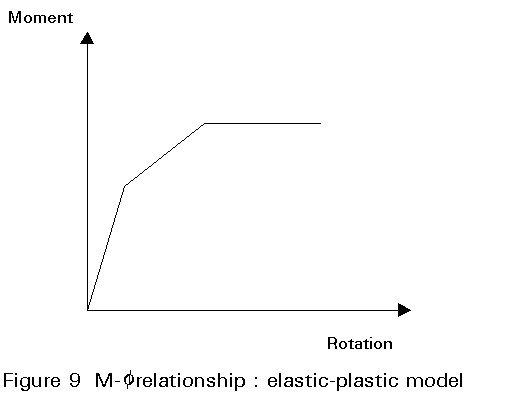
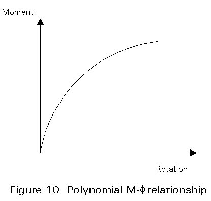
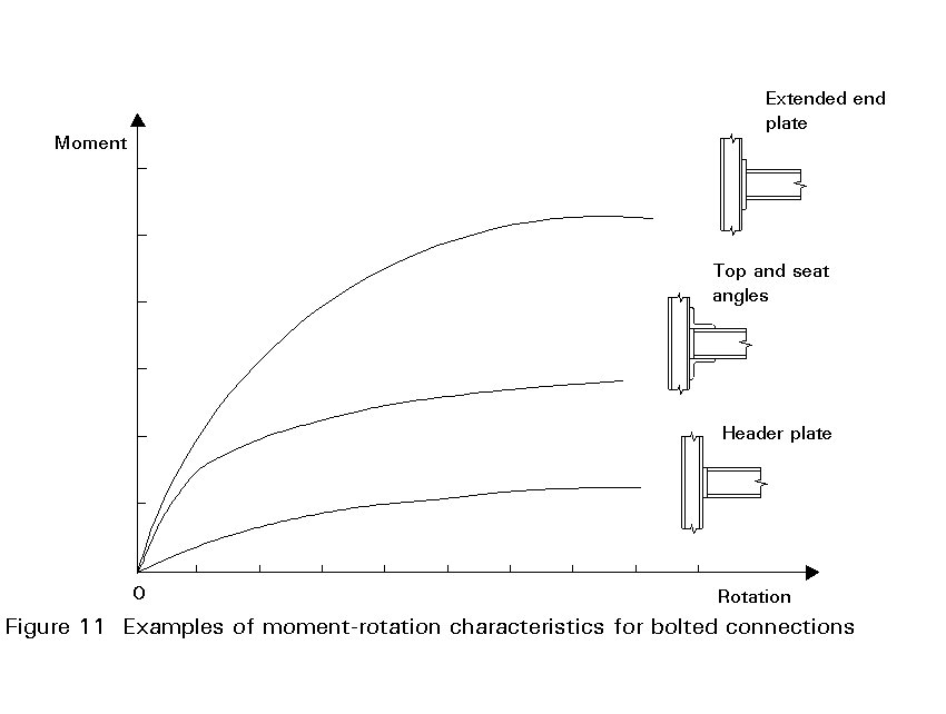
The increase in deflection given by such analyses is dependent on the moment-rotation (M - y) relationship of the connections. The calculated increase in deflection is large if the M - y relationship is represented by an elastic-plastic approximation (Figure 9). A lesser increase is calculated if M - y is represented by a non-linear curve without a plateau (Figure 10). In shape the latter conforms more closely to the experimental behaviour of connections (Figure 11).
Even with an elastic-plastic approximation, studies [7] show that wind-moment frames subject to only light wind load will not deflect more than the Eurocode 3 [1] limit of 1/500th of the total height.
For frames with high wind load, in which deflections are critical, the non-linear representation of connection behaviour gives an increase in deflection of up to 60% [7].
Recommendations
In accordance with usual practice, the design made for the ultimate limit state should be analysed as an elastic rigid-jointed frame to determine sway deflections.
If the deflections are unacceptable, then the design should be revised to provide additional stiffness:
If the rigid-frame deflections are acceptable, the values should be increased by 60%. If the increased values are unacceptable, then the frame should be redesigned, following the recommendations in the previous paragraph. Otherwise, the design of the members is complete.
[1] Eurocode 3: "Design of Steel Structures": ENV 1993-1-1: Part 1.1, General rule and rules for buildings, CEN, 1992.
[2] Construction Steel Research and Development Organisation, Steel Designers' Manual, Crosby Lockwood Staples, 1972.
[3] American Institute of Steel Construction, Manual of Steel Construction, AISC Chicago, 1980.
[4] Nethercot, D. A., "Joint Action and the Design of Steel Frames", The Structural Engineer Vol. 63A, No. 12, December 1985, pp. 371-379.
[5] Gerstle, K. H., "Flexibly Connected Steel Frames, Steel Framed Structures", Stability and Strength (ed R. Narayanan), Elsevier, 1985, pp205-239.
[6] Ackroyd, M., "Design of Flexibly Connected Unbraced Steel Building Frames", Journal of Constructional Steel Research Vol 8, 1987, pp 281-286.
[7] Anderson, D., Reading, S. J., Najafi, A. and Kavianpour, K., "Wind-Moment Design of Unbraced Frames", Steel Construction Today Vol 6, No. 4, July 1992, pp. 159-164.
[8] Neal, B. G., "The Plastic Methods of Structural Analysis", Chapman and Hall, 1977.
Table 1
|
Relative dimensions |
Minimum |
Maximum |
|
Bay width: storey height (bottom storey) |
0,75 |
2,00 |
|
Bay width: storey height (above bottom storey) |
0,90 |
2,50 |
|
Greatest bay width: smallest bay width |
1,00 |
2,00 |
Table 2: Maximum column height
|
Bottom storeys |
6,0 m |
|
Other storeys |
5,0 m |