ESDEP WG 7
ELEMENTS
To introduce the principles of beam-column behaviour and design through the concepts of the interaction of the compressive and bending load components.
Simple bending theory
Lecture 7.2: Cross-Section Classification
Lectures 7.5: Columns
Lectures 7.8: Restrained Beams
Lecture 7.11: Frames
Worked Example 7.10: Beam Columns
This lecture explains the basic concepts of interaction between bending and compression effects by concentrating on uniaxial, in-plane behaviour. This permits topics such as amplification of moments, interaction formulae and the use of compressive resistance and bending resistance to be discussed without the complication of requiring consideration of torsion and out-of-plane response.
Beam-columns are defined as members subject to combined bending and compression. In principle, all members in frame structures are actually beam-columns, with the particular cases of beams (F = 0) and columns (M = 0) simply being the two extremes. Depending upon the exact way in which the applied loading is transferred into the member, the form of support provided and the member's cross-sectional shape, different forms of response will be possible.
The simplest of these involves bending applied about one principal axis only, with the member responding by bending solely in the plane of the applied moment. Only this case will be considered in this lecture; more complex behaviour is covered in Lecture 7.10.2.
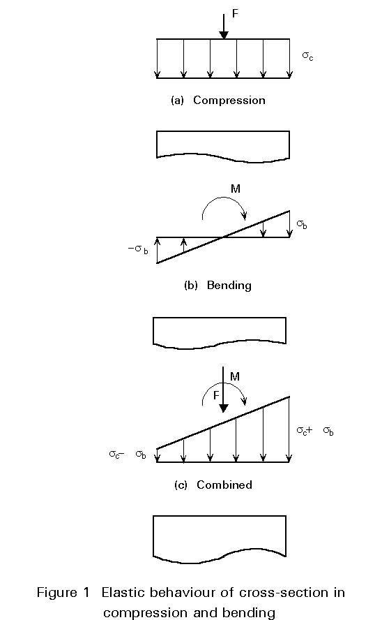
Figure 1 shows a point somewhere along the length of an H-shape column where the applied compression and moment about the y-axis produce the uniform and varying stress distributions shown in Figures 1a and 1b.

For elastic behaviour the principle of superposition may be used to simply add the two stress distributions as shown in Figure 1c. First yield will therefore develop at the edge where the maximum compressive bending stress occurs and will correspond to the condition:
fy = sc + sb (1)
where:
fy is the material yield stress
s
c = N/A is the stress due to the compressive load Ns
b =Alternatively, if full plasticity is allowed to occur, then the failure condition will be as shown in Figure 2 and the combination of axial load and moment giving this condition will be:
|
a. |
For |
yn £ (h-2tf)/2 |
neutral axis in web |
|
|
NM = 2fytwyn |
|
|
|
MN = fybtf (h-tf) + fy |
(2) |
|
|
b. |
For |
yn > (h-2tf)/2 |
neutral axis in flange |
|
|
NM = fy |
|
|
|
|
MN = |
(3) |
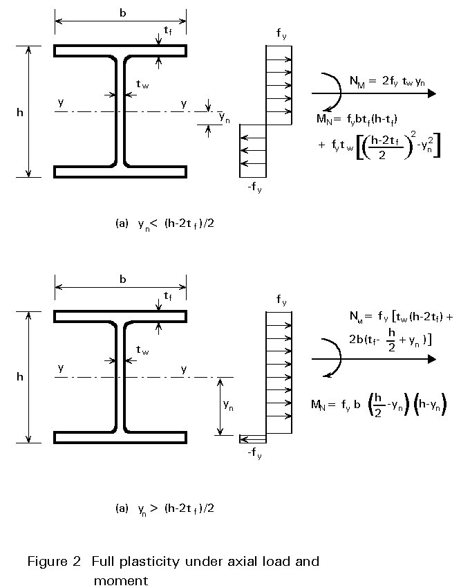
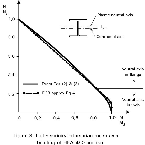
Figure 3 compares Equations (2) and (3) with the approximation used in Eurocode 3 [1] of:
MNy = Mpl.y (1 - n) / (1 - 0,5a) (4)
in which
n = NSd / Npl.Rd is the ratio of axial load to "squash" load (fy A)
a = (A - 2btf)/A £ 0,5
Further simplifications and approximations for a range of common cross-sectional shapes are provided in Table 1. In all cases the value of MN should, of course, not exceed that of Mpl.
The treatment of cross-sectional behaviour in the previous section took no account of the exact way in which the moment M at the particular cross-section under consideration was generated. Figure 4 shows a beam-column undergoing lateral deflection as a result of the combination of compression and equal and opposite moments applied at the ends.
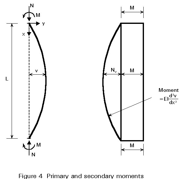
The moment at any point within the length may conveniently be regarded as being composed of two parts:
primary moment M
secondary moment Nv
Analysing this problem elastically using strut theory gives the maximum deflection at the centre as:
vmax = ![]() (5)
(5)
where PEy = ![]() is the Euler load for major axis buckling
is the Euler load for major axis buckling
and the maximum moment is:
Mmax = ![]() (6)
(6)
In both equations the secant term may be replaced by noting that the first order deflection (due to the end moments M acting alone) and the first order moment M - determined by ordinary beam theory - are approximately amplified by the term:
1/(1 - N/PEy) (7)
as shown in Figure 5.
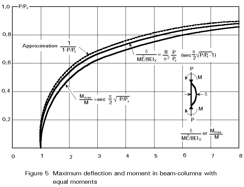
Thus:
vmax = (ML2/8EIy) {1/[1 - N/PEy]} (8)
Mmax =  (9)
(9)
Since the maximum elastic stress will be:
smax = sc + sb M/Mmax (10)
Equation (10) may be rewritten as:
![]() = 1,0 (11)
= 1,0 (11)
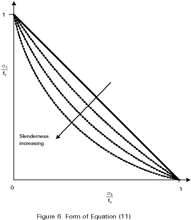
Equation (11) may be solved for values of sc and sb that just cause yield, taking different values of PEy (which is dependent on slenderness L/ry). This gives a series of curves, as shown in Figure 6, which indicate that as sb ® 0, sc tends to the value of material strength fy. Thus Equation (11) does not recognise the possibility of buckling under pure axial load at a stress sEy given by:
sEy = PEy / A (12)
= p2EIy/AL2 = p2Ey/l2 (13)
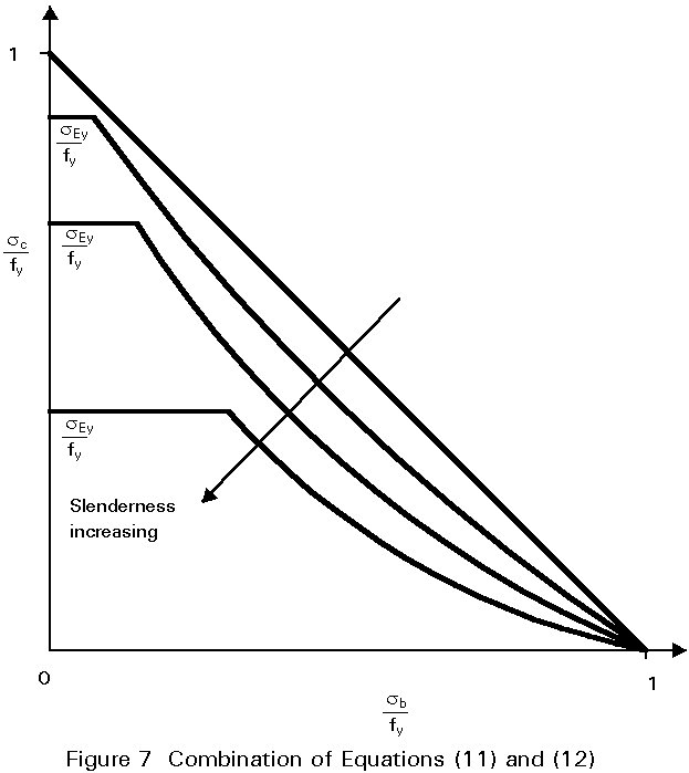
Use of both Equation (11) and Equation (12) ensures that both conditions are covered as shown in Figure 7.
Equations (11) and (13) are written in terms of stresses and originate from the concept of "failure" being defined as either the attainment of first yield or elastic buckling of the perfect member. Limit state design codes normally take ultimate load as the design criterion when considering resistance under static loading. Thus these equations must be re-written in terms of forces and moments. In doing this it is also necessary to make some allowance for those effects present in real steel structures that have not so far been explicitly allowed for, e.g. initial lack of straightness, residual stresses, etc.. For consistency in design it is, of course, essential that the interaction equation for combined loading reduces down to the column and beam design procedures as moment and axial load respectively reduce to zero.
The approach taken in Eurocode 3 [1] (assuming bending about the y-axis) is to use:
![]() £ 1 (14)
£ 1 (14)
in which cy is the reduction factor for column buckling
ky is a coefficient
The value of ky depends in a rather complex way on:
When all of these combine in the most severe way the safe value of ky is 1,5. The role of ky is to allow for the secondary bending effect described earlier plus the effects of non-uniform moment and spread of yield. Figures 8 - 10 show how, depending upon the particular case selected, the form of interaction may vary from concave to convex. In constructing these figures use has been made of the design formulae of Clause 5.5.4(1) of Eurocode 3 [1].
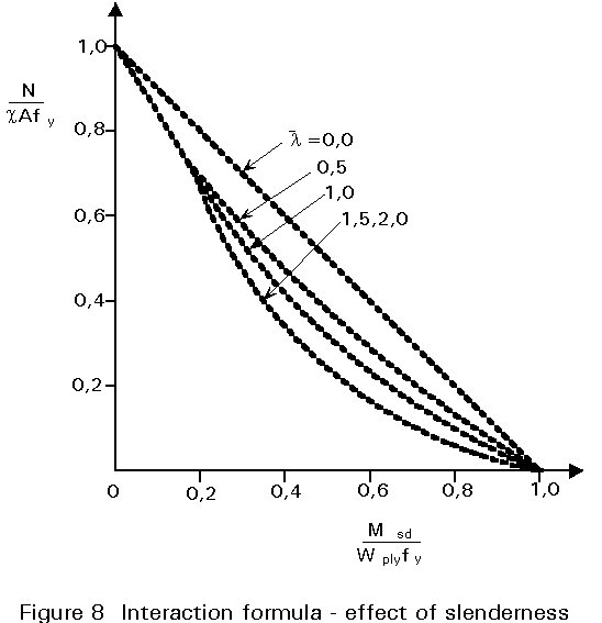
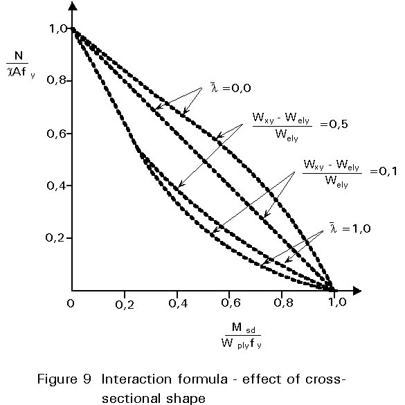
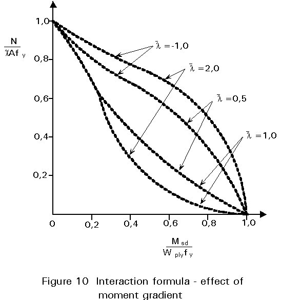
Figure 4 showed how, for the particular case of equal and opposite end moments, the primary moments are amplified due to the effect of the axial load N acting through the lateral displacements v. When the pattern of primary moment is different the two effects will not be so directly additive since maximum primary and secondary moments will not necessarily occur at the same location. Figure 11 illustrates the situation for end moments M and yM, where y can adopt values between +1 (uniform single curvature) and -1 (double curvature). The particular case shown corresponds to a y value » -0,5.
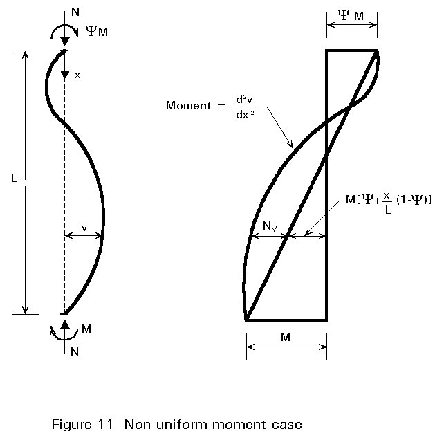
For the case illustrated the maximum moment still occurs within the member length but the situation is clearly less severe than that of Figure 4 assuming all conditions to be identical apart from the value of y. It is customary to recognise this in design by reducing the contribution of the moment term to the interaction relationship. Thus in Eurocode 3 "ky" in Equation (14) depends upon the ratio y, as already shown in Figure 10. The exact way in which this should be implemented is explained in Clause 5.5.4 and Figure 5.5.3 of Eurocode 3 [1].
Since the case of uniform single curvature moment is the most severe, it follows that a safe simplification is always to use the procedure for y = 1.0.
Returning to Figure 11, it is possible for the point of maximum moment to be at the end at which the larger primary moment is applied. This would usually occur if the axial load was small and/or slenderness was low so that secondary bending effects were relatively slight. In such cases design will be controlled by the need to ensure adequate cross-sectional resistance at this end. The formula from Table 1, for the particular shape of cross-section being used, should therefore be employed. In cases where only the uniform moment (y = 1,0) arrangement is being considered, the overall bucking check of Equation (14) will always be more severe than (or in the limit equal to) the cross-sectional check.
[1] Eurocode 3: "Design of Steel Structures": ENV 1993-1-1: Part 1.1: General rules and rules for buildings, CEN, 1992.
Comprehensive treatment of the beam-column problem for the in-plane case, with an emphasis on methods of analysis for the determination of the maximum load carrying capacity.
Chapter 7 refers to beam-columns, including a comparison of the subject's treatment in three design codes (not including Eurocode 3).
Gives basis of original European approaches to the use of interaction formulae, including derivations.
Chapter 8 presents a comprehensive review of theoretical, experimental and design-oriented contributions to the topic of beam-column behaviour.
Chapter 24 deals with beam-column behaviour and design, including explanations of the physical significance of the concepts of interaction and slenderness.
Chapter 6 deals with beam-column behaviour and design.
|
Cross-Section
|
Expression for MN |
|
|
Rolled I or H |
MN,y = 1,11 Mpl.y (1-n)
|
|
|
MNz = 1,56Mpl.z (1-n)(n+0,6)
|
||
|
Square hollow section |
MN = 1,26Mpl(1-n)
|
|
|
Rectangular hollow section |
MNy = 1,33Mpl.y(1-n)
|
|
|
MNz = Mpl.z(1-n)/(0,5 + ht/A)
|
||
|
Circular hollow section |
MN = 1,04Mpl(1-n1,7) |
Table 1 Expressions for reduced plastic moment resistance MN