ESDEP WG 7
ELEMENTS
To derive the basic theory of elastic lateral-torsional buckling and to discuss the physical significance of the resulting expressions.
Simple bending theory
Simple torsion theory
Lecture 6.4: General Methods for Assessing Critical Loads
Lectures 7.5: Columns
Lecture 7.9.1: Unrestrained Beams I
Lectures 7.10: Beam Columns
Worked Example 7.9: Laterally Unrestrained Beams
This lecture presents the basic elastic theory for lateral-torsional buckling of beams, commencing with the case of a simply supported beam under uniform moment. Variations in load pattern, load level and degree of end restraint are discussed. The theoretical derivations are separated into two Appendices, the main text being limited to a discussion of the underlying assumptions and the physical significance of the derived expressions.
b flange width
C1 coefficient to allow for type of loading
hf distance between flange centroids
EIw warping rigidity
EIz minor axis flexural rigidity
E Young's modulus
F applied load
Fcr elastic critical buckling load
GIt torsional rigidity
d overall depth of section
L span
M moment
Mcr applied elastic critical buckling moment
tf flange thickness
tw web thickness
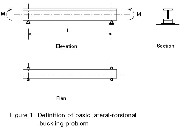
The basic model used to illustrate the theory of lateral-torsional buckling is shown in Figure 1. It assumes the following:
This problem may be regarded as being analogous to the basic pin-ended Euler strut.
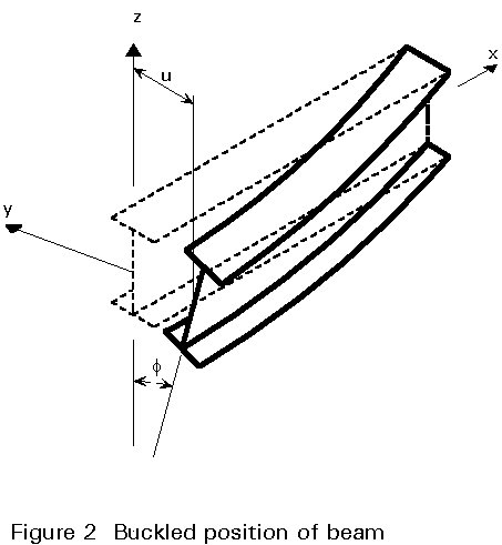
The beam is placed in its buckled position, as in Figure 2, and the magnitude of the applied load necessary to hold it there determined by equating the disturbing effect of the end moments, acting through the buckling deformations, to the internal (bending and torsional) resistance of the section.
The derivation and solution to the equations leading to the critical value of applied end moments (Mcr) at which the beam of Figure 1 just becomes unstable is provided in Appendix 1. The physical significance of the solution and its application in cases where the assumptions listed above do not apply are discussed in Sections 2 and 3 that follow.
The buckled shape of the beam, Figure 2, is now compared with the expression for the elastic critical moment of Equation (17) in Appendix 1, i.e.
Mcr =  (17)
(17)
The presence of the flexural (EIz) and torsional (GIt and EIw) stiffnesses of the member in the equation is a direct consequence of the lateral and torsional components of the buckling deformations. The relative importance of the two mechanisms for resisting twisting is reflected in the second square root term. Length is also important, entering both directly and indirectly via the p2EIw/L2GIt term. It is not possible to simplify Equation (17) by omitting terms without imposing limits on the range of application of the resulting approximate solution. Figure 6 shows quantitatively the application of Equation (17) to the different types of beam sections defined in the earlier Lecture 7.8.1. The region of the curves for both I-sections of low length/depth ratios corresponds to the situation in which the value of the second square root term in Equation (17) adopts a value significantly in excess of unity. Since warping effects (see Appendix 1) will be most important for deep sections composed of thin plates, it follows that the p2EIw/L2GIt term will, in general, tend to be large for short deep girders and small for long shallow beams.
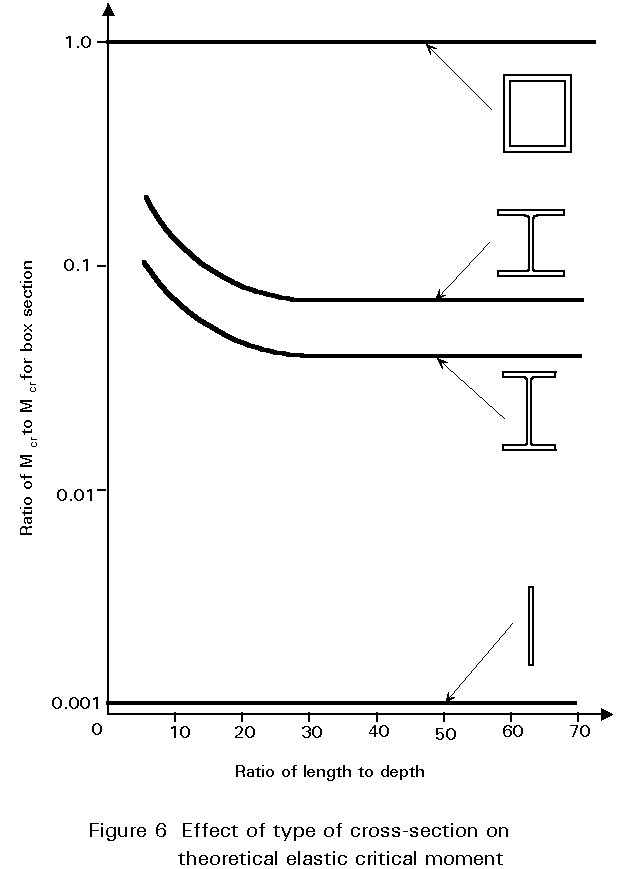
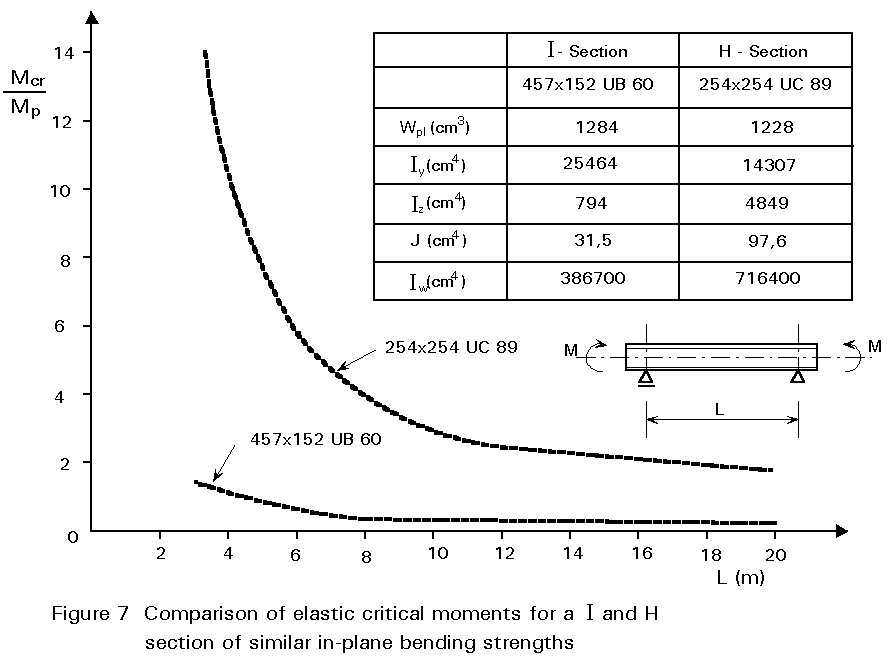
Figure 7 gives some quantitative indication of the effect of shape of cross-section for structural steel I-beams, by comparing values of Mcr for a beam (I) and a column (H) having approximately equal in-plane plastic moment capacities. Clearly, lateral-torsional buckling is a potentially more significant design consideration for the beam section which is much less stiff laterally.
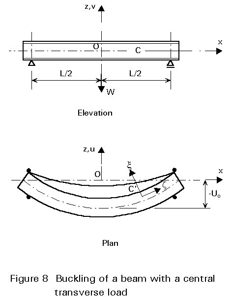
The equivalent of Equation (8) (Appendix 1) may be set up and solved for a variety of other load cases. Since the applied moment at any point within the span will now be a function of x, the mathematics will be more complex. As an example, consider the beam subjected to a central load acting at the level of the centroidal axis shown in Figure 8, for which the analysis is outlined in Appendix 2.
The solution for this example may conveniently be compared with the basic case in terms of the critical moments for each, i.e. maximum moment when the beam is on the point of buckling.
Basic case: Mcr = (p/L) Ö(EIxGIt) Ö[1+ (p2EIw/L2GIt)] (17)
Central load: Mcr = (4,24/L) Ö(EIxGIt) Ö[1+ (p2EIw/L2GIt)] (21)
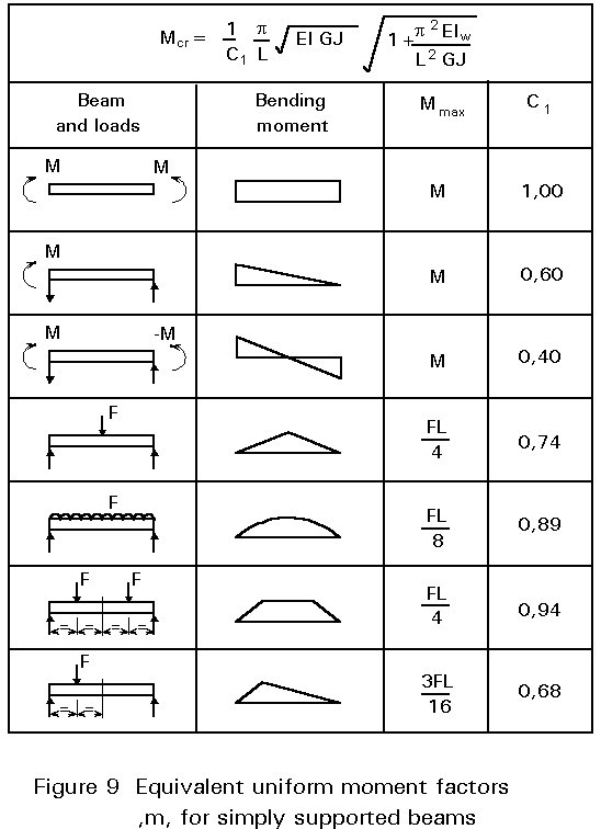
The ratio of the two constants p/4,24=0,74 is the reciprocal of the coefficient C1 introduced in Lecture 7.9.1. Its value is a direct measure of the severity of a particular pattern of moments relative to the basic case.
Figure 9, which gives C1 factors for various loading patterns, shows how lateral stability generally increases as the moment pattern becomes less uniform.
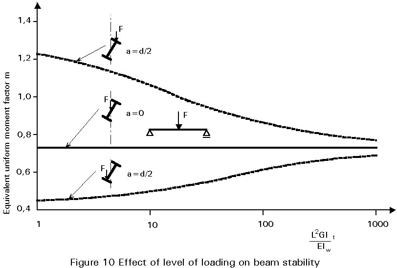
For transverse loads free to move sideways with the beam as it buckles, the level of application of load (relative to the centroid) is important. The solution for a point load applied at any level relative to the beam's centroidal axis may conveniently be obtained using an energy approach, as outlined in Appendix 2. When the load is applied to either the top flange or the bottom flange, e.g. by a crane trolley, the solution of Equation (21) may still be used, providing the numerical constant is replaced by a variable, the value of which depends upon the ratio L2GIt/EIw as shown in Figure 10. The reason why top flange loading and bottom flange loading are respectively more or less severe than centroidal loading may be appreciated from the sketches in Figure 10, which show the destabilising and stabilising effects. Clearly this would be expected to become more significant as the depth of the section increases and/or the span reduced, i.e. as L2GIt/EIw becomes smaller.
It has already been suggested in Lecture 7.9.1, that lateral support arrangements which inhibit the growth of the buckling deformations will improve a beam's lateral stability. Equally, less effective conditions will reduce stability. Providing the appropriate boundary conditions can be incorporated into the analysis methods of Appendices1 and 2, any arrangement can be dealt with.
A convenient way of including the effect of different support conditions is to redefine L in Equation (17) as an effective length l, with the exact value of l/L depending upon the degree of lateral bending and/or warping restraint provided. In Eurocode 3 [1] this approach is split into the use of two factors:
k referring to end rotation on plan.
kw referring to end warping.
It is recommended that kw be taken as unity unless special provision for warping fixity is made; k may vary from 0,5 for full fixity, through 0,7 for one end fixed and one end free, to 1,0 for no rotational fixity.
One case of particular practical interest is the cantilever, for which some results are presented in Figure 11.
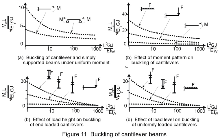
These show that:
Continuity may be present in two different forms:
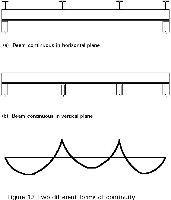
For the first case a safe design will result if the most critical segment, treated in isolation, is used as the basis for designing the whole beam. For the second case account should be taken of the actual moment diagram within each span, produced by the continuity, by using the C1 factor. If the top flange can be considered as laterally restrained because of attachment to a concrete slab, particular attention should be paid to the regions in which the lower flange is in compression, e.g. the support regions or regions where uplift loads can occur.
The basic theoretical solution of Equation (17) is valid for members that are symmetrical about their horizontal axis, e.g. a channel with the web vertical, providing the moments act through the shear centre (which will not now coincide with the centroid). However, sections symmetrical only about the vertical axis, e.g. an unequal flanged I, require some modification so as to allow for the so-called Wagner effect. This arises as a direct result of the vertical separation of the shear centre and the centroid and leads to either an increase or a decrease in the section's torsional rigidity. Thus lateral stability will be improved when the larger flange is in compression and reduced when the smaller flange is in compression as compared with equal flange sections having comparable properties.
Sections with no axis of symmetry will not actually buckle but will deform by bending about both principal axes and by twisting from the onset of loading. They should therefore be treated in the same way as symmetrical sections under biaxial bending.
The elastic critical moment for a doubly symmetrical I-beam provided with continuous elastic torsional restraint, of stiffness equal to Kf , is:
Mcr = 
Rearranging this shows that the beam behaves as if its torsional rigidity GIt were increased to (GIt+ Kf L2/p 2), thereby permitting a ready assessment of the effectiveness of the restraint. An important practical example of such a restraint would be that provided by the bending stiffness of profiled steel sheeting (used typically in roof construction) spanning at right angles to the beam.
[1] Eurocode 3: "Design of Steel Structures": ENV 1993-1-1: Part 1.1: General rules and rules for buildings, CEN, 1992.
Chapters 1 - 3 deal with various aspects of behaviour and design of laterally unrestrained beams.
Chapter 3 deals with laterally unrestrained beams.
Basic derivations for the elastic critical moment for a variety of beam problems are provided in Chapter 6.
Chapter 4 presents the basic theory of lateral buckling of beams.
Chapter 2 deals with the fundamentals of elastic behaviour, whilst Chapter 3 covers elastic and inelastic behaviour and design of laterally unrestrained beams.
Laterally unrestrained beams are dealt with in Chapter 6.
APPENDIX 1: ANALYSIS OF LATERAL-TORSIONAL BUCKLING
Derivation of Governing Equations
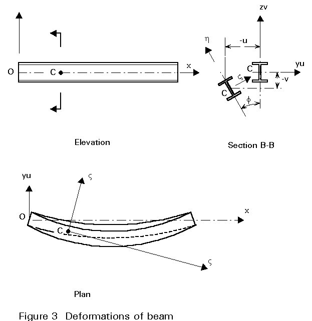
The deformed state of the beam is shown in Figure 3, which identifies the deflections (u and v) and the twist (f). A new co-ordinate system x h z , which deflects with the beam, is also illustrated.
Bending in the x z and h z planes and twisting about the z axis are governed by:
EIy ![]() (1)
(1)
EIz ![]() (2)
(2)
GIt ![]() (3)
(3)
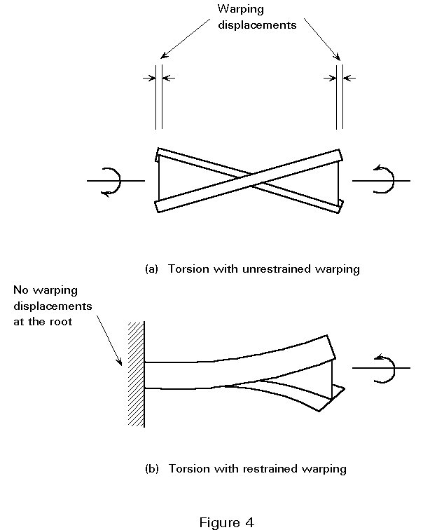
In Equations (1) and (2) the flexural rigidities and curvatures in the x z and the h z planes have been replaced by the values for the yx and zx planes, on the basis that f is a small angle. Equation (3) includes both mechanisms available in a thin-walled section to resist twist; the first term corresponds to that part of the applied torque which is resisted by the development of shear stresses, whilst the second term allows for the influence of restrained warping. This latter phenomenon arises as a direct result of the type of axial flange deformation, illustrated in Figure 4a, that occurs in an I-section subject to equal and opposite end torques. The two flanges tend to bend in opposite senses about a vertical axis through the web, with the result that originally plane sections do not remain plane. On the other hand, for the cantilever of Figure 4b, it is clear that warping deformations must be at least partly inhibited elsewhere along the span, since they cannot occur at the fixed end. This induces additional axial stresses in the flanges; the pair of couples, or bimoment, due to this additional stress system provides part of the section's resistance to twist. In the case of lateral instability, restraint against warping arises as a result of adjacent cross-sections wanting to warp by different amounts.
For an I-section, the relative magnitudes of the warping constant Iw and the torsion constant It are:
Iw = Iz hf2/4 and It = ![]()
They will be affected principally by the thickness of the component plates and by the depth of the section. For compact column-type sections the first term in Equation (3) will tend to provide most of the twisting resistance, whilst the second term will tend to become dominant for deeper beam shapes.
Consideration of the buckled shape using Figures 2, 3 and 5 enables the components of the applied moment in the x z and h z planes and about the z axis to be obtained as:
Mx = Mcosf , Mh = Msinf , Mz = Msina (4)
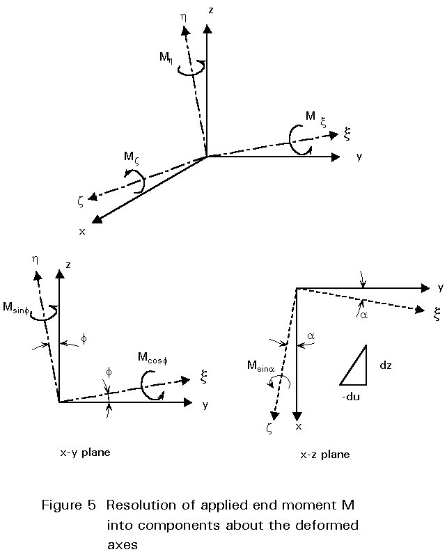
Since f is small, cosf » 1 and sinf » f, whilst
Figure 5 shows that sina may be approximated by -![]() . Thus Equations (1) - (3) may be written as:
. Thus Equations (1) - (3) may be written as:
EIy ![]() = M (5)
= M (5)
EIz ![]() = Mf (6)
= Mf (6)
GIt ![]() (7)
(7)
Since Equation (5) contains only the vertical deflection (v), it is independent of the other two; it controls the in-plane response of the beam described in Lecture 7.5.1. Equations (6) and (7) are coupled in u and f , the buckling deformations; their solution gives the value of elastic critical moment (Mcr) at which the beam becomes unstable. Combining them gives:
EIw ![]() (8)
(8)
Solution
The solution of Equation (8) is made far simpler if the warping stiffness (Iw) is assumed to be zero. The results obtained are then directly applicable to beams of narrow rectangular cross-section but are conservative for the normal range of I-sections. Equation (8) therefore reduces to:
 (9)
(9)
Putting m2 = ![]() enables the solution to be written as:
enables the solution to be written as:
f
= Acos mx = Bsin mx (10)Noting the boundary conditions at both ends gives
When x = 0, f = 0; then A = 0 (11)
When x = L, f = 0; then Bsin mL = 0
and either B = 0, or (12)
sin mL = 0 (13)
The first possibility gives the unbuckled position whereas the second gives:
m
L = 0, p, 2p (14)and the first non-trivial solution is:
m
L = p (15)which gives:
Mcr = (p/L) Ö(EIxGIt) (16)
Since the form of Equation (9) is identical to the form of the basic Euler strut equation all of the same arguments about its solution apply.
Returning to the original Equation (8), this may be solved to give:
Mcr = (p/L) Ö(EIxGIt) Ö[1+ (p2EIw/L2GIt)] (17)
The inclusion of warping effects therefore enhances the value of Mcr by an amount which is dependent on the relative values of EIw and GIt.
APPENDIX 2: BUCKLING OF A CENTRALLY LOADED BEAM
Using the approach of Appendix 1 and noting from Figure 7 that the vertical load will produce a moment about the x-axis of W(uo - u)/2 when the beam is in its buckled position, enables Equations (4) to be re-written as:
Mx = ![]()
Mh = ![]() (18)
(18)
Mz = ![]()
Replacing Equations (5) - (7) by their revised forms and eliminating u from the second and third of these gives:
EIw ![]() (19)
(19)
which may be solved for Wcr to yield approximately:
Wcr = 5,4  (20)
(20)
The moment at midspan is then:
Mcr =  (21)
(21)
The alternative means of obtaining elastic critical loads uses the energy method, in which the work done by the applied load during buckling is equated to the additional strain energy stored as a result of the buckling deformations. Considering an element of the longitudinal axis of the beam of length dx located at C, bending in the x z plane causes the end B of the beam to rotate in the x z plane by:
![]() (22)
(22)
The vertical component of this is:
![]() (23)
(23)
Summing these for all elements between x= 0 and x = L/2 gives the lowering of the load W from which the work is:
 (24)
(24)
The strain energy stored as a result of lateral bending, twisting and warping is:
 (25)
(25)
Assuming a buckled shape of the form:
![]() (26)
(26)
and equating Equations (24) and (25) enables the critical value of W to be obtained.
Use of this technique permits examination of the case in which the load is applied at a level other than the centroidal axis. Assuming W to act at a vertical distance (a) above the centroid, the additional work will be:
Wa (1 - cos fo) = Wa fo2/2
in which fo is the value of f at the load point. This must be added to Equation (24).