ESDEP WG 7
ELEMENTS
To extend the introductory coverage of beam columns given in Lecture 7.10.1 to cover the full three-dimensional case.
Simple bending and torsion theory
Lecture 7.2: Cross-Section Classification
Lectures 7.5: Columns
Lectures 7.8: Restrained Beams
Lectures 7.9: Unrestrained Beams
Lecture 7.10.1: Beam columns I
Lecture 7.11: Frames
Worked Example 7.10: Beam Columns
This lecture expands on the treatment of beam-columns given in Lecture 7.10.1 to include the cases of out-of-plane buckling and biaxial bending. The basis for the Eurocode 3 interaction formulae is discussed and related to physical behaviour [1].
Lecture 7.10.1 introduced all the main aspects of beam-column behaviour and design within the context of the uniaxial in-plane case. More general forms of response are, however, possible. This lecture broadens the coverage to include all of the main cases.
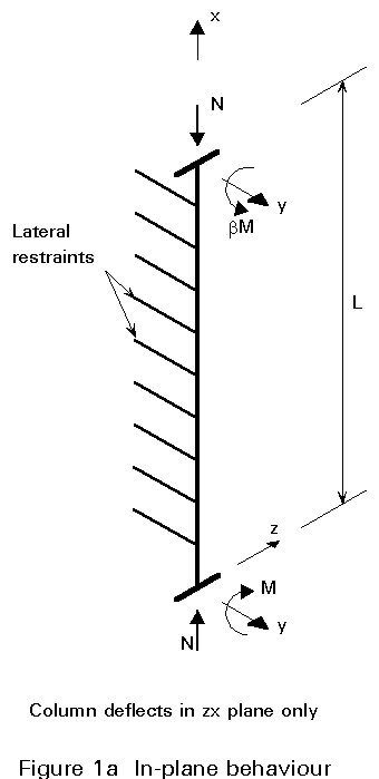
Three separate forms of beam-column behaviour are illustrated in Figure 1.
If the member is bent about its weaker principal axis, or is prevented from deflecting laterally when bent about its stronger principal axis as shown in Figure 1a, then its response will be confined to the plane of bending. This case has been covered in Lecture 7.10.1.
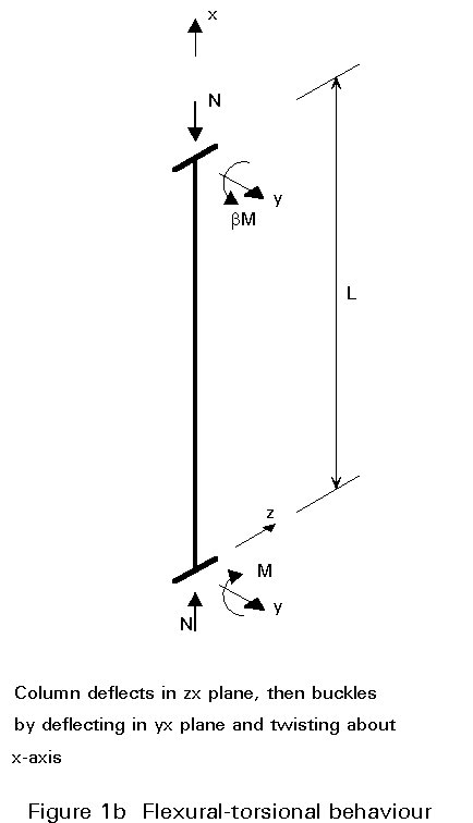
When a laterally unbraced beam-column of open cross-section is bent about its stronger principal axis as shown in Figure 1b, then it may buckle prematurely out of the plane of loading by deflecting laterally and twisting. Such behaviour is conceptually and mathematically very similar to the lateral-torsional buckling of beams described in Lectures 7.9.1 and 7.9.2.
The most general situation is illustrated in Figure 1c. When bending is applied about both principal axes the member's response will be 3-dimensional in nature, involving biaxial bending and twisting.
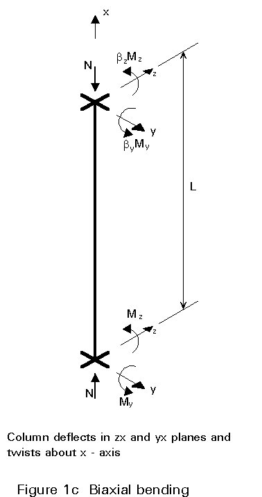
In Figure 1 the nature of the interaction in each case is listed in the caption. Clearly the behaviour shown as Figure 1c is the most general, with that of Figures 1a and 1b being simpler and more limited cases. For a full treatment of the in-plane case of Figure 1a refer back to Lecture 7.10.1.
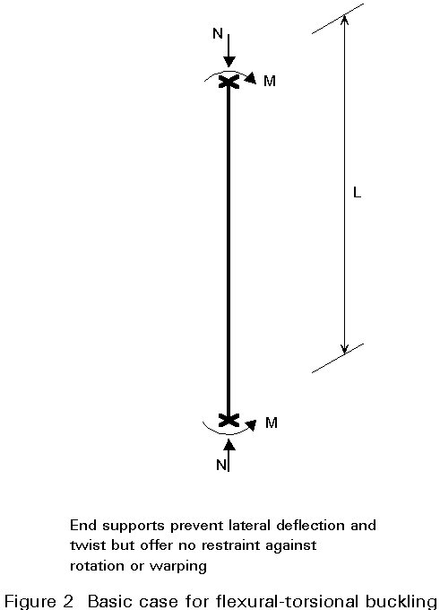
When a laterally unrestrained I-section beam-column is bent about its major axis, it may buckle by deflecting laterally and twisting at a load which is significantly less than the maximum load predicted by an in-plane analysis. Assuming elastic behaviour and the arrangement of applied loading and support conditions given in Figure 2, the critical combinations of N and M may be obtained from the solution of:
![]() =
= ![]() (1)
(1)
in which io = [(Iy + Iz)/A]1/2 is the polar radius of gyration
Nz = p2 EIz/L2 is the minor axis critical load
No = (GJ/io2) (1 + p2 EIw/GItL2) is the torsional buckling load
Equation (1) reduces to the buckling of a beam when N ® 0 and to the buckling of a column in either flexure (Nz) or torsion (No) as M ® 0. In the first case the critical value of M will be given by:
Mcr =  (2)
(2)
in which EIz is the minor axis flexural rigidity
GIt is the torsional rigidity
EIw is the warping rigidity
In deriving Equation (1) no allowance was made for the amplification of the in-plane moments M by the axial load acting through the in-plane deflections. As explained in Lecture 7.10.1 this may be approximated as M/(1-N/Ny). Equation (1) can, therefore, be modified to:
 (3)
(3)
Noting the relative magnitudes of Ny, Nz and No and re-arranging gives the following approximation:
N/Nz + {1/(1-N/Ny)}{M/i(NzNo)1/2} = 1 (4)
or
N/ Nz + {1/(1-N/ Ny)}M/Mcr = 1 (5)
For design purposes it is necessary to make suitable allowances for effects such as initial lack of straightness, partial yielding, residual stresses, etc., as has been fully discussed in earlier lectures in the context of columns and beams. Thus some modification to Equation (5) is necessary to make it suitable for design. In particular, the end points (corresponding to the cases of M = 0 and N = 0) must conform to the established procedures for columns (Lectures 7.5.1 and 7.5.2) and beams (Lectures 7.9.1 and 7.9.2).
Eurocode 3 [1] uses the interaction equation:
![]() £ 1 (6)
£ 1 (6)
In which kLT is a coefficient whose value depends upon:
and cLT is the reduction factor for lateral-torsional beam buckling.
For the most severe combination kLT adopts the value unity, corresponding to a linear combination of the compressive and bending terms. This reflects the reduced scope for amplification effects in this case, since the value of Nsd cannot exceed cz A fy, which will, in turn, be significantly less than the elastic critical load for in-plane bucking Ny.
It is, of course, also necessary to ensure against the possibility of in-plane failure by excessive deflection in the plane of the web at a lower load than that given by Equation (6). This might occur, for example, in situations where different bracing and/or support conditions are provided in the xy and xz planes as illustrated in Figure 3.
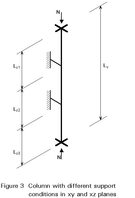
Such cases should be treated by checking, in addition to Equation (6), an in-plane equation of the form:
![]() £ 1 (7)
£ 1 (7)
in which cmin depends on the in-plane conditions. Usually, however, Equation (6) will govern.
Analysis for the full 3-dimensional case, even for the simple elastic version, is extremely complex and closed-form solutions are not available. Rather than starting analytically it is more convenient to approach the question of a suitable design approach from considerations of behaviour and the use of the methods already derived for the simpler cases of Figures 1a and 1b.
Figure 4 presents a diagrammatic version of the design requirement. The N-Mz and N-My axes correspond to the two uniaxial cases already examined. Interaction between the two moments Mz and My corresponds to the horizontal plane. When all three load components N, Mz and My are present the resulting interaction plots somewhere in the 3-dimensional space represented by the diagram. Any point falling within the boundary corresponds to a safe combination of loads.
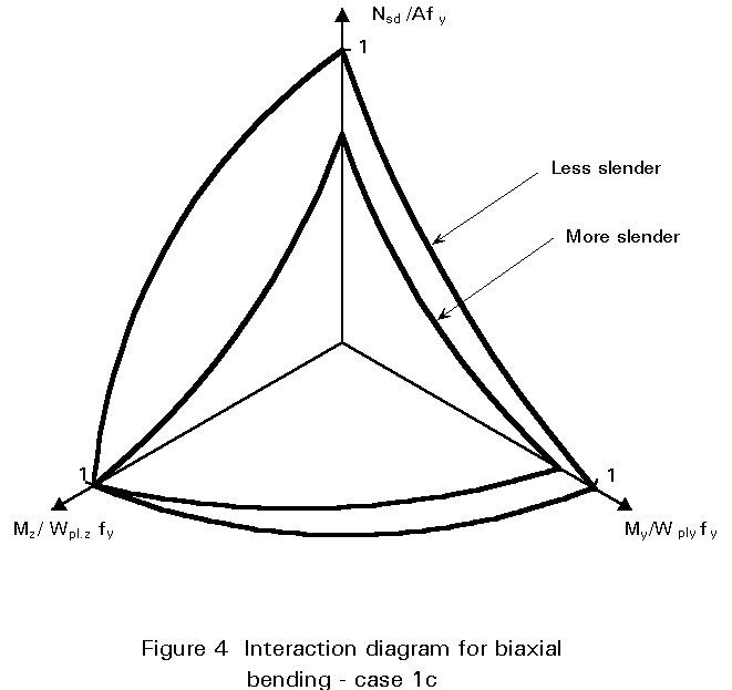
Assuming proportional loading any load combination may be regarded as a straight line starting at the origin, the orientation of which depends upon the relative sizes of the three load components. Increasing the loads extends this line from the origin until it just reaches and then exceeds the boundary. Non-proportional loading would correspond to a series of lines.
In each case the axes have been taken as the ratio of the applied component to the member's resistance under the load component alone, e.g. Nsd / cmin Afy in the case of the compressive loading. Thus Figure 4 actually represents the situation for one particular example with particular values of cross-sectional properties, slenderness and load arrangement. Changing some or all of these will alter the shape of the interaction surface shown, but not the general principle involved.
For design purposes, it is necessary to have a convenient representation of the situation described in Section 5 by using an interaction equation containing the three load components N, Mz and My. Parts of this equation, corresponding to the two 2-dimensional cases represented by the N, Mz and N, My planes, have already been discussed. The full equation must clearly reduce to these in the absence of the third load component.
Eurocode 3 [1] uses the pair of formulae:
![]() £ 1 (8)
£ 1 (8)
![]() £ 1 (9)
£ 1 (9)
Two checks are necessary because, under the action of compression plus major axis moment on an I-section with different support conditions in the zx and yx planes, it is not known whether the in-plane or out-of-plane interaction will be the more critical; that is to say whether, in the absence of Mz, failure would occur as shown in Figure 1a or Figure 1b. For the same conditions in both planes and ![]() z >
z > ![]() y, cmin will correspond to cz and Equation (9) will govern since cLT, the reduction factor for lateral-torsional buckling under pure bending, will be less than or (if
y, cmin will correspond to cz and Equation (9) will govern since cLT, the reduction factor for lateral-torsional buckling under pure bending, will be less than or (if ![]() LT is small) equal to unity.
LT is small) equal to unity.
For cross-sections not susceptible to lateral-torsional buckling, e.g. tubes, only Equation (8) is required since cLT = 1.
The design formulae given as Equations (6) - (9) relate specifically to the case of Class 1 or 2 sections, i.e. those for which the proportions of the plate elements meet the limitations necessary to ensure the development of full cross-sectional plasticity, as explained in Lecture 7.2. When using either Class 3 or Class 4 sections some modifications are necessary.
For Class 3 cross-sections the quantities Wpl.y and Wpl.z should be replaced by the equivalent elastic quantities Wel.y and Wel.z.
When Class 4 sections are being employed the section properties A and W must relate to the effective cross-section; the shift of the neutral axis of the effective cross-section from its original position due to loss of effectiveness of some parts of the cross-section must also be allowed for. Thus Equations (8) and (9) become:
![]() £ 1
(10)
£ 1
(10)
![]() £ 1
(11)
£ 1
(11)
in which Aeff, Weff.y and Weff.z are the effective properties in the presence of only uniform compression or moment about the y and z axes respectively and eN is the shift of the neutral axis when the cross-section is subject to uniform compression.
An important point to note from the definition of Aeff and Weff above is that the calculation of cross-sectional properties, and thus also cross-sectional classification, should be undertaken on a separate basis for each of the three load components N, My and Mz. This does, of course, mean that the same member may be classified as (say) Class 1 for major-axis bending, Class 2 for minor-axis bending and Class 3 for compression. In such cases the safe design approach is to conduct all beam-column checks using the procedures for the least favourable class.
The value of kLT for use in Equation (6) is actually given by:
![]() (but kLT £ 1)
(12)
(but kLT £ 1)
(12)
in which mLT = 0,15![]() z bM.LT - 0,15
(but mLT £ 0,90)
(13)
z bM.LT - 0,15
(but mLT £ 0,90)
(13)
and bM.LT is the equivalent uniform moment factor for lateral-torsional buckling determined from Table 2.
In Equations (7) - (11) the values of ky and kz should be obtained from:
k = ![]() but k £ 1,15
(14)
but k £ 1,15
(14)
m
=in which m, c, ![]() , bM, Wpl and Wel all relate to the axis under consideration, i.e. y or z, and bM is determined from Table 2.
, bM, Wpl and Wel all relate to the axis under consideration, i.e. y or z, and bM is determined from Table 2.
For Class 3 or 4 cross-sections the second term in Equation (15) should be omitted.
If allowance has been made when determining the k-factors (through the use of bM) for the less severe effect of patterns of moment other than uniform single curvature bending, it is necessary further to check that the cross-section is everywhere capable of locally resisting the combination of compression and primary moment(s) present at any point. This location will usually be one or other of the ends as explained in Lecture 7.10.1.
Expressions for checking several types of cross-section under compression plus uniaxial bending were given in Lecture 7.10.1. For biaxial bending Eurocode 3 [1] uses:
 £ 1 (16)
in which the values of a and b depend upon the type of cross-section as indicated in Table 1.
A simpler but conservative alternative is:
![]() £
1 (17)
£
1 (17)
[1] Eurocode 3: "Design of Steel Structures": ENV 1993-1-1: Part 1.1: General rules and rules for buildings, CEN, 1992.
Comprehensive treatment of the beam-column problem for the cases of flexural-torsional bucking and biaxial bending.
Chapter 7 refers to beam-columns, including a comparison of the subject's treatment in three design codes (not including Eurocode 3).
Gives basis of original European approaches to the use of interaction formulae, including derivations.
Chapter 8 presents a comprehensive review of theoretical, experimental and design-oriented contributions to the topic of beam-column behaviour.
Chapter 24 deals with beam-column behaviour and design, including explanations of the physical significance of the concepts of interaction and slenderness.
Chapter 6 deals with beam-column behaviour and design.
|
Type of cross-section |
a |
b |
|
I and H - sections Circular tubes Rectangular hollow sections Solid rectangles and plates |
2 2
1,73 + 1,8n3 |
5n but ³ 1 2
1,73 + 1,8n3 |
|
n = Nsd / Npl.Rd |
||
Table 1 Values of a and b for use in Equation (16)
|
Moment diagram |
Equivalent uniform moment factor b M |
|
End moments |
bM,y = 1,8 - 0,7 y |
|
Moments due to in-plane lateral loads |
bM,Q = 1,3 bM,Q = 1,4 |
|
Moments due to in-plane lateral loads plus end moments |
bM = bm, y
+ MQ = ½ Max M½ due to lateral load only
DM = ½ Max M½ for moment diagram without change of sign DM = ½ Max M½ + ½ Min M½ where sign of moment diagram changes
|
Table 2 Equivalent uniform moment factors bM


