ESDEP WG 7
ELEMENTS
To derive and discuss the procedures used to design restrained compact beams for bending, shear and deflection, according to the principles of Eurocode 3 [1].
Elastic theory for uniaxial bending
Simple torsion theory
Lecture 7.2: Cross-Section Classification
Lecture 7.8.2: Restrained Beams II
Lectures 7.9: Unrestrained Beams
Worked Example 7.8: Laterally Restrained Beams
This lecture is restricted to beams whose design may be based on simple strength of materials considerations. Behaviour in simple bending is discussed, leading to the concept of section modulus as the basis for strength design. Subsidiary considerations of shear strength, resistance to local loads and adequate stiffness against deflection are also mentioned. Behaviour under complex loading, producing bending about both principal axes, or combined bending and torsion is introduced.
A area
Av shear area
d depth of section
F applied load
fd limiting stress in material
fy material yield strength
fyd material design strength
I second moment of area
M moment
Mpl plastic moment
t thickness
tf thickness of flange
tw thickness of web
Vs shear due to applied load
W elastic section modulus
Wmax maximum value of W
Wmin minimum value of W
Wpl plastic section modulus
a
,b coefficients, see Equation (7)s
normal stressProbably the most basic structural component is the beam, spanning between two supports, and transmitting loads principally by bending action. Steel beams, which may be drawn from a wide variety of structural types and shapes, can often be designed using little more than the simple theory of bending. However, situations will arise in which the beam's response to its loading will be more complex, with the result that other forms of behaviour must also be considered. The main purpose of this lecture is to concentrate on the design of that class of steel beam for which strength of materials forms the basis of the design approach. These are termed "restrained compact beams"; in order to come within this category the beam must not be susceptible to either local instability (see Lecture 7.2 for Class 4 beams) or lateral-torsional instability (see Lecture 7.9.1 and 7.9.2 for unrestrained beams). A further limitation is that the beams are assumed to be statically determinate or, if statically indeterminate, that the distribution of internal bending moments has been obtained on a simple linear elastic basis.
The first requirement will be met if the width of the individual plate elements of the cross-section are limited, relative to their thickness. Sections for which the ratios of flange width/flange thickness, web depth/web thickness etc, have been limited, so that their full plastic moment capacity may be achieved, correspond to either Class 1 or Class 2 according to Eurocode 3 [1]. The majority of hot rolled sections, e.g. UB's and IPE's, meet these requirements. However, care is necessary when using fabricated sections and suitable rules are provided in codes of practice. This lecture assumes that the beam cross-section will at worst correspond to Class 2 or Class 3 and that, if it meets the Class 1 limits, then the global analysis of the structure will be conducted using plastic methods.
Lateral-torsional instability will not occur if any of the following conditions apply:
For the special case of continuous beams supporting a roof or floor, care must be taken to ensure adequate stability of those regions in which the bottom flange is in compression, e.g.the support region under gravity loading, the mid-span region under wind uplift, etc... For the purpose of this lecture, beams within any of these categories will be classed as "restrained".
Several factors, some of them tending to conflict with one another, influence the designer's choice of beam type for a given application. Clearly the beam must possess adequate strength, but it should also not deflect too much. It must be capable of being connected to adjacent parts of the structure; this will often involve the use of site connections which should be simple and quick to erect, with minimum requirements for skilled labour or special equipment. Particular features, such as the passage of services beneath the floor of a building, may dictate the use of a section with openings in the web, whilst architectural requirements may require the profile to be varied, to improve the line. Table 1, summarising the main types of steel beam, indicates the range of spans for which each is most appropriate and gives some idea of any special features.
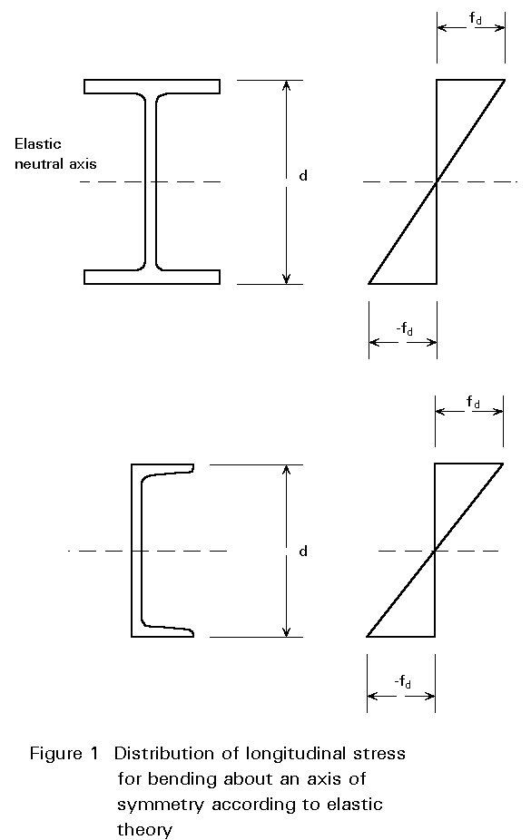
For a doubly-symmetrical section or a singly-symmetrical section bent about the axis of symmetry, the basic theory of bending, assuming elastic behaviour, gives the distribution of bending stress shown in Figure 1.
Since the maximum stress smax is given by:
smax = ![]() (1)
(1)
where M is the moment at cross-section under consideration.
d is the overall depth of section.
I is the second moment of area about the neutral axis (line of zero strain).
it follows that limiting this to a fraction of the material yield stress gives a design condition of the form:
W ³ M/fd (2)
where W = ![]()
fd is the limiting normal bending stress.
When M is taken as the moment produced by the working loads, this approach to design is termed 'elastic' or 'permissible stress' design and is the method traditionally used in many existing codes of practice. In more modern Limit States codes fd is taken as the material strength fy possibly divided by a suitable material factor gM and M is taken as the moment due to the factored loads i.e. the working loads suitably increased so as to provide a margin of safety in the design. Equation (2), in this case, represents the condition of first yield. Values of W for the standard range of sections are available in tables of section properties.
Selection of a suitable beam therefore comes down to:
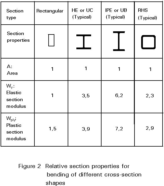
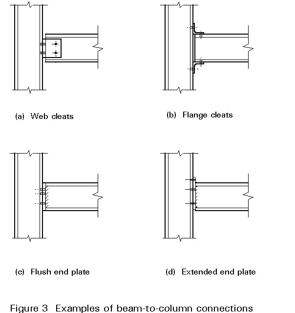
Clearly, sections for which the majority of the material is located as far away as possible from the neutral axis will tend to be the most efficient in elastic bending. Figure 2 gives some quantitative idea of this for some of the more common structural shapes. I-sections are most often chosen for beams because of their structural efficiency; being open sections they can also be connected to adjacent parts of the structure without undue difficulty. Figure 3 gives some typical examples of beam-to-column connections.
Utilisation of the plastic part of the stress-strain curve for steel enables moments in excess of those which just cause yield to be carried. At full plasticity the distribution of bending stress in a doubly-symmetrical section will be as illustrated in Figure 4, with half the section yielding in compression and half in tension.
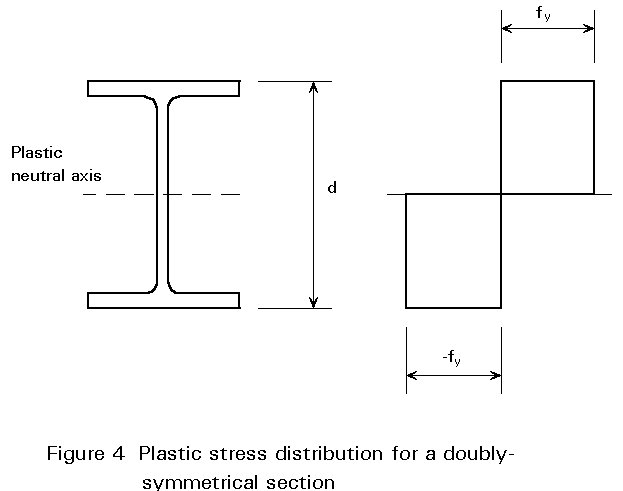
The corresponding moment is termed the fully plastic moment Mpl. It may be calculated by taking moments of the stress diagram about the neutral axis to give:
Mpl = fy Wpl (3)
where fy is the material yield stress (assumed identical in tension and compression).
Wpl is the plastic section modulus.
Basing design on Equation (3) means that the full strength of the cross-section in bending is now being used, with the design condition being given by:
Wpl ³ M/fyd (4)
where M is the moment at cross-section under consideration.
fyd is the design strength (material yield strength divided by a suitable material factor).
When M is due to the factored loads Equation (4) represents the design condition of ultimate bending strength used in Eurocode 3 for beams whose cross-sections meet at least the Class 2 limits [1]. It is usual in codes such as Eurocode 3 for the value of fyd to be taken as the material yield strength, reduced slightly so as to cover possible variations from the expected value.
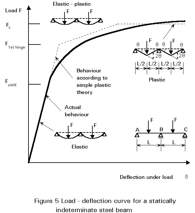
For continuous (statically indeterminate) structures, attainment of Mpl at the point of maximum moment will not normally imply collapse. Providing nothing triggers unloading at this point, e.g. local buckling does not occur, then the local rotational stiffness will virtually disappear, i.e. the cross-section will behave as if it were a hinge, and the pattern of moments within the structure will alter from the original elastic distribution as successive plastic hinges form. This redistribution of moments will enable the structure to withstand loads beyond that load which produces the first plastic hinge, until eventually collapse will occur when sufficient hinges have formed to convert the structure into a mechanism, as shown in Figure 5. Utilisation of this property of redistribution is termed "plastic design". It can only be used for continuous structures and then only when certain restrictions on cross-sectional geometry, member slenderness, etc.., are observed. The topic is covered in detail in Lecture 7.8.2 in the context of beams and in Lecture 7.11 in the context of frames.
Although bending will govern the design of most steel beams, situations will arise, e.g. short beams carrying heavy concentrated loads, in which shear forces are sufficiently high for them to be the controlling factor.
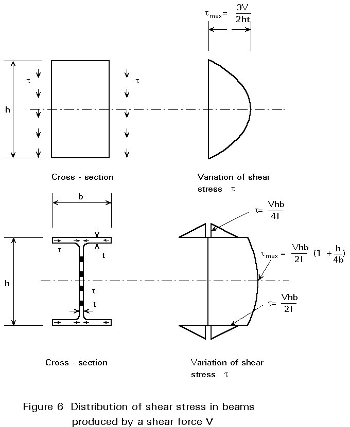
Figure 6 illustrates the pattern of shear stress found in a rectangular section and in an I-section assuming elastic behaviour. In both cases shear stress varies parabolically with depth, with the maximum value occurring at the neutral axis. However, for the I-section, the difference between maximum and minimum values for the web, which carries virtually the whole of the vertical shear force, is sufficiently small for design to be simplified by working with the average shear stress, i.e. total shear force/web area. Since the shear yield stress of steel is approximately 1/Ö3 of its tensile yield stress, a suitable value for "permissible" shear stress when using elastic design is 1/Ö3 of the permissible tensile stress.
The ultimate shear resistance (based on plastic principles) used in Eurocode 3 [1] is fyd/Ö3; this is used in conjunction with a shear area Av, examples of which are:
rolled I-section, load parallel to web Av = A-2btf + (tw+2r)tf
plates and solid bars Av = A
circular hollow sections Av = 2A/p
In cases where high shear and high moment coexist, e.g. the internal support of a continuous beam, it may sometimes be necessary to allow for interaction effects. However, since the full shear capacity may be developed in the presence of quite large moments and vice versa (Eurocode 3 only requires reductions in moment resistance when the applied shear exceeds 50% of the ultimate shear resistance [1]) this will not often be required.
Excessive deflections, whilst not normally leading to a structural failure, may, nonetheless, impair the serviceability of the structure.
Deflection might, for example, cause:
Since these affect the performance of the structure in its working conditions, it is usual to conduct this type of check at service load levels. Eurocode 3 suggests a limit of span/300 for the maximum deflection of beams supporting floors under service live load [1]. Such limits should, however, be regarded as advisory only, and smaller or larger values can be more appropriate in any given situation. Wherever possible, specialist advice should be sought; crane manufacturers, for example, should be able to give detailed guidelines regarding permissable deflection for gantry beams.
For sections with a single axis of symmetry bent about the perpendicular axis, the elastic distribution of bending stresses will be as shown in Figure 7. Due to its lack of symmetry about the neutral axis, the stress on the top and bottom flanges will not be equal; for example, the stress on the smaller flange, in the case of an unequal flanged I-beam, will exceed that on the bigger. Therefore, in elastic design, it is necessary to use the smaller of the two elastic section moduli Wmin.
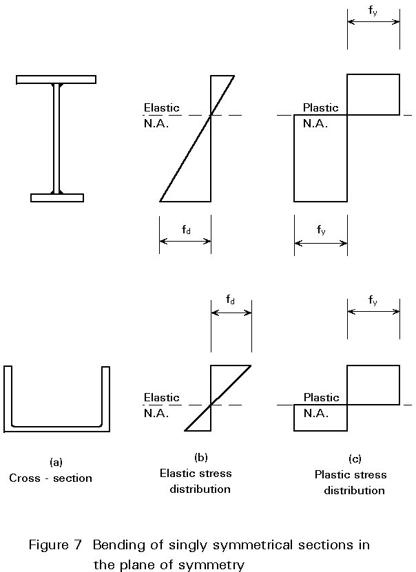
At full plasticity, the line of zero stress must be positioned so that it divides the area of the section into two equal parts, as shown in Figure 7c. Since the plastic section modulus Wpl is defined from Equation (3) as the ratio of Mpl/fy, there will be a single value for both faces of the section. Thus, when using ultimate moment resistance, the design condition will remain as Equation (4).
Doubly or singly-symmetrical sections subject to bending moments My, Mz about both principal axes may be treated as the sum of two uniaxial problems. Thus, in elastic design, it is necessary to satisfy the linear interaction equation:
![]() (6)
(6)
in which Wy and Wz are the elastic section moduli of the cross-section with respect to the axes y and z and
fd is the limiting normal bending stress.
This is based on the idea of limiting the maximum combined stress in the section to the design value. Care is necessary when dealing with sections such as angles for which the principal axes are not rectangular.
When using the plastic strength of the cross-section, analysis (which entails the location of the plastic neutral axis) shows that the shape of the interaction between moments will depend upon the geometry of the cross-section. Safe approximations to these interaction diagrams have therefore been provided in Eurocode 3 [1]. These adopt the form:
 (7)
(7)
in which Mply and Mplz are moment capacities about the y and z axis respectively and the values of a and b depend on the particular section under consideration; safe values are a = b = 1,0.
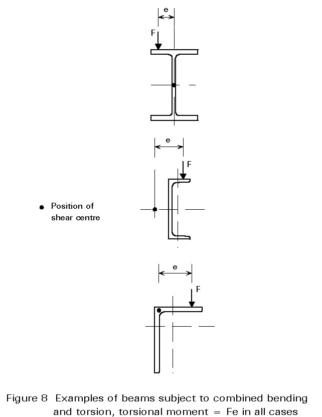
Loads which do not act through the shear centre of the section (see Figure 8) will also cause twisting (the shear centre coincides with the centroid for doubly-symmetrical sections, and lies on the axis of symmetry for singly-symmetrical sections.) This will induce shear stresses due to torsion and, in the case of open sections, may also produce significant additional longitudinal stresses due to the structural effect known as warping. Proper consideration of this complex topic requires an appreciation of the theory of torsion which is outside the scope of this lecture. In many cases torsional effects can be minimised by careful detailing such that load is transferred into members in a way that avoids twisting.
[1] Eurocode 3: " Design of Steel Structures": ENV 1993-1-1: Part 1.1: General rules and rules for buildings, CEN, 1992.
|
Beam Type |
Span Range (m) |
Notes |
|
0. Angles |
3 - 6 |
used for roof purlins, sheeting rails, etc., where only light loads have to be carried. |
|
1. Cold-formed sections |
4 - 8 |
used for roof purlins, sheeting rails, etc., where only light loads have to be carried. |
|
2. Rolled sections UB, IPE, UPN, HE |
1 - 30 |
most frequently used type of section; proportions selected to eliminate several possible types of failure. |
|
3. Open web joists |
4 - 40 |
prefabricated using angles or tubes as chords and round bar for web diagonals; used in place of rolled sections. |
|
4. Castellated beams |
6 - 60 |
used for long spans and/or light loads, depth of UB increased by 50%, web openings may be used for services, etc. |
|
5. Compound sections e.g. IPE+UPN |
5 - 15 |
used when a single rolled section would not provide sufficient capacity; often arranged to provide enhanced horizontal bending strength as well. |
|
6. Plate girders |
10 - 100 |
made by welding together 3 plates, sometimes automatically; web depths up to 3-4m sometimes need stiffening. |
|
7. Box girders |
15 - 200 |
fabricated from plate, usually stiffened; used for OHT cranes and bridges due to good torsional and transverse stiffness properties. |
TABLE 1