ESDEP WG 7
ELEMENTS
To present and discuss procedures for the design of restrained beams including consideration of moment redistribution for Class 1 sections [1].
Elastic theory for uniaxial and biaxial bending combined with shear forces.
Lectures 2.3: Engineering Properties of Steels
Lecture 7.2: Cross-Section Classification
Lectures 7.10: Beam Columns
Worked Example 7.8: Laterally Restrained Beams
The mechanism of redistribution of bending stress in a steel beam after the attainment of first yield is explained. For statically determinate beams, the idea of failure by the development of full plasticity at a cross-section is introduced, leading to the concepts of plastic section modulus and shape factor. Statically indeterminate beams are shown to be capable of developing several such regions - termed plastic hinges - before collapsing as a mechanism. The influence of shear forces is discussed from a design point of view, and behaviour in bending about both principal axes is briefly considered.
b width
e
straine
1 & e2 strains on extreme fibresd overall depth of section
Est strain hardening modulus
e
y yield strainf
curvatureF applied load
fd limiting stress in material
fly lower yield stress
fp limit of proportionality
fuy upper yield stress
fy material yield strength
L span
M moment
Mplr plastic moment resistance in presence of an axial load
Mplv plastic moment resistance in presence of shear load
My moment at first yield (fyW)
Npl squash load (fyA)
t
y yield shear stresss shape factor (Wpl/W)
fmax maximum stress on extreme fibre
tw web thickness
Vpw web shear resistance, at shear yield
Vs applied shear force
W elastic section modulus
Wpl plastic section modulus
s
normal stresst
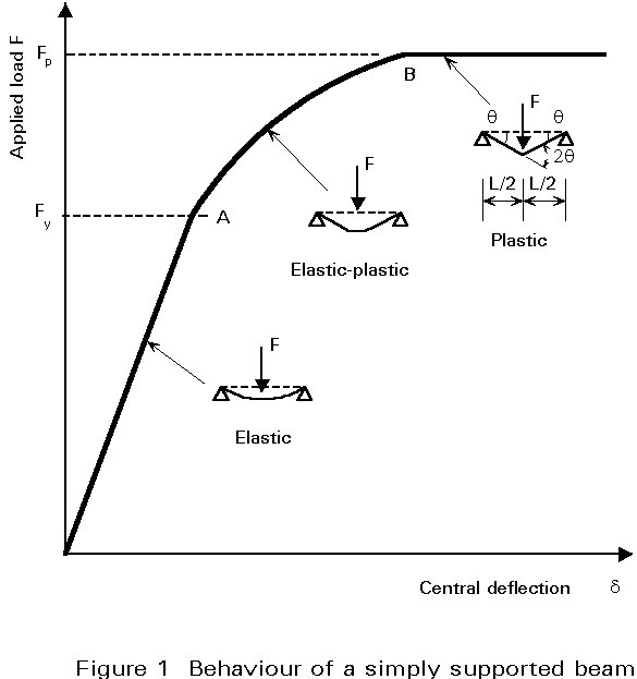
shear stressWhen a restrained steel beam of "compact" proportions (see Lecture 7.8.1) is subjected to loads producing vertical bending, its response will consist of a number of stages. Initially it will behave elastically, with vertical deflections being related linearly to the applied load. As the loading is increased, the most highly stressed regions will develop strains in excess of yield, resulting in a local loss of stiffness. For the beam as a whole, deflections will now start to increase rather more rapidly. Additional load will cause this process to continue until complete plasticity is reached at one cross-section. For a simply supported beam, this point will correspond to the maximum load that can be carried without strain hardening and will also be the point at which deflections become very large. On the other hand, for continuous structures, further increases of load are possible as redistribution of moments takes place.
It is the purpose of this lecture to discuss the concept of plasticity as it influences the design of beams, showing how the basic procedures of Lecture 7.8.1 may be modified to allow for this behaviour.
Figure 1 presents the relationship between applied load and central deflection that would be obtained from a test on a simply supported steel beam of Class 2 proportions or better. Three distinct phases may be identified:
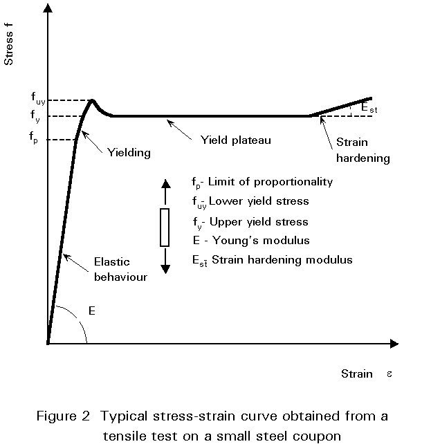
Because phases 2 and 3 involve the development of plasticity in regions of high stress, full understanding of the beam's response first requires that the behaviour of the material itself be considered.
Figure 2 presents a stress-strain curve of the type that would be obtained from a tensile test on a small piece of steel, called a 'coupon'. Rather than work directly with this, calculations may be considerably simplified if the idealised, bilinear response of Figure 3 is substituted. This comprises an initial elastic portion, followed by a horizontal, perfectly plastic portion. It therefore neglects such features as the upper yield point, strain hardening etc., the inclusion of which would have only a very small effect on the resulting analysis for a substantial increase in complexity.
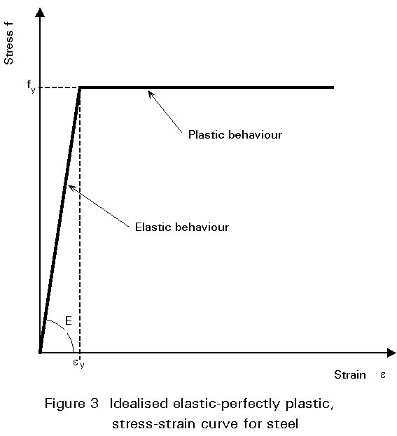
Using Figure 3, the relationship between moment (M) and curvature (f) for a cross-section can be derived by considering the distributions of strain and stress at various stages, shown in Figure 4. Providing the maximum strain at the extreme fibre (e1) remains below the yield strain (ey), then the corresponding stress distribution will be linear, as shown in Figure 4a.
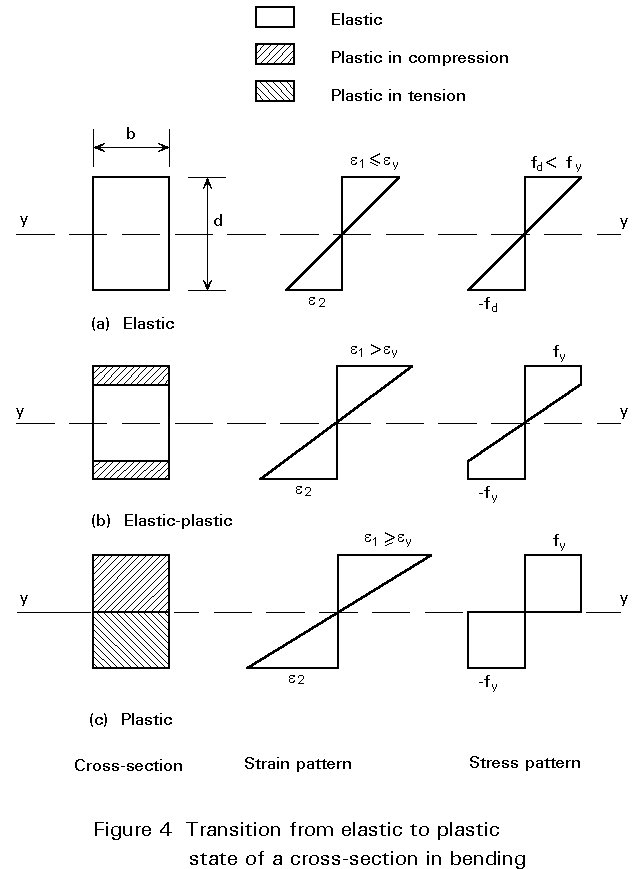
Assuming a beam of depth d, curvature will be given by:
f
= (e1 - e2)/ d (1)The corresponding moment of resistance may be determined by taking moments of the stress diagram about the neutral axis (yy). Assuming a rectangular section of width b gives:
M = s (bd2/6) (2)
in which (bd2/6) is termed the elastic section modulus (W).
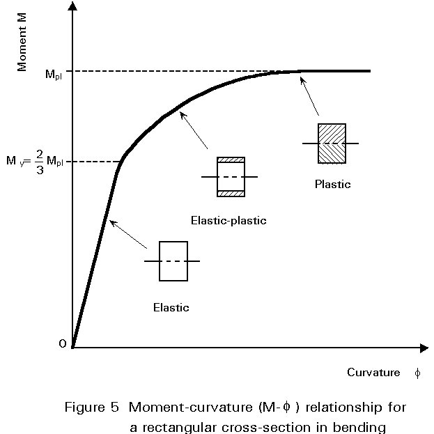
Once e1 exceeds ey, since s cannot exceed fy, the shape of the stress distribution will change, as shown in Figure 4b, with the result that f will now increase more rapidly, i.e. the M-f relationship will become non-linear, as shown in Figure 5. f may still be obtained from Equation (1) whilst M may be calculated as before, using Figure 4b.
Eventually the condition shown in Figure 4c will be approached (replacing the actual stress distribution with the two rectangular stress blocks is, of course, an approximation that greatly simplifies calculation for negligible loss in accuracy) for which M is given by:
M = fy (bd2/4) (3)
This is termed the fully plastic moment (Mpl) of the cross-section; it represents the theoretical upper limit on moment resistance based on the stress-strain behaviour of Figure 3. The quantity Wpl = bd2/4 is termed the plastic section modulus and the ratio Wpl/W, which is a measure of the additional moment that can be carried beyond the first yield, is the shape factor. For a rectangular section:
s = Wpl/W = (bd2/4)/bd2/6) (4)
Therefore s = 1,50
Values of W, Wpl and s for several structural shapes are given in Table 1.
Since the slope of the M-f curve decreases effectively to zero at Mpl, the cross-section is said to form a plastic hinge, because bending stiffness locally in this region will be zero, i.e. the beam now acts as if it contains a real hinge, with the difference that the moment at this hinge remains at Mpl. For a simply supported beam, the formation of a plastic hinge, rather than the attainment of first yield, provides a close estimate of its maximum load carrying resistance. A simple method of determining the load at which this occurs, consists of treating the elastic portions of the beam as rigid and equating the work done by the external loads to the energy dissipated by the plastic hinge. For the example of Figure 1 this gives:
FLq/2 = Mpl.2q (5)
F = 4Mpl/L
This approach uses the concept of the structure being transformed into a mechanism at collapse.
If the steel beam is continuous and Class 1, then the formation of the first plastic hinge at the point of maximum moment, previously obtained from an elastic analysis, will not mark the limit of its load-carrying resistance (see Figure 6). Rather, it signifies a change in the way in which the beam responds to further loads. For the two-span beam of Figure 6 the insertion of a real hinge at the central support (B) would cause each span to behave as if it were simply supported. Thus both would be capable of sustaining load, and would not collapse until this load caused a plastic hinge to form at mid-span. The formation of a plastic hinge at B produces qualitatively similar behaviour. Thus continuous structures do not collapse until sufficient plastic hinges have formed to convert them into a mechanism. At collapse, the beam will appear as shown in Figure 6.
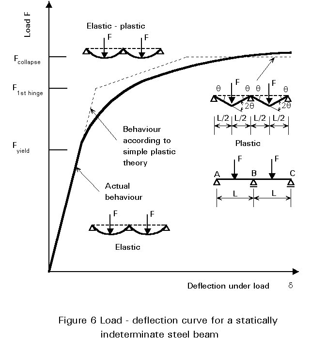
Equating external and internal work as before for this collapse mechanism gives:
2FLq/2 = Mpl (2q + 2q + 2q) (6)
F = 6Mpl/L
Figure 6 shows the load-deflection curve for this two-span beam obtained from an elastic-plastic analysis. Each change in slope corresponds to the formation of a plastic hinge which produces progressive "softening" of the structure. Collapse occurs at an applied load given by Equation (6) when sufficient hinges have formed to transform the beam into a mechanism with no inherent stiffness, corresponding to the final horizontal segment of the curve. It is usual, when conducting this type of analysis, to assume that plastic hinges form suddenly; this corresponds to regarding the cross-section as having a unit shape factor, i.e. Wpl = W. Comparing the resulting load-deflection curve with the more rounded curve obtained from an actual test shows how neglecting the spread of plasticity has comparatively little effect on the overall behaviour.
Although the elastic-plastic analysis of statically indeterminate beams is quite complex, the determination of the collapse load from considerations of the collapse mechanism for most types of continuous beam is relatively straightforward. A similar approach is also possible for plastically designed, portal frame structures.
It should be noted that, in passing from the elastic state corresponding to loads up to Fyield to the plastic state corresponding to the load Fcollapse, the beam of Figure 6 has undergone a redistribution of moment. Thus the shape of the plastic moment diagram will differ from that of the elastic moment diagram. In this case the former will correspond to Mpl at all three plastic hinges, whilst the latter will have a maximum at the central support.
Applying the stress-strain curve of Figure 3 to the idealised I-section of Figure 7a bending about the yy axis, in which half of the area is assumed to be concentrated at the mid-depth of each flange, leads to the bilinear M-f curve of Figure 8. Thus, for this hypothetical cross-section, full plasticity and first yield coincide and the shape factor is unity.
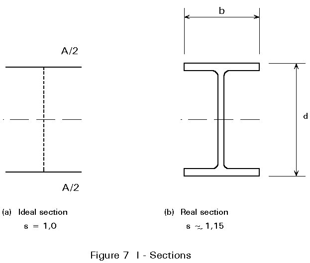
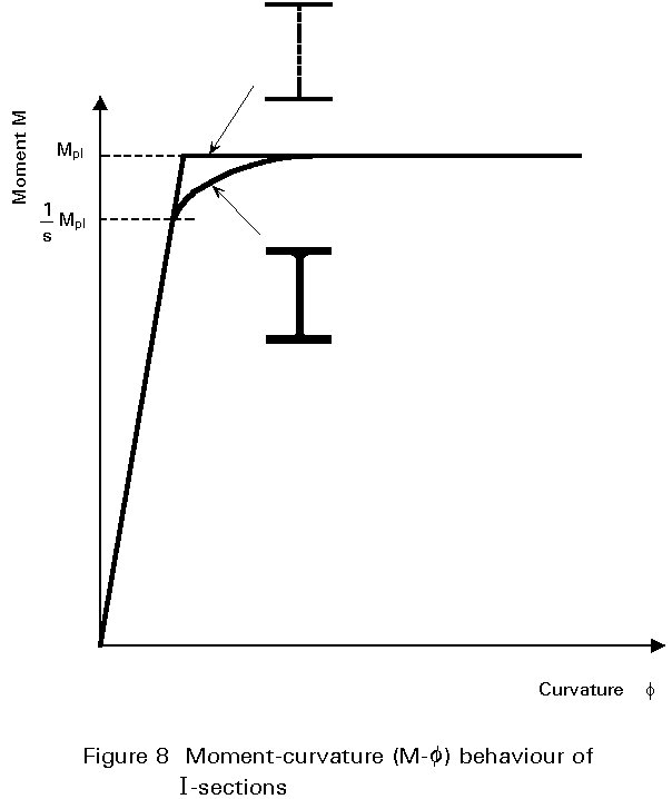
Taking the more realistically proportioned beam with shape as shown in Figure 7b, produces an M-f curve with a rounded 'knee' as indicated in Figure 8. Since this 'knee' corresponds to the spread of plasticity, it starts at a moment equal to Mpl/s. A typical value of s for an I-beam section would be 1,15 for strong axis bending. For weak axis bending of I-sections s » 1,5.
An elastic-plastic analysis for any cross-sectional shape, bent about its axis of symmetry, may be performed using the approach described previously for a rectangular section. If necessary a more precise representation of the material stress-strain curve may be employed but this does, of course, complicate the arithmetic.
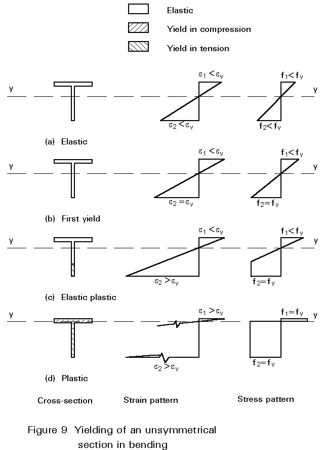
An elastic-plastic analysis for a cross-section that is not bent about an axis of symmetry, is complicated by the shift in the position of the neutral axis that occurs as plasticity develops. Initially the elastic neutral axis will pass through the centroid as shown in Figure 9a. However, because of the unequal strains on the top and bottom surfaces of the section, yield will occur first at one edge only as shown in Figure 9b. Plasticity will thus spread inwards in an unsymmetrical fashion as shown by Figure 9c. Equilibrium of axial forces at all such intermediate stages requires a balance of compressive and tensile forces. For this requirement to be met, the line of zero stress must move away from the yielded material as the force in this part of the cross-section will be increasing less rapidly. Eventually, upon attaining full plasticity as shown in Figure 9d, the section's neutral axis must coincide with the equal area axis, i.e. the line dividing the section into two halves. Calculation of Mpl for an unsymmetrical section therefore requires a knowledge of the location of the equal area axis, rather than the use of the centroidal axis used when dealing with elastic behaviour.
Singly-symmetrical sections have two different values of the elastic section modulus for the two faces, because of the different distances of the latter from the elastic neutral axis. However, such sections possess a single value of plastic section modulus equal to Mpl/fy. They will therefore have two values of shape factor depending on which of the faces is under consideration. For extreme sections such as tees, these may differ quite widely with one value actually being less than unity. Although this does not, of course, affect the basic relationship between My and Mpl for the section, it can be a source of confusion in situations which require the specific consideration of yield in compression (or tension).
Consideration of the effect of shear on plastic moment resistance first requires an assumption about the way in which steel yields under the action of direct and shear stress. This is represented by:
(s/fy)2 + (t/ty)2 = 1 (7)
in which ty = yield shear strength (taken as fy/Ö3 according to the Von Mises criterion) and rounded to 0,6fy.
Applying this to assumed plastic patterns of bending and shear stress for a rectangular section, leads to the following approximate relationship between the applied shear force (Vs), reduced plastic moment resistance (Mplv), the shear force required for yield in shear (Vpw), and Mpl :
Mplv = ![]() for
for ![]() (8)
(8)
Applying Equation (7) to a fully plastic I section (see Figure 10), assuming that the shear stresses in the web are uniform and that Vpw = 0,6dtwfy (ty = 0,6 fy), gives:
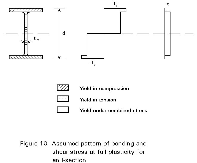
Mplv = ![]() for 0,5Vpw £ Vs £ Vpw (9)
for 0,5Vpw £ Vs £ Vpw (9)
Mplv = Mpl for Vs £ 0,5Vpw
Thus for I-sections bent in the plane of the web, shear forces of less than 50% of the plastic resistance of the web in shear have no significant effect on Mpl. For bending about the minor axis, behaviour is similar to that of a rectangular section, as described by Equation (8).
Analyses for cross-sectional resistance under combinations of moment and shear have been performed for various structural shapes using a number of variants of plasticity theory. For design purposes, results are normally expressed either graphically or as approximate interaction formulae. In the case of an I-section bent about its major axis, no reduction in Mpl for shears of less than one half of Vpw is necessary.
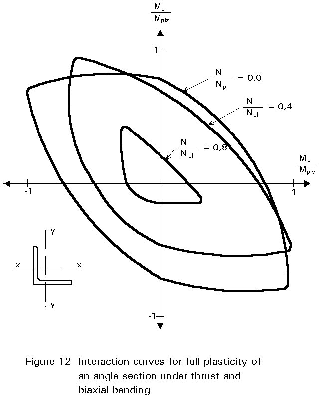
When bending takes place about both axes of the cross-section, the plastic neutral axis will be inclined to the rectangular axes by an amount which depends on the ratio of the applied moments and the exact shape of the section. By assuming stress distributions and calculating corresponding moments of resistance, a relationship between the two reduced plastic moment resistances (Mplry and Mplrz) and the basic plastic moment resistances (Mply and Mplz) may be obtained. If required, such calculations may also include the effects of axial load (N). Although tedious, these have been performed for a variety of structural shapes (see Figures 11 and 12), including unsymmetrical sections such as angles. For an I or H shape under biaxial bending, a suitable expression relating Mplry and Mplrz is:
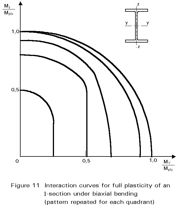
![]() (10)
(10)
Providing the section has at least one axis of symmetry and the problem is worked in terms of its principal axes, it is always safe to use the linear equivalent of Equation (10), viz:
![]() (11)
(11)
[1] Eurocode 3: "Design of Steel Structures": ENV 1993-1-1: Part 1.1: General rules and rules for buildings, CEN, 1992.
|
Section |
Elastic section modulus W |
Plastic section modulus Wpl |
Shape factor s |
|
Rectangle |
bd2/6 |
bd2/4 |
1,5 |
|
I: major axis |
[bd3-(b-tw)h3]/6d |
btf(d-tf) + tw(d-2tf)2/4 |
approx. 1,15 |
|
I: minor axis |
|
b2tf/2 + (d-2tf)tw2/4 |
approx. 1,67 |
|
Solid circular |
p d3/32 |
d3/6 |
1,7 |
|
Circular hollow section |
p [d4-(d-2t)4]/32d |
If t << d; td2 |
for t = d/10; 1,4 for t << d; 1,27 |
|
Channel |
[bd3-(b-tw)h3]/bd |
btf(d-tf) + tw(d-2tf)2/4 |
approx. 1,15 |
Table 1 Values of W, Wpl and s for various shapes