
ESDEP WG 7
ELEMENTS
To describe the classification of cross-sections and explain how this controls the application of the methods of analysis given in Eurocode 3 [1].
Lecture 7.1: Methods of Analysis of Steel Structures
Lecture 7.3: Local Buckling
Lectures 7.5.1 & Lecture 7.5.2: Columns
Lectures 7.8: Restrained Beams
Lectures 7.9: Unrestrained Beams
Lectures 7.10: Beam Columns
Lecture 7.11: Frames
Lecture 14.10: Simple Braced Non-Sway Multi-Storey Buildings
Worked Example 7.1: Cross-Section Classification
The analysis methods used are primarily dependent upon the geometry of the cross-section and especially on the width-thickness ratio of the elements which make it up.
The lecture describes how sections are classified as plastic, compact or semi-compact and gives the limiting proportions of the elements by which these classifications are made.
When designing a structure and its components, the designer must decide on an appropriate structural model. The choice of model effects:
Thus a model implies the use of a method of analysis combined with a method of cross-section resistance calculation.
There are several possible combinations of methods of analysis and methods of cross-section calculation, for the ultimate limit state, involving either an elastic or plastic design approach; the possible combinations are listed in Table 1.
Table 1 Ultimate Limit State Design - Definition of Design Models
|
Model |
Method of Global Analysis (Calculation of internal forces and moments) |
Calculation of Member Cross-Section Resistance |
|
I II III IV |
Plastic Elastic Elastic Elastic |
Plastic Plastic Elastic Elastic Plate Buckling |
Model I is related to plastic design of structures. Full plasticity may be developed within cross-sections, i.e. the stress distribution corresponds to a fully rectangular block, so that plastic hinges can form. These have suitable moment rotation characteristics giving sufficient rotation capacity for the formation of a plastic mechanism, as the result of moment redistribution in the structure.
For a structure composed of sections which can achieve their plastic resistance, but have not sufficient rotation capacity to allow for a plastic mechanism in the structure, the ultimate limit state must refer to the onset of the first plastic hinge. Thus, in Model II, the internal forces are determined using an elastic analysis and are compared to the plastic capacities of the corresponding cross-sections. For statically determinate systems, the onset of the first plastic hinge produces a plastic mechanism; both methods I and II should thus give the same result. For statically indeterminate structures, Model II, in contrast to Model I, does not allow moment redistribution.
When the cross-sections of a structure cannot achieve their plastic capacity, both analysis and verification of cross-sections must be conducted elastically. The ultimate limit state, according to Model III, is achieved when yielding occurs at the most stressed fibre. Sometimes yielding in the extreme fibre cannot even be attained because of premature plate buckling of one component of the cross-section; in such cases, the above ultimate limit state should apply only to effective cross-sections (Model IV).
It is obviously not possible to have a model where a plastic method of analysis is combined with an elastic cross-section verification. Indeed, the moment redistribution which is required by the plastic analysis cannot take place without some cross-sections being fully yielded.
In the previous section, the models are defined in terms of structural design criteria; these are actually governed by conditions related to stability problems. Plastic redistribution between cross-sections and/or within cross-sections can take place provided that no premature local buckling occurs, as this would cause a drop-off in load carrying capacity.
It must be guaranteed that no local instability can occur before either the elastic (Model III), or the plastic (Model II), bending resistance of the cross-section, or the formation of a complete plastic mechanism (Model I), is achieved.
Such a mechanism, as envisaged by Model I, can occur provided that the plastic hinge, once formed, has the rotational capacity required for the formation of a plastic mechanism.
To ensure sufficient rotation capacity, the extreme fibres must be able to sustain very large strains without any drop-off in resistance. In tension, the usual steel grades have sufficient ductility to allow for the desired amount of tensile strains; in addition, no drop-off is to be feared before the ultimate tensile strength is reached. With compressive stresses, however, it is not so much a question of material ductility, as of ability to sustain these stresses without instability occurring.
Table 2 gives a summary of the requirements for cross-sections in terms of behaviour, moment capacity and rotational capacity. As can be seen from this table, the limits are referred to cross-section classes, according to Eurocode 3 [1], each corresponding to a different performance requirement:
Class 1 Plastic cross-sections: those which can develop a plastic hinge with sufficient rotation capacity to allow redistribution of bending moments in the structure.
Class 2 Compact cross-sections: those which can develop the plastic moment resistance of the section but where local buckling prevents rotation at constant moment in the structure.
Class 3 Semi-compact cross-sections: those in which the stress in the extreme fibres should be limited to yield because local buckling would prevent development of the plastic moment resistance of the section.
Class 4 Slender cross-sections: those in which yield in the extreme fibres cannot be attained because of premature local buckling.
Table 2 Cross-section requirements and classification
The moment resistances for the four classes defined above are:
for Classes 1 and 2: the plastic moment (Mpl = Wpl . fy)
for Class 3: the elastic moment (Mel = Wel . fy)
for Class 4: the local buckling moment (Mo < Mel).
The response of the different classes of cross-sections, when subject to bending, is usefully represented by dimensionless moment-rotation curves.
The four classes given above are recognised for beam sections in bending. For struts loaded in axial compression, Classes 1, 2 and 3 become one, and, in the absence of overall buckling are referred to as "compact"; in this case Class 4 is referred to as "slender".
The classification of a specific cross-section depends on the width-to-thickness ratio, b/t, of each of its compression elements. Compression elements include any component plate which is either totally or partially in compression, due to axial force and/or bending moment resulting from the load combination considered; the class to which a specified cross-section belongs, therefore, partly depends on the type of loading this section is experiencing.
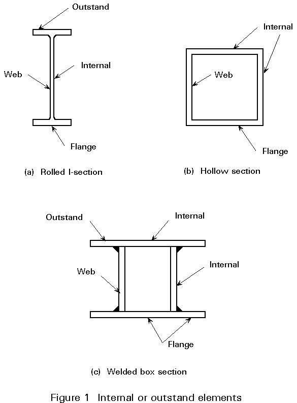
a. Components of cross-section
A cross-section is composed of different plate elements, such as web and flanges; most of these elements, if in compression, can be separated into two categories:
These cases correspond respectively to the webs of I-sections (or the webs and flanges of box sections) and to flange outstands (Figure 1).
b. Behaviour of plate elements in compression
For a plate element with an aspect ratio, a = a/b (length-to-width), greater than about 0,8, the elastic critical buckling stress (Euler buckling stress) is given by:
s
cr = kswhere ks is the plate buckling factor (see below),
u Poisson's coefficient,
E Young's modulus.
The critical buckling stress is proportional to (t/b)2 and, therefore, is inversely proportional to (b/t)2. The plate slenderness, or width-to-thickness ratio (b/t), thus plays a similar role to the slenderness ratio (L/i) for column buckling.
In accordance with the definition of Class 3 sections, the proportions of the plate element, represented by the b/t ratio, must be such that scr would exceed the material yield strength fy so that yielding occurs before the plate element buckles. The ideal elastic-plastic behaviour of a perfect plate element subject to uniform compression may be represented by a normalised load-slenderness diagram, where the normalised ultimate load:
![]() = su/fy
= su/fy
and the normalised plate slenderness:
![]() p
=
p
= ![]()
are plotted as ordinates and abscissae respectively (Figure 2).
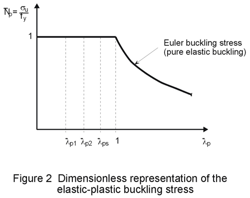
For ![]() p
< 1,
p
< 1,
![]() = 1 which means that the plate element can develop its squash load su = fy. For
= 1 which means that the plate element can develop its squash load su = fy. For
![]() p > 1,
p > 1,
![]() decreases as the plate slenderness increases, su being equal to scr. Substituting the Equation (1) value for scr into the above and taking u = 0,3 gives:
decreases as the plate slenderness increases, su being equal to scr. Substituting the Equation (1) value for scr into the above and taking u = 0,3 gives:
![]() p =
p =  (2)
(2)
This expression is quite general as loading, boundary conditions and aspect ratio all influence the value of the buckling factor ks .
The factor ks is a dimensional elastic buckling coefficient, depending on edge support conditions, on type of stress and on the ratio of length to width (a/b), aspect ratio, of the plated element.
In general, the plated elements of a section have an aspect ratio much larger than unity and most of them are submitted to uniform compression. For such cases, Table 3 gives buckling factors for plated elements having various long edge conditions.
Table 3 Elastic buckling factor ks

When plated elements of sections are submitted to any kind of direct stress, other than uniform compression (e.g. webs of a girder in bending), the buckling factor ks has to be modified to take account of the stress gradient, given by the stress ratio, y.
Table 4 gives the buckling factors for different stress ratios y , for internal or outstand elements. In the latter case a distinction is made for elements with tip in compression or in tension.
Table 4 Buckling factors and stress distribution

c. Limit plate element slendernesses
The actual behaviour is somewhat different from the ideal elastic-plastic behaviour represented in Figure 2 because of:
i. initial geometrical and material imperfections,
ii. strain-hardening of the material,
iii. the postbuckling behaviour.
Initial imperfections result in premature plate buckling, which occurs for ![]() p
< 1. The corresponding limit plate slenderness
p
< 1. The corresponding limit plate slenderness ![]() p3, for Class 3 sections, may differ substantially from country to country because of statistical variations in imperfections and in material properties which are not sufficiently well known to be quantified accurately; a review of the main national codes shows that it varies from 0,5 to 0,9 approximately. Eurocode 3 [1,2] has adopted
p3, for Class 3 sections, may differ substantially from country to country because of statistical variations in imperfections and in material properties which are not sufficiently well known to be quantified accurately; a review of the main national codes shows that it varies from 0,5 to 0,9 approximately. Eurocode 3 [1,2] has adopted
![]() p3
= 0,74 as the limit plate slenderness of Class 3 compression elements and
p3
= 0,74 as the limit plate slenderness of Class 3 compression elements and ![]() p3
= 0,9 for elements in bending where the yield strength may be reached in the extreme fibre of the cross-section. For plate elements for which
p3
= 0,9 for elements in bending where the yield strength may be reached in the extreme fibre of the cross-section. For plate elements for which
![]() p <
p <
![]() p3, no plate buckling can occur before the maximum compressive strength reaches the yield strength.
p3, no plate buckling can occur before the maximum compressive strength reaches the yield strength.
A Class 1 section must develop a resistance moment equal to the plastic capacity of the section and must maintain this resistance through relatively large inelastic deformations. In order to fulfil these conditions without buckling, the entire plate element must be yielded and the material must be strained in the strain-hardening region (see Table 2); this is only possible for elements with low reference slendernesses (![]() p
<
p
< ![]() p1), see Figure 2.
p1), see Figure 2.
On the basis of certain theoretical approaches [3, 4, 5] values of ![]() p1
between 0,46 and 0,6, are proposed in various standards. The difference can be explained in the choice of the amount of necessary rotation capacity. A value of
p1
between 0,46 and 0,6, are proposed in various standards. The difference can be explained in the choice of the amount of necessary rotation capacity. A value of
![]() p1
= 0,6 corresponds to a limited rotation capacity which is estimated to be sufficient for usual plastic design (continuous beams, non-sway frames, etc.). In Eurocode 3 [1], the proposed value is:
p1
= 0,6 corresponds to a limited rotation capacity which is estimated to be sufficient for usual plastic design (continuous beams, non-sway frames, etc.). In Eurocode 3 [1], the proposed value is:
![]() p1
= 0,5
p1
= 0,5
A Class 2 (or compact section) is one which can just reach its plastic moment resistance but has a rapid drop-off in resistances at that point (Table 2). The plate element is yielded and the material strained in the plastic range; it occurs for elements with medium reference slendernesses
![]() p2 where:
p2 where:
![]() p1
<
p1
< ![]() p2
<
p2
< ![]() p3
p3
In Eurocode 3 [1], the proposed value is ![]() p1
= 0,6.
p1
= 0,6.
Using formula (2), and the appropriate values of ![]() p
and ks , the limiting b/t ratios can be calculated. Table 5 gives some limiting value of b/t for the elements of the cross-section of a rolled I-profile in compression or bending.
p
and ks , the limiting b/t ratios can be calculated. Table 5 gives some limiting value of b/t for the elements of the cross-section of a rolled I-profile in compression or bending.
Table 5 Maximum slenderness ratios for the elements of a rolled section in compression or in bending
|
Element |
Class 1 cross- section |
Class 2 cross- section |
Class 3 cross-section |
|||||||
| Formula | ks | b*/t or d/tw | ||||||||
|
Flange (1) (b*/t) |
9e |
10e |
21e |
0,43 |
14e (1) |
|||||
|
Web in compression d/tw |
33e |
38e |
21 |
1,0 |
42e |
|||||
|
Web in pure bending d/tw |
72e |
83e |
25,4e |
23,9 |
124e |
|||||
|
fy |
235 |
275 |
355 |
|||||||
|
e = |
e |
1,0 |
0,92 |
0,81 |
||||||
|
(1) In practice, b, the half-width of the flange is considered instead of b*. For this reason, the values given in the "Essentials of Eurocode 3" is b = 15 e > b*. |
||||||||||
The most important limiting proportions of the elements of a cross-section, which enable the appropriate classifications to be made, are specified in Eurocode 3 [1]. Appendix 1 gives the limiting proportions for compression elements of Class 1 to 3.
The limiting values of the width-to-thickness ratio (b/t) of the plate elements of sections apply to members in steel of a specific yield strength. In order to cover all grades of steel, Eurocode 3 presents local buckling data non-dimensionally, in terms of a reduction factor e = ![]() , where 235 represents the yield stress of mild steel and fy that of the steel considered.
, where 235 represents the yield stress of mild steel and fy that of the steel considered.
The various compression elements in a cross-section (such as a web or a flange) can, in general, be in different classes and a cross-section is normally classified by quoting the least favourable (highest) class of its compression elements.
It is important, particularly in plastic design, that the sections selected for various members should be, in all cases, appropriate for the assumed mode of behaviour.
When any of the compression elements of a cross-section fail to satisfy the limits given in Table 5 for Class 3, the section is classified as "slender" and local buckling shall be taken into account in the design. This may be done by means of the effective cross-section method which is discussed in detail in Lecture 7.3.
[1] Eurocode 3: "Design of Steel Structures": ENV 1993-1-1: Part 1.1: General rules and rules for buildings, CEN, 1992.
[2] Bureau, A. et Galea, Y., "Application de l'Eurocode 3: Classement des sections transversales en I".
Construction métallique, no. 1, 1991.
[3] Salmon, C.G., Johnson, J.E., "Steel Structures. Design and Behaviour", Harper et Row, Publishers, New York.
[4] Dubas, P., Gehri, E., "Behaviour and Design of Steel Plated Structures", Publication no. 44, ECCS, TC8, 1986.
[5] Commentaire de la norme SIA161 "Constructions Métalliques", Publication A5, Centre Suisse de la Construction Métallique, Zurich, 1979.
Chatto and Windus, London 1970.
APPENDIX I
Table 1 Maximum width-to-thickness ratios for compression elements
Table 2 Maximum width-to-thickness ratios for compression elements
Table 3 Maximum width-to-thickness ratios for compression elements
Table 4 Maximum width-to-thickness ratios for compression elements


