ESDEP WG 7
ELEMENTS
To introduce methods of global analysis and to relate them to the assumptions made on the material behaviour and on the effects of deformations.
Elementary mechanics of materials.
Elementary structural analysis.
Elements of plastic design.
Elastic and elastic-plastic behaviour of materials.
Lecture 7.2: Cross-Section Classification
Lecture 7.8.1: Restrained Beams I
Lecture 7.11: Frames
Lectures 14: Structural Systems: Buildings
Internal force distributions in structures may be determined using an elastic or a plastic global analysis. Either a first or second-order theory can be used, depending on the type of structure. These concepts are briefly reviewed and comments are made in general terms regarding design practice.
Checking the strength of cross-sections, the stability of structural members or section components and possibly fatigue requires that the internal force distribution within the structure, is known beforehand; from this, the stress distribution within any cross-section may be deduced as required. The words "internal forces" (also termed "member forces") are used generally and refer to axial forces, shear forces, bending moments, torque moments etc.
The internal forces in a statically determinate structure can be obtained using statics only. In a statically indeterminate structure, they cannot be found from the equations of static equilibrium alone; a knowledge of some geometric conditions under load is additionally required. It is important, at this stage, to recognise this fundamental difference between statically determinate and indeterminate (hyperstatic) structures. The internal forces in a structure may be determined using either an elastic or a plastic global analysis. While elastic global analysis may be used in all cases, plastic global analysis can be used only where both the member cross-sections and the steel material satisfy special requirements.
The internal forces may be determined using different approaches depending on whether the effects of the deformations in the structure can or cannot be disregarded. In first order theory, the computations are carried out by referring only to the initial geometry of the structure; in this case the deformations are so small that the resulting displacements do not significantly affect the geometry of the structure and hence do not significantly change the forces in the members. Second order theory takes into account the influence of the deformation of the structure and, therefore, reference must be made to the deflected geometry under load. First order theory may, for instance, be used for the global analysis in cases where the structure is appropriately braced, is prevented from sway, or when the design methods make indirect allowances for second-order effects. Second order theory may be used for the global analysis in all cases, without any restrictions.
When first order theory can be used, the behaviour of a structure made with a material obeying Hooke's law is itself linear; the displacements - translation or rotation of any section - vary linearly with the applied forces; that is, any increment in displacement is proportional to the force causing it. Under such conditions, stresses, strains, member forces and displacements due to different actions can be added using the principle of superposition. This principle indeed states that the displacements (internal forces) due to a number of loads acting simultaneously is equal to the sum of the displacements (internal forces) due to each load acting separately. This does not apply if the stress-strain relationship of the material is nonlinear or if the structure (even if it is made of a material obeying Hooke's law) behaves non-linearly because of changes in the geometry caused by the applied loads.
The principle of superposition, when it can be used, is especially useful when determining the most severe condition in each individual member of a statically indeterminate structure; the interaction between different parts of the structure makes it difficult to identify the exact loading which produces the critical condition for design.
In practice, elastic global analysis is generally used to study the serviceability performance of a structure, i.e. limit states beyond which specified service criteria are no longer met. Plastic global analysis is particularly useful when investigating states associated with an actual collapse of the structure and to assess the actual ultimate resistance, i.e. ultimate limit states.
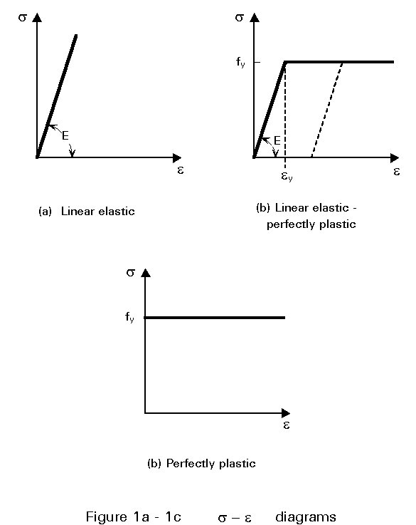
Elastic global analysis presumes elastic behaviour of the structure, and consequently, of the material itself. It is based on the assumption that the load-deformation behaviour of the material is linear, whatever the stress level; the strain is thus assumed proportional to the stress, i.e. the material is obeying Hooke's law in the whole range of loading (Figure 1a). Obviously, actual properties of the material, especially regarding yield stress and possibly strength, shall be considered when checking whether the member forces do or do not exceed the strength resistance of cross-sections and members.
It has already been stated that in the elastic global analysis of statically determinate structures, the internal forces are found from the equations of static equilibrium alone. In continuous construction (statically indeterminate structures) the member forces must satisfy the conditions of equilibrium and produce deformations compatible with the elastic continuity of the structure and with the support conditions. The equilibrium equations are not sufficient to determine the unknown forces and have to be supplemented by simple geometrical relationships between the deformations of the structure. These relationships are termed compatibility conditions because they ensure the compatibility of the deformations in the geometry of the deformed structure.
It is also required that the types of joints employed are able to maintain, virtually unchanged, the original angles between adjacent members, i.e. rigid connections are assumed.
Where first order theory can be used, equilibrium and compatibility conditions are expressed with reference to the initial (non deflected) configuration of the structure.
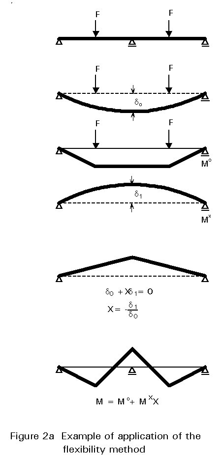
Two general methods of approach can be used to determine the force resultants and reaction components. The first of these is the flexibility method, in which releases are provided to render the structure statically determinate; the unknowns are the forces. These are determined by saying that the released structure undergoes inconsistent deformations, which are corrected by the application of appropriate additional forces (Figure 2a).
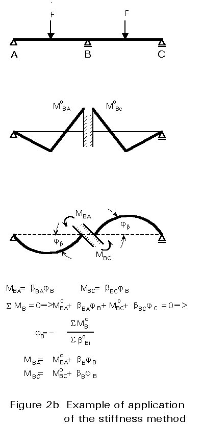
The second approach is the stiffness method, in which displacement restraints are added to prevent movement of the joints, and the forces required to produce the restraint are determined; the displacements are then allowed to take place at the joints until the fictitious restraining forces have vanished. Once the joint displacements are known, the forces in the structure are obtained by superposition of the effects of the separate displacements (Figure 2b).
Either the force or the displacement method can be used to analyse any structure. In the force method, the solution is carried out for the forces necessary to restore consistency in geometry; the analysis involves the solution of a number of simultaneous equations equal to the number of unknown forces, that is the number of releases required to render the structure statically determinate. In the displacement method, the unknowns are the possible joint displacements and rotations. The number of the restraining forces to be added to the structure equals the number of possible joint displacements and the analysis similarly involves the solution of a set of equations.
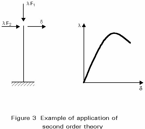
When it is necessary to account for second order effects (geometric non-linearity), second order theory must be used which involves iterative procedures. Because the principle of superposition is not allowed in this case, reference must be made to a specified reference load distribution. This is increased, in steps using a load multiplier (Figure 3). Each step is chosen sufficiently small so that the behaviour may be assumed linear during this load increment. The deflected configuration reached at the end of a specified loading step is used as the reference geometry for the following step; elastic second order theory thus consists in solving a succession of first order analyses of a structure, the geometry of which is changed at each step on the basis of its former history. Such computations become rapidly unmanageable by hand and appropriate computer programs are needed. These are usually based on the stiffness method - also termed displacement method - because it is easier to define the kinematically determinate structure, which is used as the reference geometry.
Most codes and standards permit member forces, in regular geometric non-linear structures, to be obtained using linear elastic analysis and then amplified, where necessary, to allow for instability effects. Because the principle of superposition is not applicable, this approach would appear to be inconsistent with rigorous theory. Nonetheless, it gives the designer the opportunity to use standard, i.e. linear elastic, frame analysis programs for a wide range of structures, at least for preliminary design.
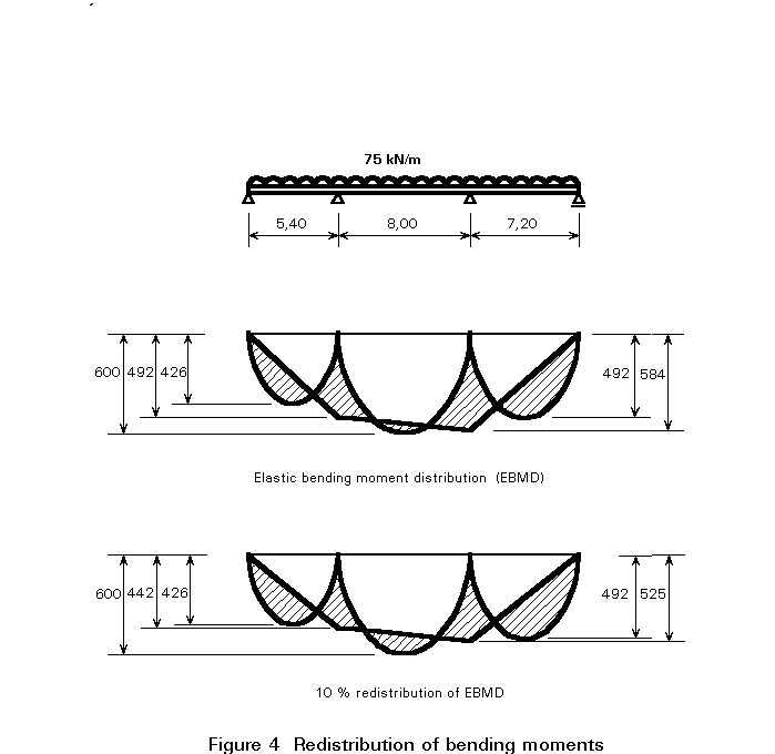
In certain circumstances, codes and standards permit a limited redistribution of moments. That means that the elastic moment diagram may be modified by up to 5 to 15% of the peak elastic moment, provided that the resulting computed moments and shears remain in equilibrium with the applied external loads (Figure 4). Therefore, although equilibrium is indeed maintained, the elastic compatibility of the structure is somewhat violated. This concept of moment redistribution may be thought of as a very limited recognition of the potential which exists, within statically indeterminate structures, to withstand loads in excess of those that require full elastic member bending strength only at the most critical location. Attention is drawn on the fact that this is possible only if unloading does not follow the attainment of the local maximum strength; some ductility of the cross-sectional behaviour is, therefore, required, which explains the reason for limiting the process to compact sections (see Lecture 7.2).
It should be stressed that the assumption of linear load-deformation behaviour of the material may be maintained for both first order and second order elastic analysis, even where the resistance of a cross-section is based on the plastic resistance (see Lecture 7.2).
The load-deformation behaviour of steel is not infinitely linear. The strain-stress relationship for an ideal elastic-perfectly plastic material is represented in Figure 1b; it follows that Hooke's law is restricted to a stress range s £ fy, fy being the yield stress of the material. Beyond this range, the material yields plastically at constant stress s = fy. If the stress is reduced at any point in the plastic range, the return path is a straight line parallel to Hooke's law, the slope of which is the elastic modulus E. Both E and fy, and indeed the whole stress-strain relationship are assumed the same for tension and for compression.
The idealised stress-strain relationship, although only a mathematical model, is a close approximation of the behaviour of structural mild steel as well as a reasonable first approximation to many continuously strain-hardening materials used in structural engineering. The assumption of perfect plasticity, after the yield stress is reached, amounts to ignoring the effects of strain hardening and is on the safe side.
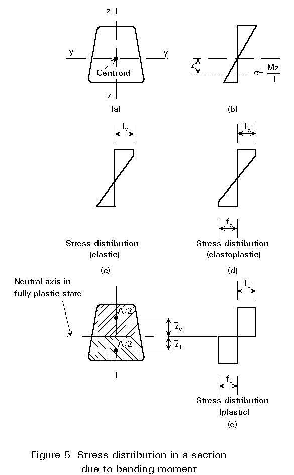
Consider a cross-section of area A, having an axis of symmetry and experiencing bending in the plane of symmetry (Figure 5). If the bending moment is small, the stress and the strain vary linearly across the depth. When the moment is increased, yield stress is first attained in one of the top fibres, and with a further increase the yield stress is reached in the bottom fibre as well. If the bending moment continues to increase, yield will spread from the outer fibres inward until the two zones of yield meet; the cross-section in this state is said to be fully plastic. The value of the ultimate moment, termed plastic moment, is deduced from equilibrium conditions. Since there is no axial force, the neutral axis of the fully yielded cross-section divides the latter into two equal areas A/2; the resultant tension and compression are each equal and form a couple equal to the ultimate moment:
Mpl = 0,5 A fy (![]() ) (1)
) (1)
where ![]() and
and ![]() are respectively the distance of the centroid of the compression and tension area from the neutral axis, in the fully plastic condition. For a doubly symmetrical cross-section, the distances
are respectively the distance of the centroid of the compression and tension area from the neutral axis, in the fully plastic condition. For a doubly symmetrical cross-section, the distances ![]() and
and ![]() are equal, so that 0,5A
are equal, so that 0,5A![]() is the first moment of area S (about the bending axis) of half the cross-section, and the ultimate moment is:
is the first moment of area S (about the bending axis) of half the cross-section, and the ultimate moment is:
Mpl = 2 S fy (2a)
= Wpl fy (2b)
where Wpl = 2 S is the plastic section modulus for bending about the relevant axis.
The maximum bending moment that the cross-section could carry without exceeding the yield stress at any point is:
Mel = Wel fy (3)
where Wel is the elastic section modulus for bending about the same axis; the relative gain in strength which is achieved by allowing for full yielding of the cross-section is measured by the shape factor:
a
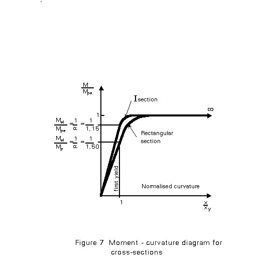
= Mpl/Mel = Wpl/Wel (4)which, for example, equals 1,5 for a rectangular section, 1,7 for a solid circular section, while varying between 1,12 to 1,18 for I and H beams and channels bent about their strong "yy" axis.
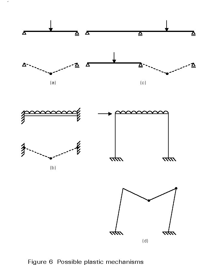
When the load on a structure increases, yielding occurs at some locations and the structure undergoes elasto-plastic deformations. On further increase a fully plastic condition will be reached at which a sufficient number of full plastic sections are formed to transform the structure into a plastic mechanism (Figure 6); this mechanism will collapse under any additional loading. A study of the failure mechanism and the knowledge of the associated magnitude of the collapse load are necessary to determine the load factor in analysis. Alternatively, if the load factor is specified, the structure can be designed so that its collapse load is equal to, or higher than, the product of the load factor and the reference service loading. Plastic analysis implies, therefore, not only plastic stress distribution within the cross-section (plastic hinge formation), but also sufficient bending moment redistribution in order to develop all the plastic hinges that are required to give rise to a plastic mechanism.
When yielding develops within a cross-section, the cross-section's effective value of flexural stiffness, EI, decreases progressively (Figure 7); indeed, the effective modulus of the yielded material is zero when assuming the perfectly plastic behaviour beyond yield, hence the term "plastic hinge". Once this hinge is produced, the structure will behave, under additional loading, as if a real hinge was introduced at the yielded section. The onset of the first plastic hinge in a structure results in a reduction of the original redundancy by one; any additional plastic hinge will have a similar effect.
Collapse occurs after sufficient plastic hinges have formed to convert the original redundant structure into a progressively less redundant structure, and finally into a mechanism.
In a statically determinate structure, the gain in strength due to plasticity depends on the value of the shape factor. In a statically indeterminate structure, it is affected by the process of moment redistribution.
The ability of a structure to redistribute stress within the cross-section, and between cross-sections, requires that no other form of failure occurs before the plastic collapse mechanism, so that the ultimate load can be reached. The following requirements must be met for plastic analysis to be allowed:
To comply with these requirements, limits must be placed on the type of steel and the proportions of the members and cross-sections. Currently, plastic design is permissible for the usual grades of mild steel, while for other grades a minimum length of the yield plateau and a minimum ratio between the ultimate tensile strength and the yield stress (strain hardening) are required. Members containing plastic hinges must satisfy limitations on flange and web proportions; these are more restrictive for higher steel grades. Because yielding results in a large reduction in stiffness, members where plastic hinges occur are especially prone to failure by member instability; therefore, there are severe limits on the slenderness of such structural elements resulting in a need for appropriate lateral bracing, especially at the plastic hinge locations.
The above implies that the ultimate bending resistance of a section is defined solely by its plastic moment; axial load and shear force, however, will have an effect as discussed in Lecture 7.8.1.
In a structure subject to a specified loading, whose magnitude is increased up to collapse, the sequence of hinge formation is fixed. However, factors such as settlement, variability of material strength between members, residual stresses, thermal effects, etc., can change the sequence while not significantly affecting the plastic collapse load; the latter, indeed, is statically determinate and does not depend on structural imperfections of any kind.
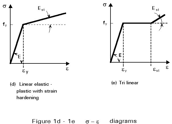
Plastic analysis is based on non linear material behaviour, even where geometric second order effects are negligible. Hand analysis methods are based on the fundamental theorems of the plastic design, which usually neglect elastic curvatures, compared to plastic ones, and concentrate plastic deformations at plastic hinge locations; they use, therefore, rigid-plastic methods (Figure 1c). Information regarding this subject is not within the scope of this lecture and the reader is referred to the literature quoted in Section 6 for further discussion on this matter. Computer methods are less dependent on idealisations and may therefore be based on more realistic material stress-strain relationships accounting for elastic curvatures and deformations. These are termed elastic-plastic and can be distinguished from the perfectly plastic approach, characterised by an infinite yield plateau (Figure 1c), by a slight slope in the yield region (Figure 1d), or by a strain-hardening range following a yield plateau of limited length (Figure 1e). Alternatively, even more precise relationships may be adopted; nowadays, refined finite element programs allow for the spread of yielding and the concept of plastic zones is used instead of plastic hinges.
Second order plastic analysis generally requires the use of computer programs; the collapse load of multi-storey sway frames may however be determined using the Merchant-Rankine formulae, which take into account, in a very simple manner, the interaction between elastic buckling and yielding.
It is worthwhile emphasising that because plastic analysis is essentially nonlinear, the principle of superposition is not, therefore, applicable.
It should be noted that assumptions made in the global analysis of the structure should be consistent with the anticipated behaviour of the connections. The assumptions made in the design of the members should also be consistent with (or conservative in relation to) the method used for the global analysis and the anticipated behaviour of the connections. More detailed information in this respect will be provided in the lectures devoted to the design of connections.
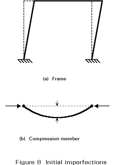
Current codes and standards require that appropriate allowances shall be incorporated in the global analysis to cover the effects of residual stresses and geometric imperfections, such as lack of verticality, lack of straightness, lack of fit, and the unavoidable minor eccentricities present in practical connections. Suitable equivalent geometric imperfections may be used, with values which reflect the possible effects of all types of imperfections (Figure 8).