ESDEP WG 7
ELEMENTS
To introduce the basic ideas of frame behaviour as a prelude to the more detailed description of design in later lectures.
Lectures 1B.7: Introduction to Design of Multi-Storey Buildings
Lectures 6.6: Buckling of Real Structural Elements
Lecture 7.1: Methods of Analysis of Steel Structures
Lecture 14.2: Analysis of Portal Frames: Introduction and Elastic Analysis
Lecture 14.3: Analysis of Portal Frames: Plastic Analysis
Lecture 14.8: Classification of Multi-Storey Frames
Lecture 14.9: Methods of Analysis for Multi-Storey Frames
Lecture 14.10: Simple Braced Non-Sway Multi-Storey Buildings
Lecture 14.13: Design of Multi-Storey Frames with Partial Strength and Semi-Rigid Connections
Lecture 14.14: Methods of Analysis of Rigid Jointed Frames
Techniques for the determination of the individual member forces in steel frames are described and discussed. These techniques include first and second order approaches based on both elastic and plastic theory. The different approaches to the design and construction of steel frames permitted by Eurocode 3 [1] are explained and their implementation outlined.
Frames of varying size and complexity represent one of the most frequent uses of structural steel. Whilst the most obvious application is in buildings, support frames for bridges, offshore platforms, falsework and industrial storage systems also constitute a significant usage.
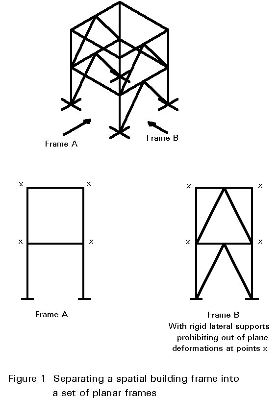
The main components of a rectangular arrangement are identified in Figure 1. Vertical loads on the roof and floors are transmitted by bending and shear into the columns, which, in turn, transfer load into the foundations by means of compressive, bending and shearing actions. Horizontal loading, e.g. due to wind, must also be transferred into the foundations and may, depending upon the frame geometry and the relative magnitudes of the vertical and lateral loads, induce tension in some columns and therefore uplift on the foundations.
In general, a 3-dimensional building frame may be separated into a set of planar frames with well-defined support or restraint conditions for out-of-plane deformations, see Figure 1. These planer frames should be investigated for two different limit state conditions:
Details of these investigations are provided in later lectures. In this introductory lecture attention is focused on describing the main aspects of frame behaviour and the ways in which these aspects are linked to various techniques for predicting structural response. The lecture is a preparation for later more detailed treatments.
For the purposes of analysis and design, steel frames have traditionally been regarded as belonging to one of two categories:
Of course, examples exist for which elements of both types are present; the present discussion does not consider these cases in developing the subject.
In Eurocode 3 this simple subdivision has been extended by including consideration of the method of analysis and including joints that behave as semi-rigid. This leads to the more complex classification system that is shown in Table 1.
|
Type of framing |
Method of global analysis |
Types of connections |
|
Simple |
Pin joints |
× Nominally pinned× Nominally pinned |
|
Continuous |
Elastic |
× Rigid× Nominally pinned |
|
Rigid-Plastic |
× Full-strength× Nominally pinned |
|
|
Elastic-Plastic |
× Full-strength - Rigid× Nominally pinned |
|
|
Semi-continuous |
Elastic |
× Semi-rigid× Rigid× Nominally pinned |
|
Rigid-Plastic |
× Partial-strength× Full-strength× Nominally pinned |
|
|
Elastic-Plastic |
× Partial-strength - Semi-rigid× Partial-strength - Rigid× Full-strength - Semi-rigid× Full-strength - Rigid× Nominally pinned |
Table 1 Methods of framing and global analysis in Eurocode 3
This introductory lecture does not cover the cases where the joints are semi-rigid. Further information on this type of joint and their influence on frame design is given in Lectures 11.7 and 14.13.
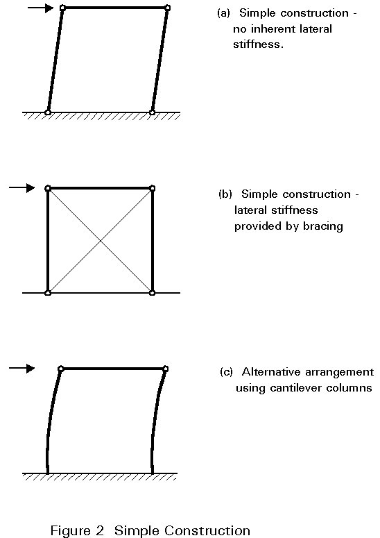
Building frames designed and executed according to this principle require comparatively little analysis as the loads may be allocated to individual members on the basis of simple statics. Since the joints are assumed to be incapable of transmitting moments, lateral stability requires the use of bracing because a rectangular bay with pinned beam to column connections, of course, possess no lateral stiffness. The only exception to this condition is when the feet of the columns are rigidly fixed to a solid foundation so that they can function as vertical cantilevers. Figure 2 illustrates these points.
Once the forces in the members have been decided upon, design may be conducted by considering individual beams, columns and joints, using the procedures presented in Lectures 7 and 11 respectively. All horizontal loading is assumed to be resisted by the bracing system and, in the terminology of Eurocode 3 [1], the structure is designed as a braced frame.
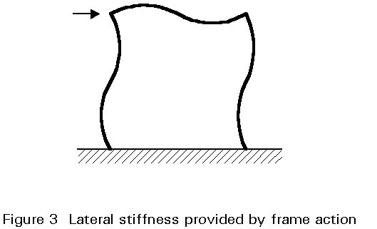
When rigid joints are used, considerable interaction between beams and columns occurs due to transfer of moments around the frame. Various approaches to analysis and design may be employed; the most important consideration is the extent to which the effects of deflections on the response of the frame must be taken into account. Although rigid joints may be used in conjunction with bracing, construction economies make this arrangement an uncommon solution. Rigid joints are normally only used as an alternative to bracing so that lateral stiffness is provided by so-called frame action as illustrated in Figure 3.
In first-order elastic analysis a linear relationship between the applied loading F and the deformations (d) is assumed. The internal force distribution in the frame is assumed to be unaffected by the displacements in the frame.
Frame analysis can therefore be conducted according to linear elastic principles as outlined in Lecture 7.1. The frame responds according to line 1 in Figure 4.
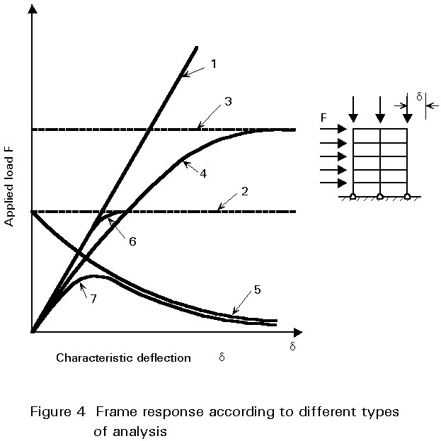
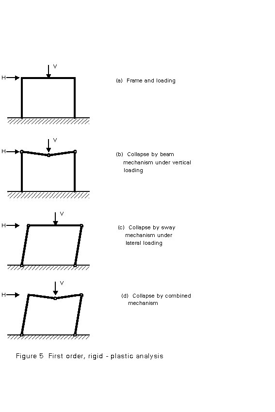
Rigid-plastic analysis (or the application of simple plastic theory) neglects the effects of elastic deflections and assumes that all structural deformation takes place in discrete regions, called plastic hinges, where plasticity has developed. When using first-order, rigid-plastic theory only the collapse condition is addressed. This condition occurs when sufficient plastic hinges are assumed to have formed to convert the structure into a mechanism. Thus the path by which this stage is reached, i.e. the sequence of formation of the hinges and any intermediate distributions of internal forces, are not considered. Figure 5 illustrates the concept for 3 cases of vertical, horizontal and combined loading, whilst curve 2 in Figure 4 gives the frame response according to this approach. Due to the form of the analysis, no information is provided on the magnitude of the deflections. The analysis gives only that all stiffness is lost at the collapse load and deflections therefore (in theory) become uncontrolled.
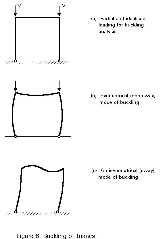
Using the methods described in Lectures 6, it is possible to calculate the buckling loads for frames under suitably idealised loading. Depending upon the content and complexity of the frame, several different buckling modes, each with its associated elastic vertical load, may be possible. For the simple portal frame shown in Figure 6, both a symmetrical and an antisymmetrical mode are possible; the latter will usually be avoided with a much lower critical load. Once again the analysis provides no information on the magnitude of the deflections; it simply identifies a particular load level. The curve 3 in Figure 4 gives the representation of the critical load obtained by an elastic buckling analysis.
In second-order elastic analysis the effect of elastic deformations on the internal force distribution is taken into account. The result is a transition from the linear analysis line 1 at low loads to the elastic critical line 3 at large deflections. For frames the second-order effects may be separated into 2 parts:
If the deformations that may develop as a result of the formation of the plastic collapse mechanism are allowed for when formulating the equilibrium of the frame, then the result is the developing mechanism curve of line 5 in Figure 4. This curve shows that equilibrium can only be maintained with a reduction in the level of the applied loads.
If a linear elastic analysis is modified to allow for reductions in frame stiffness with the progressive formation of plastic hinges at increasing levels of the applied load, then the response curve of line 6 is obtained. This line exhibits progressive loss of stiffness as each plastic hinge is formed and eventually merges with the rigid-plastic line 2.
When the analysis that traces the formation of plastic hinges also allows for the effects of deformations in setting up the governing equations, then line 6 is modified somewhat into line 7. Line 7 initially follows the first-order elastic line 1 but diverges from this line to follow the second-order elastic line 4 as destabilising effects become more significant. Formation of the first plastic hinge - which occurs at a slightly lower applied load than is the case with the first-order, elasto-plastic analysis due to the larger deformation associated with second-order analysis - further reduces the stiffness, causing line 7 to diverge from line 4. This divergence becomes more pronounced as more plastic hinges form. The peak of this curve corresponds to the failure load predicted by this type of analysis. At large deformations line 7 tends to merge with the curve for the mechanism, line 5.
If the spread of plasticity both through the cross-section and along the member length is taken into account, instead of assuming that it is concentrated into the desirable regions of the plastic hinges, then the resulting type of analysis is usually termed plastic zone theory. It provides an even closer representation of actual behaviour and leads to a curve similar to line 7.
In principle, any of the above approaches to frame analysis may be adopted. In practice, some of the effects may be found to be of little real significance for certain classes of structure, e.g. for many low-rise frames second-order effects are very small and may reasonably be neglected. Certain cases may also arise where particular forms of response should be avoided, e.g. for buildings containing heavy cranes which will cause repeated loading, elastic design is normally employed.
The more complex approaches will almost certainly require the use of suitable computer software to implement the volume of calculation. It is therefore important to select an approach which is compatible with both the accuracy required and the level of importance of the project under consideration.
When calculating deflections at working load levels for the purpose of checking serviceability, it is usual to employ only linear elastic analysis.
In order to provide guidance on the most appropriate type of analysis to use in particular cases, Eurocode 3 has introduced the idea of frame classification [1]. A double condition is used:
This may be further quantified as:
For such frames first-order elastic or plastic theory should be used.
When the above conditions are not satisfied the frame must be considered as unbraced.
When designing the bracing system:
- any horizontal loads applied to the frames which it braces.
- any horizontal or vertical loads applied directly to the bracing system.
- the effects of the initial sway imperfections (or the equivalent horizontal forces) from the bracing system itself and from all the frames which it braces.
An unbraced frame may be classified as a non-sway frame according to Clause 5.2.5.2 of Eurocode 3 [1] providing:
This classification may be further quantified as:
VSd /Vcr £ 0,1
where VSd is the design value of the total vertical load.
Vcr is its elastic critical value for failure in a sway mode.
![]()
where d is the horizontal displacement at the top of the storey, relative to the bottom of the storey.
h is the storey height.
H is the total horizontal reaction at the bottom of the storey.
V is the total vertical reaction at the bottom of the storey.
Both requirements follow from the idea that, if satisfied, the load-carrying resistance determined by neglecting sway effects will be only a ten per cent less than that calculated by including such effects. This approach is, in turn, based upon the Merchant-Rankine concept for estimating the true ultimate load of a frame that fails by some from of inelastic instability from a knowledge of its elastic critical load and its first-order, rigid-plastic collapse load. Both loads are relatively straightforward to calculate.
The original Merchant-Rankine formulae for the failure load Vsd is:
![]()
where:
Vcr is the elastic critical load.
Vpl is the first-order, rigid-plastic collapse load.
From this it is clear that when Vcr >> Vpl, then Vsd ~ Vpl.
Non-sway frames should be designed using first-order elastic or plastic theory to resist safely the arrangements of loads that lead to the most severe combinations of internal forces and moments in the individual members and connections. The effects of restraint to columns in improving their stability should be taken into account by using the concept of effective buckling length as explained in Lecture 7.7.
Frames that do not meet the above requirements must be designed as sway frames.
Sway frames shall be analysed under those arrangements of the variable loads which are critical for failure in a sway mode. In addition, sway frames shall also be analysed for the non-sway mode.
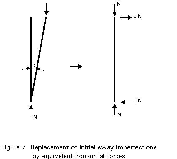
The initial sway imperfections, and member imperfections where necessary, shall be included in the global analysis of all frames.
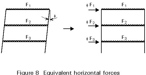
The allowance for imperfections in the analysis of sway frames is intended to cover effects such as lack of verticality, lack of straightness, residual stresses, etc. It is expressed in Eurocode 3 by means of a set of equivalent geometrical imperfections [1]. These imperfections are not actual construction tolerances but, because they are intended to represent the effect of a number of factors, are likely to be larger than such tolerances. The form specified in Eurocode 3 is:
f = kc ks fo
with fo = 1/200
kc = [0,5 + 1/nc]0,5 but kc £ 1,0
and ks = [0,2 + 1/ns]0,5 but ks £ 1,0
where nc is the number of columns per plane.
ns is the number of storeys.
First-order or second-order analysis may be used. If the analysis is first-order, second-order effects may be allowed for in an appropriate way when designing the columns by using the results of a first-order analysis and either:
- using amplified sway moments, or
- using the sway-mode buckling lengths.
![]()
where VSd is the design value of the total vertical load.
Vcr is its elastic critical value for failure in a sway mode.
![]()
where d, h, H and V are as defined previously.
Rules for the application of plastic analysis procedures to sway frames are given in Clause 5.2.6.3 of Eurocode 3 [1].
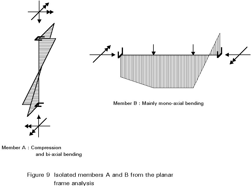
Satisfying the verification rules for resistance and stability of frames has to assure that neither the frame as a whole, nor the isolated members in the frame on their own, will collapse under a load which is smaller than the design load. For the safety verification of the individual members, the members may be separated from the frames to be dealt with as independent isolated sub-structures. The end conditions of the members should then comply with the deformation conditions of the members in the special frame in a conservative way (e.g. by assuming nominally pinned end conditions) and the interaction effects at the ends of the members should be considered by applying equivalent end moments and end forces, see Figure 9.
If, in a second-order elasto-plastic calculation, the real behaviour of the frame has been approximated and local instability and out-of-plane buckling is prevented, then further verification is not needed. In this case the strength check - also called the cross-sectional check - is implicity satisfied by working with the actual distribution of forces and moments. This is also valid for the stability check. It has to be shown that the equilibrium is stable under the design load. In other words: VSd representing the design load, must be less than the elasto-plastic collapse load Vk.
If the distribution of forces and moments, as a result of the design load, is calculated with a first-order elastic method, then it is quite possible that the actual elasto-plastic resistance Vk of the frame is exceeded. Verification rules to overcome this problem are therefore needed. On the one hand, cross-sectional checks are needed, to show that each cross-section can offer enough resistance to withstand normal forces, shear forces and bending moments due to the design load. On the other hand, stability checks are necessary to show that every member and the frame as a whole are stable.
In general, for each method of calculating the distribution of forces and moments, additional verification rules are necessary related to the specific method of calculating the distribution of forces and moments. All collapse mechanisms which are relevant for the frame and which have not been taken into account in calculating the distribution of forces and moments, should be checked by using adequate verification rules.
If a frame can deform only in its own plane and plate buckling (of web and/or flange), torsion, torsional buckling and lateral-torsional buckling are not relevant, then there are only two types of verification rules of importance: cross-sectional checks and stability checks. Depending on the method of calculating the distribution of forces and moments, specific verification rules must be taken into account. Table 2 shows that these rules depend on the calculation method used.
Table 2 Relation between global analysis and code check
|
Method for calculation the forces and moment distribution |
Cross-sectional verification rules |
Stability checks |
|
First-order elastic First-order plastic Second-order elastic Second-order plastic |
YES NO YES NO |
YES YES NO NO |
When the method of calculating the distribution of the forces and moments is relatively simple, the verification rules are complex and the other way around. In general verification rules for members are used in the step after the calculation of the distribution of forces and moments in a frame.
i. simple construction - assumed joints act as if pinned.
ii. continuous construction - assumed joints act as if rigid.
i. braced.
ii. unbraced and non-sway.
iii. unbraced and sway.
Each approach has been outlined, including the treatment of imperfections and the link between the approach adopted to consider overall frame behaviour and that necessary when considering individual members.
[1] Eurocode 3: "Design of Steel Structures": ENV 1993-1-1: Part 1.1, General rules and rules for buildings, CEN, 1992.
Chapter on stability.
Chapter on frames.