ESDEP WG 14
STRUCTURAL SYSTEMS: BUILDINGS
To present the basic principles of design of portal frames using elastic analysis; the scope includes tapered portal frames. The lecture is illustrated by a design example.
Lectures 2.3: Engineering Properties of Steels
Lecture 2.4: Steel Grades and Qualities
Lectures 3.1: General Fabrication of Steel Structures
Lectures 6: Applied Stability
Lecture 7.2: Cross-Section Classification
Lecture 7.3: Local Buckling
Lectures 7.9: Unrestrained Beams
Lectures 10: Composite Construction
Lecture 11.1.1: Connections in Buildings
Lectures 11.4: Analysis of Connections
Lecture 11.6: Moment Connections for Continuous Framing
Lectures 14.1: Single-Storey Buildings
Introduction; the economic advantages of using tapered, I-section portal frames with slender webs and Class 2 or 3 flanges; summary of fabrication methods with cross-references to fabrication lectures.
Methods of analysis for uniform and tapered portal frames; the need to consider bending moments envelopes and non-symmetric uplift conditions. Methods of resistance assessment for cross-sections. Slender webs under combined bending, shear and compression.
Connection design; requirements for secondary structure including bracing.
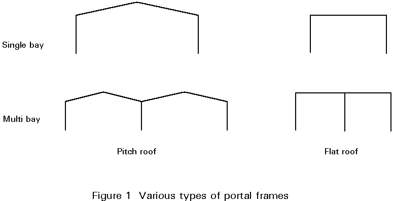
Portal frames are single storey, single or multi-bay frames with pitched or flat roof (Figure 1). This lecture presents the elastic analysis and design of portal frames, considering mainly the case of single bay and pitch roof, which is the most common in practice.
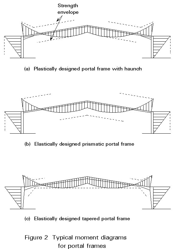
The next lecture presents the design of portal frames using plastic analysis. Where the frame comprises Class 1 rolled sections and the design is governed by strength, plastic analysis will lead to the greatest economy. As shown in Figure 2a, plastic redistribution is utilised to make maximum use of the frame resistance.
However, there are situations where plastic analysis cannot be used:
i. The frame comprises Class 1 sections but stiffness (deflections) governs design.
ii. The frame comprises Class 2 or higher sections.
Where prismatic sections are used, e.g. rolled sections, the elastic distribution of moments is such that the structure is relatively inefficient, as shown in Figure 2b. The beam section has to be chosen to satisfy the governing moment at the eaves; away from there the stresses in the beam are low.
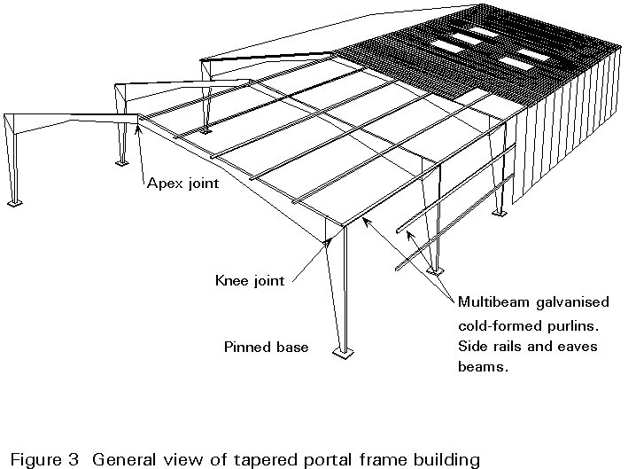
Economy of material is best achieved in an elastically designed frame by the use of tapered, welded sections. As shown in Figure 2c, the strength envelope can then be made a close fit to the bending moment envelope and stresses are high throughout the frame. Figure 3 shows a general arrangement of such as structural system [1].
Once the concept of using fabricated, non-prismatic members is accepted, the designer has the freedom to choose the following independent geometric parameters:
Some form of optimisation has to be used to determine these parameters, taking account of practical restraints. In practice it is found that greatest economy is generally obtained by using:
Class 2 or 3 flanges
Class 3 or 4 webs, with a maximum depth (d) to thickness (t) ratio up to 200, and without any stiffening.
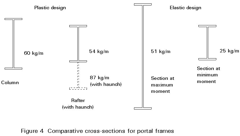
Within these restrictions considerable weight savings, compared to plastic design, can be achieved, as illustrated in Figure 4.
Of course minimising weight does not necessarily minimise cost. In this instance, overall economy of construction will only be achieved if automated fabrication is adopted. Recent developments in this context are summarized later in this lecture.
The behaviour of sections with slender elements is inherently more complex than that of stocky Class 1 sections, due to local buckling and cross-section distortion. Special design procedures are required and more attention has to be devoted to stabilising the frame by appropriate bracing from the secondary structure. These topics are addressed later in the lecture. The complexity of these strength checks and the greater complexity of analysis make it essential that computer aided design is adopted.
Thus, before tapered portal frames can be contemplated, a considerable investment is required in both automatic fabrication and computer aided design. Given this investment, there are considerable advantages in the use of welded tapered portal frames, compared to rolled section portal frames:
The elastic analysis of prismatic portal frames may readily be carried out by computer. Manual methods and charts [2,3] are also used.
The analysis of tapered portal frames is somewhat more complex. The variation of stiffness around the hyper-static frame influences the distribution of moments and associated shear and axial forces. Procedures for manual analysis do exist [4] but in practice analysis is usually carried out by computer. Figure 5 shows a typical analytical model; beams and columns are divided into shear elements; each element is considered as a prismatic member and is assigned the average properties over its length. The analysis provides a full distribution of moments, shear and axial forces of each element.
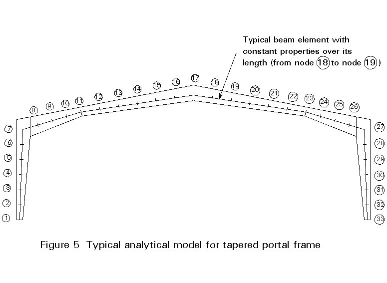
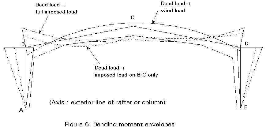
With tapered sections, economy dictates that section depth, and therefore resistance, are locally reduced where possible. For example, location 11 in Figure 5 is at a point of contraflexure under symmetrical vertical loading. These zones of reduced resistance do not exist in prismatic frames and designers are therefore not accustomed to thinking about the full envelope of bending moments on such frames. Figure 6 illustrates the bending moment envelopes that exist on a typical tapered frame. It is clear that, near to regions of minimum depth it may be pattern loading and other non-symmetrical cases that govern the design.

Under the combinations of actions to be considered for serviceability limit states, Eurocode 3 [5] recommends that the deflections of portal frames do not exceed the following limiting values:
for portal frames without gantry frames : h/150
for other single storey buildings : h/300
where h is the height of the column.
where L is the span of the beam
Usually, for portal frames with a pitched roof, the deflection criteria for beams is not a critical one.
All roofs with a slope of less than 5% should be checked to ensure that rain water cannot collect in pools. In this check, due allowance should be made for possible construction inaccuracies and settlements of foundations, deflections of roofing materials, deflections of structural members and the effects of precamber, if any.
Where the roof slope is less than 3%, additional calculations should be made to check that collapse cannot occur due to the weight of water collected in pools which may be formed due to the deflection of structural members and roofing material or retained by snow.
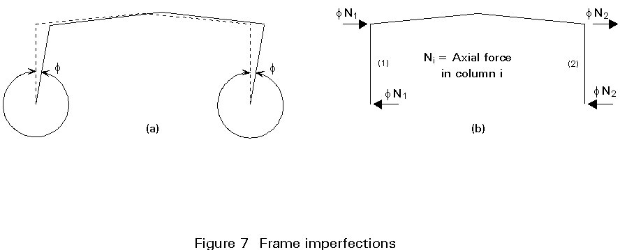
For ultimate limit states calculations, the effects of frame imperfections should be allowed for in global frame analysis by means of an equivalent geometric imperfection in the form of an initial sway (Figure 7a) determined from:
F = {0,5 + 11nc}0,5 1200 |
where nc is the number of columns for single bay portal frames |
|
= 1/200 |
In practice, it is more convenient and accepted in Eurocode 3 [5], to replace the initial sway imperfection by a system of equivalent horizontal forces, as shown in Figure 7b.
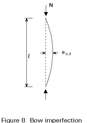
Member imperfections are taken into account when carrying out the global frame analysis by incorporating the appropriate bow in the columns, as shown in Figure 8. The value eo,d of the bow depends on the type and dimension of the column section, and is given in Eurocode 3 [5].
The member imperfections may not be considered in the global frame analysis when
![]() < 0,5 {Afy / Nsd}0,5
< 0,5 {Afy / Nsd}0,5
where Nsd is the design value of the compressive force
![]() is the in-plane non-dimensional slenderness calculated using a buckling length equal to the system length.
is the in-plane non-dimensional slenderness calculated using a buckling length equal to the system length.
Second order global analysis, including frame imperfections (sway or horizontal forces) and member imperfections (bow) is the most exact and convenient method for portal frames with tapered members. Some existing computer software will automatically:
After having obtained the results of the computer calculation, there is no need for further hand calculation of effective length and in-plane buckling of members. The only checks needed are:
If the frame comprises Class 4 sections, the reduced effective cross-section must be determined. This does not apply to Class 1, 2 and 3 sections.
As the second order analysis is non-linear, the composite calculations must be carried out for all the load combinations. There is no possibility of superposing the effects of elementary loads.
The so-called 'simplified methods' of analysis can also be adopted, but they present several disadvantages:
In these 'simplified methods' a first order global elastic analysis is performed by computer calculations (or by hand, but only for prismatic members, single bay portal frames) taking into account frame imperfections (usually horizontal forces).
As single bay portal frames are not very stiff, they must usually be classified as sway frames. For most load cases this situation occurs when:
Vcr < 10 Vsd
where Vsd is the design value of the total vertical load
Vcr is its elastic critical value for failure in a sway mode.
After the first order global analysis has been carried out, two possibilities for complementary hand calculations are found in Eurocode 3:
First Possibility - "Amplified sway moments" method
Second Possibility - "Sway mode buckling lengths" method
The formulae that have to be applied for points 2 and 3 (buckling lengths and buckling resistance) are given in Eurocode 3 for prismatic members, but they do not apply to tapered members. Approximate conservative solutions may be used for tapered members.
Finally the complementary checks presented for the second order global analysis must also be done by hand calculation, i.e. stresses, out-of-plane buckling and lateral-torsional buckling.
If the frame comprises Class 4 sections, the reduced effective cross-section must be determined.
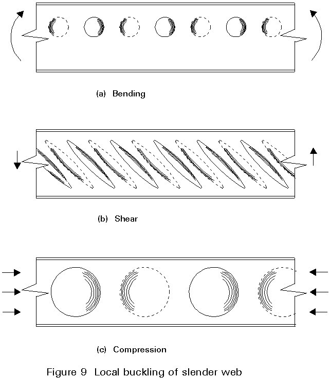
The web slenderness (d/t) may be as high as 200. The web is therefore subject to local buckling under bending, shear and compression of the type shown in Figure 9. This form of instability does not often occur in other forms of building structure.
Normally flanges are restricted to Class 2 or 3 and local flange buckling need not be considered.
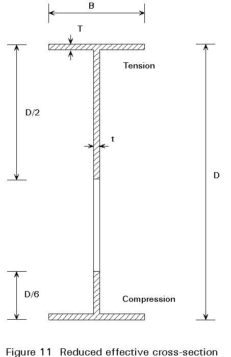
As shown in Figure 10 buckling of a rafter or column between stays is a complex interaction of local web buckling, lateral-torsional buckling and cross-section distortion. Recent studies [6] have considered these effects directly and resulted in advanced tentative design approaches. However, a much simpler model that provides good agreement with experimental results is that based on the reduced effective cross-section shown in Figure 11.
The strength check is then as follows:
i. Determine the stresses on the reduced effective cross-section from the bending and axial compression.
ii. Ensure the compressive resistance of the Tee section is greater than the applied compression, assuming that it has an effective length equal to the stay spacing.
iii. Check the tension flange to ensure that it is not yielding. Yielding will only govern if the section is highly non-symmetric.
iv. Check the resistance of the web under combined compression, bending and shear, using stress resultants for the first two actions that are based on i. above.
The behaviour of the eaves connection is best understood by following the development of the connection utilised by a leading UK fabricator [7]. Originally the diagonal connection plane shown in Figure 12a was considered. In-plane behaviour was satisfactory but there was a major stability problem at the inside corner. Lack of continuity between the flanges along the joint, exacerbated by any lack-of-fit from end-plate distortion, led to premature out-of-plane failure at this point. This problem could be controlled by direct staying to this corner but such a solution is costly in the absence of any convenient purlin or siderail for that stay.
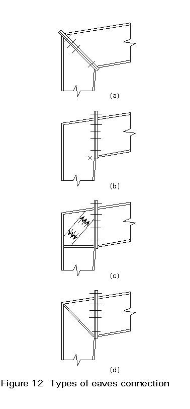
Stability of the inside corner for this elastic design can be achieved by continuing one or other of the inside (compression) flanges through to the relevant tensile load path, as shown in Figure 12b.
Generally some stiffening will be required at point X in Figure 12b. In the absence of a diagonal stiffener, because the corner panel is slender, the high corner shears are resisted by the tension field action shown in Figure 12c. A local reduction in effective lever arm results which will cause a sharp increase in compression in the immediate vicinity of the inside corner, causing premature failure. It was decided to provide a substantial diagonal stiffer, as shown in Figure 12d, which could resist the combined compression of the two flanges by direct triangulation of forces. This stiffener carries out the multiple functions of maintaining the lever arm around the corner, stiffening the flange so that it may resist the horizontal compression from the incoming flange and stabilising the slender web.
Traditional design criteria for stay forces are empirical. Typical design values are 21/2% of the maximum resulting force in the compressed area of the braced sections, distributed among the restraints along the length of the element. This approach has been demonstrated to be satisfactory by experience. However, the deep, slender sections that are a feature of tapered, fabricated frames, with a high ratio of Ixx to Iyy, are more prone to buckling. Previous work [7, 8] has suggested that a figure of 2% at each brace might be more appropriate.
The potential economic advantage of tapered portal frames can only be realised if the structural sophistication is matched by efficient office procedures and fabrication.
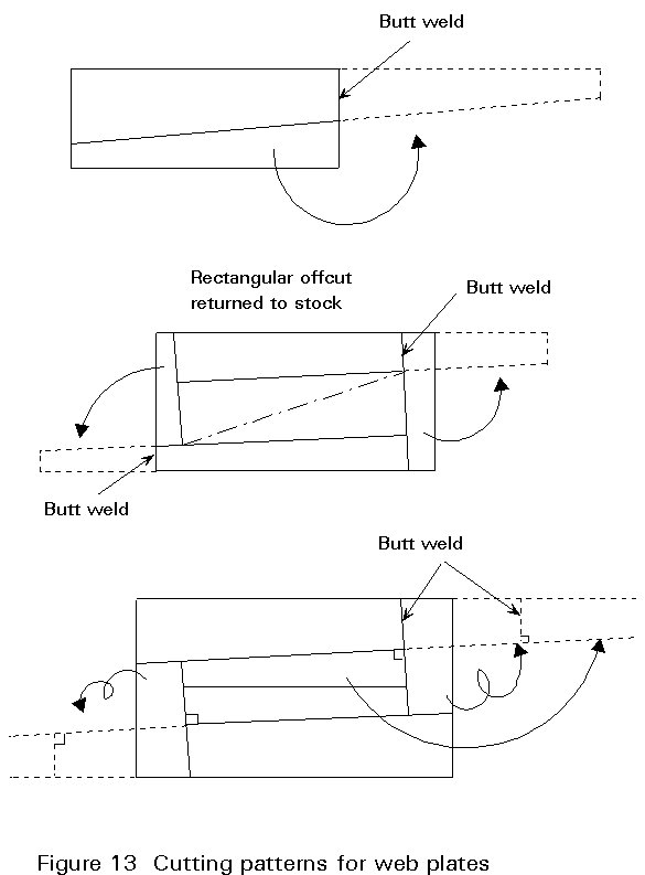
Design, drafting, estimating and stock control need to be computerised. The design procedures need to encompass analysis, resistance and serviceability checks and optimisation. Drafting should produce full drawings based on detailing guidelines specified by the workshop. As a by-product data is generated for all numerically controlled workshop machines. Accurate estimating follows readily from the foregoing data. At tender stage it can be used for the preparation of precise cost and time information without the preparation of full drawings and numerically controlled data. Stock control can be utilised to minimise waste; this is particularly important for the efficient cutting of tapered webs. Figure 13 shows a typical cutting pattern for a web plate. Use of stock materials can be introduced as a constraint on the design optimisation.
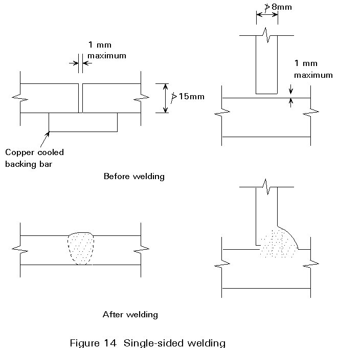
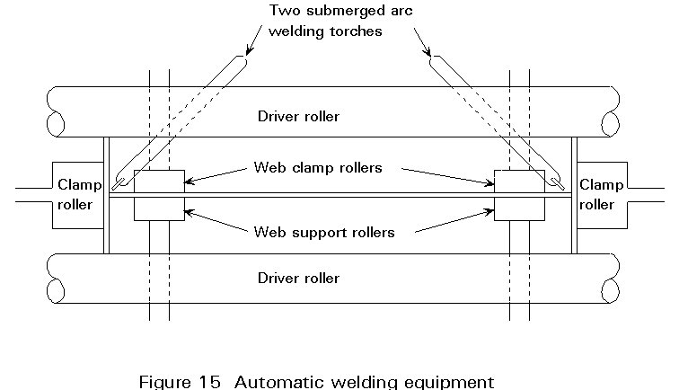
The heart of the semi-automatic fabrication is the efficient welding of the flanges to the web. Welding is usually based on the single-sided submerged-arc process shown in Figure 14. The essential features of the process are shown in Figure 15. Further details are given in Lecture 3.4 on Fabrication.
However, to achieve overall efficiency this manufacturing process has to be supported by:
[1] Dowling, PJ, Mears, T.F, Owens, G.W, and Raven, G.K. "A development in the automated design and fabrication of portal framed industrial buildings". The Structural Engineer, London, Vol. 60A. No. 10, October 1982.
[2] Kleinlogel, Mehrstielige Rahmen, Band I and II Berling, Verlag von Withelm, Ernst & Sohn.
[3] Owens, G.W and Knowles, P.R (Ed) "Steel Designers Manual" Blackwells Scientific Press, Oxford 1991.
[4] "Metal building systems manual", Cleveland, Ohio, Metal Building Manufacturers Association 1981.
[5] Eurocode 3: "Design of Steel Structures": ENV 1993-1-1, Part 1.1, General Principles and Rules for Buildings, CEN 1992.
[6] Chung, K.F and Owens, G.W., "Distortional Instability of very Slender Web Beams". Proc. Forth Rail Bridge Centenary Conference Developments in Structural Engineering Edited by B.H.V Topping, Chapman and Hall London Volume II, Pg 747-757.
[7] "Reference 1 discussion". The Structural Engineer, London, Volume 61A, Number 10, December 1983.
[8] Owens, G.W and Dowling, P.J., "Full scale testing of tapered portal frames". IStructE/BRE Seminar on Structural Assessment, BRE, Watford, England 1987.