ESDEP WG 14
STRUCTURAL SYSTEMS: BUILDINGS
To present the basic principles of portal frame design using the rigid-plastic method of analysis which are then demonstrated in a design example.
Lecture 2.3: Engineering Properties of Metals
Lecture 2.4: Steel Grades and Qualities
Lecture 7.2: Cross-Section Classification
Lectures 7.9: Unrestrained Beams
Lectures 7.10: Beam Columns
Lecture 11.6: Rigid Moment Connections for Buildings
Lectures 14.1: Anatomy & Analysis of Single Storey Buildings
Lecture 14.13: Rigid Jointed Frame Design
The basic principles of rigid-plastic analysis are presented with reference to plastic hinges, effects of combination of bending, ± axial forces and ± shear forces, "free" and "reactant" bending moment diagrams, hinge history and collapse mechanisms, and settlement of supports.
The principles are developed for a semi-continuous beam and extended to a flat portal and to a pitched portal. Design rules for a pitched portal frame are discussed followed by a design example.
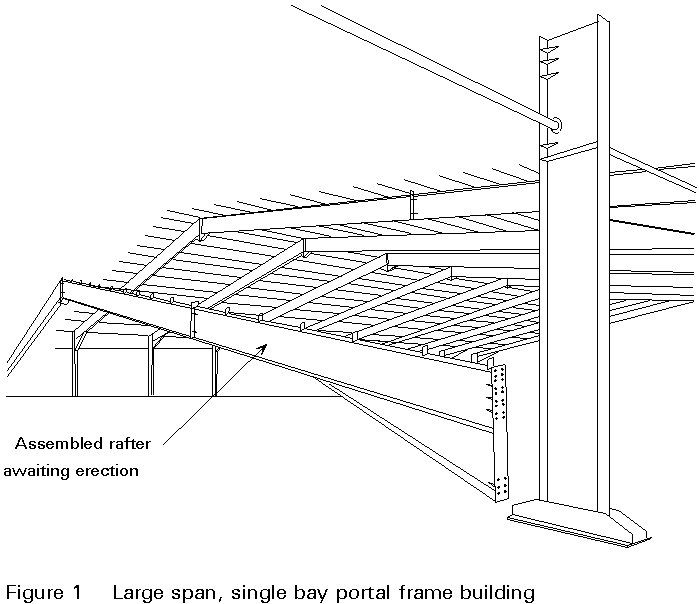
Figures 1 and 2 illustrate typical modern steel portal frame buildings.
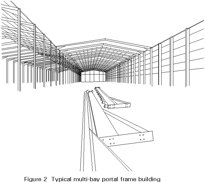
They may consist of:
In the UK such structures are frequently designed using the simple rigid-plastic method of analysis.
This lecture describes the design of portal frames fabricated from beams and designed using the simple rigid-plastic method of analysis. References to clauses in Eurocode 3 [1] are given in the text usually in brackets, e.g. (clause 5.3.1).
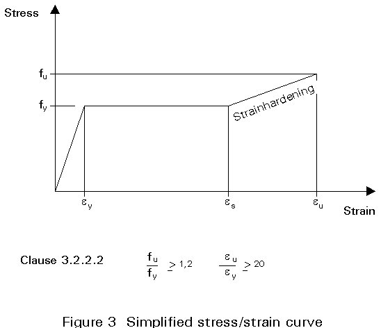
The use of the plastic method of analysis in the design of steel structures is possible due to the ability of structural steel to sustain considerable deformation without fracture. A typical stress/strain curve is shown in Figure 3.
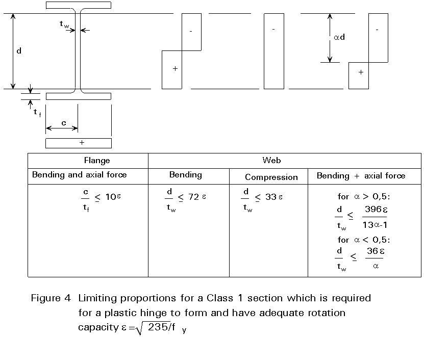
Beams subjected to bending moments must be symmetrical about the axis in the plane of loading, (Clause 5.3.3.(1)), and comply with certain dimensional properties for a plastic hinge to be developed and maintained, (Clauses 5.3.2 and 5.3.3). A summary of these criteria is shown in Figure 4.
In Figures 5a, 5b and 5c the development of a plastic hinge in an I-section is shown. Any attempt to apply more bending moment to the section, once the complete section is fully plastic, causes the member to act as if a hinge had occurred at that point.
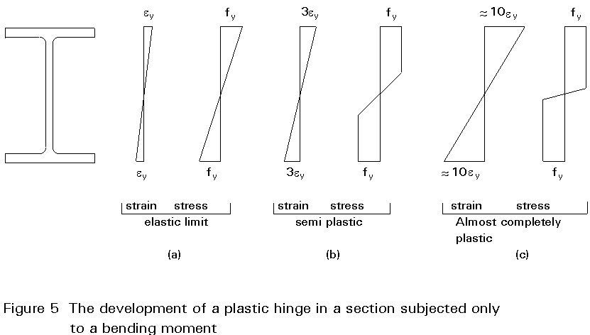
This hinge action is called a plastic hinge. At a plastic hinge the steel section maintains the plastic bending moment and also can undergo considerable joint rotation thus causing any additional bending moments to be transferred to other parts of the member or structure.
Figure 5 is for the situation where only a bending moment exists and the bending moment resistance at the plastic hinge condition is called the Plastic Moment of Resistance (PMR) of the section. In Clause 5.4.5.1:
Mpl.Rd = Wpl fy /gM0
= the design plastic resistance moment of the gross section
= PMR.
Fastener holes in the tension flange may reduce the PMR - see Clause5.4.5.3.
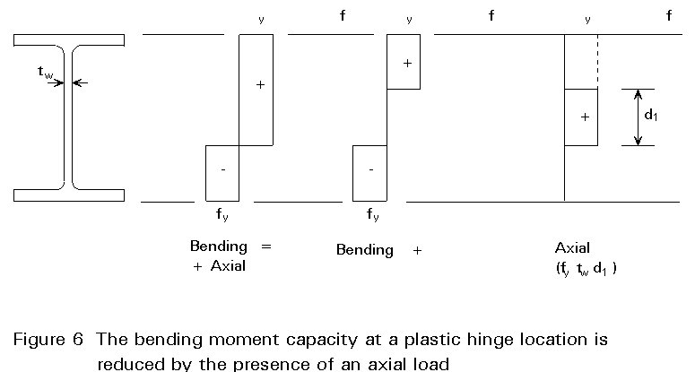
The PMR of a section is reduced when a bending moment is co-existent with an axial force or a large shear force.
In Figure 6 the stress distribution for bending and co-existent axial force is shown. It should be noted that an axial force usually causes only a small reduction to the gross section PMR. Typically an axial force of ![]() reduces the PMR by only 2%.
reduces the PMR by only 2%.
Formulae for the reduced PMR (MN.Rd) are given in Clause 5.4.8.
MN.Rd = Mpl.Rd [1 - (NSd /Npl.Rd )2]
For the design condition
MSd £ MN.Rd
The above equation can be re-arranged to give the following interaction equation:
Modified formulae for bending and coexistent shear are given in Clause 5.4.7. It should be noted that where the shear force < 50% of Vpl.Rd then the gross PMR is not reduced.
The predominant action effects in portal frame members are bending moments. Axial and shear forces usually have a negligible effect on the moment of resistance.
However large shear forces do occur in the column head as a result of the eaves haunch connection.
It is very common practice NOT to check the column head for the combined effect of bending moment and shear force even when the column has a bending moment plastic hinge in the column immediately below the column head.
However, it is common practice to stiffen the column head if the column web shear stress is > fy /Ö3, i.e. > 0,6 fy. The verification of this practice requires further clarification because it has been reported that, although post-yield strength can justify it, excessive deformation may occur due to second order effects on the portal frame [2]. The test reported in [2] does have a very high shear stress in the column web which is NOT appropriate to a typical portal frame column head.
It is necessary to have certain restrictions on fabrication to ensure that hardened material does not occur within the locality of a plastic hinge. Clause 7.3 lists restrictions relating to:
It is also specified that "All locations where restrictions on hardening are required should be clearly indicated on the drawings".
Plastic Design is for the ultimate limit state condition and includes structure and member stability checks. Serviceability limit state conditions also require checking.
In Figure 7 the beam has an elastic bending moment diagram with the maximum bending moment at Position 2. The first plastic hinge forms at Position 2 at a load of ![]() .
.
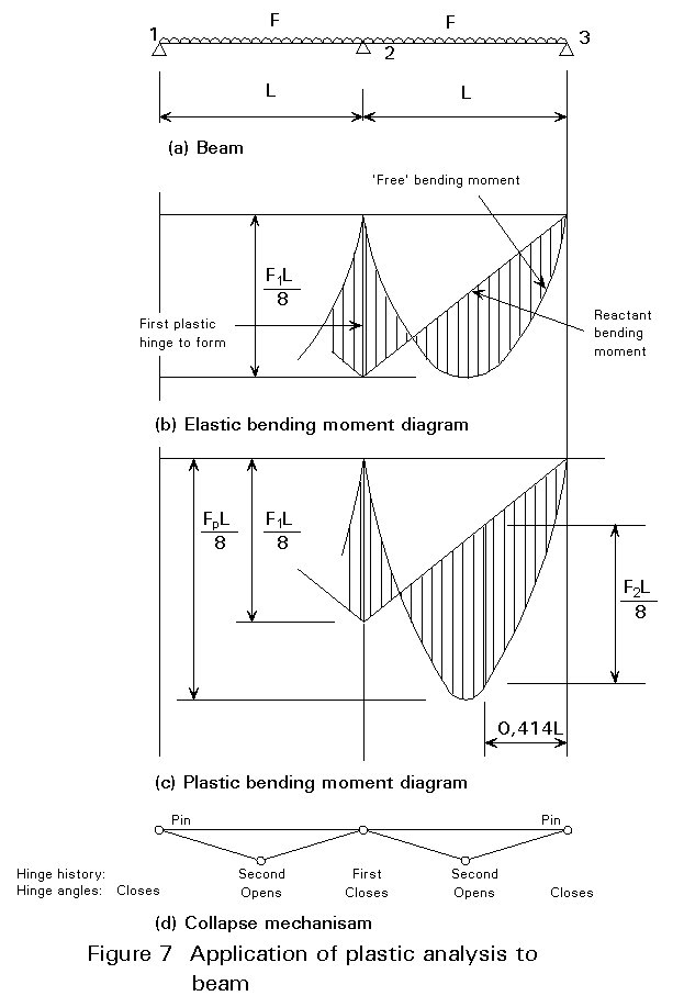
At this stage of loading only one plastic hinge has been formed and the beam has been reduced to two simply supported beams for any additional loading.
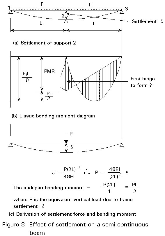
The effect of adding more loading is shown in Figure 8(c). This additional loading has the effect of causing a plastic hinge to form near the midspan of each beam. The exact position of the sag hinge can be determined and the value of the collapse load ![]() , i.e.
, i.e. ![]() .
.
If compared with an elastic analysis in which the section remains elastic, the additional resistance of adopting a plastic design for this particular example is:
![]() i.e. 67%
i.e. 67%
where ![]() is the shape factor (approx. 1,15 for an I section).
is the shape factor (approx. 1,15 for an I section).
However, if compared to an elastic analysis in which the full plastic resistance of the section is assumed (which is normally the case), the increase in strength by adopting a plastic analysis for this example reduces to:
![]() i.e. 45%
i.e. 45%
The shear force at Position 2 might reduce the PMR and therefore Fp.
In Figure 7(d) the plastic hinge history is shown. It can be seen that, if plastic hinges are not acceptable at working loads then, in this example the working load must not be more than ![]() times the collapse load.
times the collapse load.
In Figure 8(d) the collapse mechanism is shown from which it should be noted that:
The effect of foundation settlement on plastically designed structures is:
However the serviceability loading conditions should be checked for deflections and to determine whether or not a plastic hinge has formed. In Figure 8(a) the effect of settlement of the Support 2 is shown from which it can be seen that the hogging moment at Support 2 is reduced thus:
The load at which the first plastic hinge forms at Position 2 is:
F1 = ![]() (PMR + PL/2)
(PMR + PL/2)
where P is the equivalent vertical load due to frame settlement d .
Theoretically there is a possibility that the first hinge to form could be the sag hinge if there is a large enough settlement at Position 2.
Shear lag effects are covered in Clause 5.4.2.3 and apply to elastic and plastic analyses. If the length between points of zero moment is less than 10 times the width of the I beam flange then not all of the flange width is effective.
The above example illustrated in Figure 7 is for a beam that is in one continuous length from Support 1 to Support 3. If connections are introduced at Support 2, then reference should be made to Eurocode 3, Clause 6.9: "Beam-to-Column Connections".
Beam-to-column connections are classified by their moment resistance and rotational stiffness characteristics:
Moment resistance |
Rotational stiffness |
|
(Clause 6.9.6.3) |
(Clause 6.9.6.2) |
Nominally pinned |
Nominally pinned |
|
Full strength |
Rigid |
|
Partial strength |
Semi-rigid |
Full strength and partial strength can each be rigid or semi-rigid.
The example in Figure 7 can be classified thus:
|
Supports 1 & 3 |
Nominally pinned |
Nominally pinned |
|
Support 2 |
Full strength (plastic hinge) |
Rigid |
If at Support 2 the connection was "semi-rigid" then the moment of resistance of the connection might not be equal to the design plastic moment resistance of the connected beam and would therefore be "partial strength". It can be seen that if the Mf characteristics of the connection are too flexible, then the connection itself becomes a plastic hinge because the collapse mechanism moment has not reached Fp L/11,66. In such circumstances the moments at the other hinge positions are larger and a larger steel beam is required. The Mf characteristics also determine the hinge history and the deflections at serviceability limit state.
This discussion of the behaviour of a continuous beam includes some of the features of plastic design that have to be considered in the Plastic Design of Portal Frames.
As an example Figure 9(a) gives the general details a flat top portal frame. It can be seen that vertical and horizontal reactions are required at the pinned bases for the frame to perform effectively if analysed elastically or plastically. The value of H determines the position of the "reactant" bending moment on the bending moment diagram.
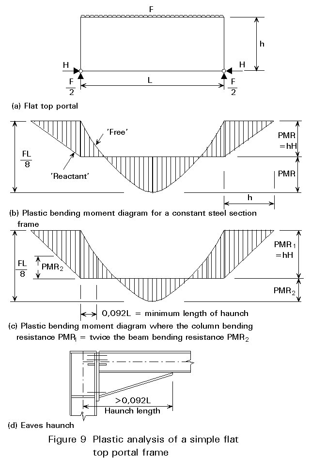
For elastic analysis the value of H is determined from the relative stiffnesses of the steel members. In contrast, for plastic analysis it is determined from the relative bending resistances. The analysis of the development of plastic hinges (the history) has to be checked for its effect on the serviceability performance of the frame.
In Figure 9(b) the beam and column are of the same steel section, whereas in Figure 9(c) the column has been arbitrarily chosen to have a bending resistance twice that of the beam. On Figure 9(c) it can be seen that the beam has to be strengthened at its connection to the column for a length of at least 0,09175L. This strengthening can be achieved by fabricating a haunch as shown in Figure 9(d). For stability reasons, the haunch is usually designed to remain elastic along its length when the frame is at the required ULS, see Annex A(c) iv.
It is not necessary or desirable to have both hinges PMR1 and PMR2 adjacent to the haunch. The effective length factor in the haunch stability check is a function of the values of the bending moments at the haunch ends [3]. The design in Figure 9(c) shows that for a haunch length » 10% of the span then the beam resistance need only be 50% of the column resistance. Depending on the frame span/height ratio this design can provide cost savings compared with the constant section solution from Figure 9(b).
The moment at the beam-to-column connection can be reduced by providing a 'weaker', or partial strength connection, (see Lectures 14.10 and 14.11). This reduction has the effect of increasing the size of beam required, but reduces the forces which are transferred through the connection. Where the connection has relatively low moment resistance, it may be possible to alleviate the need for a column web stiffener. Since the fabrication of stiffening elements can be a costly and labour intensive operation, overall economies may result.
In Section 4 the required PMRs of the sections are derived by the manipulation of the Bending Moment diagrams. The Principle of Virtual Work is an alternative method and requires the collapse mechanism to be assumed from which the steel sections PMRs can be calculated from the knowledge that:
S Mq = S Wd
Internal work done = External work done.
where each Mq = Plastic hinge PMR x hinge rotation.
and each Wd = Applied load x distance travelled.
The application to the first flat portal shown in Figures 9a and 9b is thus:
Assume mechanism based on Figure 9b and that the hinge rotation of the column head is q. Hence:
|
eaves |
midspan |
eaves |
|
|
S Mq |
= Mq |
+ 2Mq |
+ Mq = 4Mq |
S Wd = ![]()
4Mq = ![]()
M = ![]() = required PMR
= required PMR
So far only simple structures have been used as examples for the application of plastic analysis. The analysis method used is called the (simple) rigid-plastic method of analysis.
In Clause 5.2.1.4 three methods of plastic analysis are given. Their differences are summarised in Table 1.
Calibration of the elasto-plastic method has demonstrated that it is not necessary to use this more exact method for many (but not all) practical structural frames, including portal frames. Simple empirical rules have been developed that can be used with the rigid-plastic method and produce satisfactory economical designs.
From the previous Sections it can be seen that the simple rigid-plastic method of analysis is purely the manipulation of the bending moment resistances of the steel members by superimposing the "Reactant" bending moment on top of the "Free" bending moment. For portal frames this manipulation can be achieved by graphical means. This procedure was the sole means of design prior to electronic calculators and computers becoming available. This graphical method can be applied to virtually any loading combination, including hurricane winds.
As a consequence of the simplicity of the method, other criteria have to be checked as listed below:
a. Plastic hinges should preferably not form at the serviceability limit state because they would have to be taken into account when checking frame deflections. Frame deflections can be near to maximum acceptable limits and therefore the occurrence of plastic hinges is not desirable [4]. The occurrence of the first plastic hinge can be determined from an elastic analysis of the frame.
A Serviceability Limit State (SLS) for portal frames is specified in 4.2.2.(4) but consideration should also be given to the effect of the SLS deflections on side wall cladding or masonry and also the racking of the roof cladding in bays adjacent to stiff gable frames. There is no need to check the deflections of portal frames at loadings between SLS and ULS conditions.
b. For some frames and loading combinations it is possible for a plastic hinge to "form" and "unform" and not take part in any collapse mechanism. This phenomena should show up in computer programs based on the classical stiffness method where loading is incrementally "applied" to a frame and the plastic hinge history determined. Some computer programs have been reported to get this aspect wrong [4], and also to give incorrect results because of insufficient accuracy from the computer processor. An important point about "unformed" hinges is that they should be accounted for in the member stability checks.
c. The suitability of the simple rigid-plastic method of analysis to the actual portal frame being designed has to be determined because second order effects caused by the frame deflections might reduce the actual ULS resistance of the frame by too much.
Clause 5.2.6.3 permits simple rigid-plastic analysis to be used with an indirect allowance for second-order effects providing:
Elastic critical load ratio, VSd/Vcr £ 0,20
where VSd = design value of the total vertical load
Vcr = elastic critical value for failure in a sway mode
In the case of portal frames, this only applies to frames in which either:
· no plastic hinges occur in the columns, or
· the columns satisfy limitations on the in-plane slenderness given in 5.2.7.
The indirect allowance for second-order effects involves amplifying all the internal forces and moments by the factor in 5.2.6.2(3):
Application factor =
d. If VSd/Vcr £ 0,10, the frame can be classified as non-sway and provided it has adequate resistance to failure in a sway mode, no further checking for frame stability is required.
e. Most portal frames have elastic critical load ratios between 0,10 and 0,20. They are, therefore, sway frames and can be analysed by the simple rigid-plastic method provided the internal forces and moments are amplified. Amplification factors tend to be around 1,1.
f. Member stability has to be checked. The check is usually in the two areas of rafter haunch plus adjacent rafter and the columns, particularly where the compression flanges are unrestrained.
g. The loads applied to portal frames including wind loads, are usually classed as static loads. There is usually no need to check for alternating plasticity on building structures, see Clause 5.2.1.4.(11).
Annex A gives some design rules for simple portal frames.
[1] Eurocode 3: "Design of Steel Structures": European Prestandard ENV1993-1-1: Part 1.1 General rules and rules for buildings, CEN, 1992.
[2] Morris, L. J. and Newsome, C. P., "Bolted Corner Connection subject to an out-of-balance moment - The behaviour of the column web panel". International Conference, Teesside Polytechnic, Middlesborough, Cleveland - 6-9th April 1981. Additional Papers Volume.
[3] Draft Revision Amendment No. 2 to BS 5950: Part 1: 1990.
[4] Davies, J. M., "False Mechanisms in Elastic-Plastic Analysis". The Structural Engineer, page 268, August 1988.
[5] Morris, L. J. and Nakane, K., "Member Stability in Portal Frames", pages 305-336 of "Steel Framed Structures", Narayanan, R. Elsevier Applied Science Publishers.
Figure 10 shows the plastic bending moment diagram and collapse mechanism for a simple portal frame from which the following points are made and expanded into design rules:
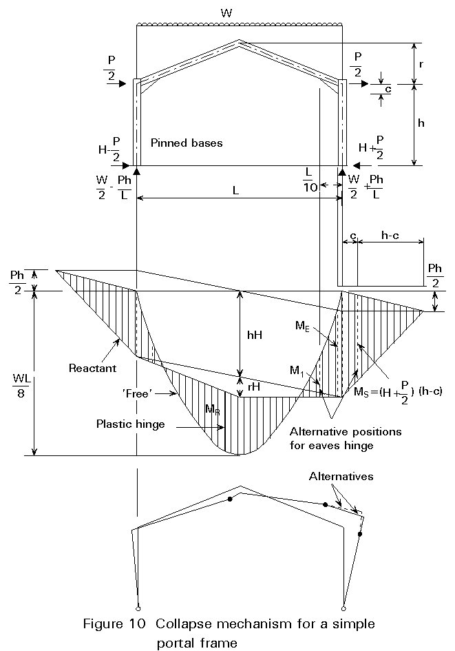
(a) The loading combination shown, of Dead + Snow + Equivalent Horizontal Forces (for frame imperfections), is usually the governing criterion but it does depend upon the intensities of Dead, Snow and Wind loads and the h/L ratio.
(b) Two plastic hinges are required in the actual portal frame to form a collapse mechanism since two other hinges are already available at the pinned bases.
The 'sag' hinge occurs in the rafter near the apex (MR).
The 'hog' hinge can occur in the rafter at the haunch toe (M1) or in the column (MS). The designer can usually choose which one by appropriate selection of column and haunch properties.
(c) The haunch is an important member and a number of points need to be considered (see also Figure 11):
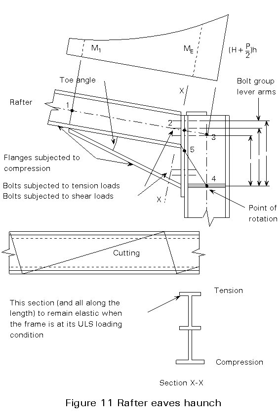
i. A haunch length of L/10 is a good first guess at what it should be. A shorter haunch increases the rafter section closer to the column section size, whilst a longer haunch reduces the rafter size but may cause problems in fabrication or in not being able to achieve the resistance ME.
ii. The haunch is usually fabricated from a cutting from another hot rolled section and welding it to the rafter and the end plate.
The cutting provides a "3 flange haunch" and is preferred to a "2 flange haunch" achieved from a plate insert because of its superior stability characteristics [5].
The toe angle should be kept above 7° to minimise distortion due to the effect of residual stresses that are "released" during fabrication.
iii. A cutting from the rafter section creates a symmetric section. Hence compressive stresses are high and may give rise to a need for closely spaced restraints to the cutting compression flange.
iv. The shape of the haunch and the bending moment diagram along its length causes it to be fairly constantly stressed and so a plastic hinge would form along the complete haunch length and may cause instability problems. One way of overcoming this is for the haunches to remain elastic along their complete lengths when the frame is at its required ULS.
If this approach is adopted, the haunch cutting compression flange is at lower stresses. Hence stability is easier to ensure without a lot of restraints. In addition, the frame stiffness is increased and SLS deflections are reduced.
v. The flange and end plates of the haunch connection are usually designed using yield line analyses. Other criteria, e.g. bolt prying loads, and local tensile stresses in the rafter web and welds, and the need for local stiffeners (Lecture 11.6), also need to be considered.
Grade 8.8 high tensile bolts are commonly used. The top group provide the tensile force which has a lever arm down to the point of rotation at the cutting compression flange. Other limiting factors on the size of bolts are dimensions for access for tightening, edge distances and the thickness of column flange and haunch end plate.
vi. All welds in a haunch connection should be fillet welds. Butt welds are more expensive and can create problems due to shrinkage, e.g. the point of rotation might move up from the required position.
vii. The haunch is designed as a rigid connection. Eurocode 3 [1] requirements for connections are given in Table 5.2.1. A portal frame being "continuous framing" and "rigid-plastic" global analysis requires a "Full Strength" connection in accordance with Clause6.4.3.2.
6.4.3.2 Subclause (1) requires the strength of a full-strength connection should be "at least equal to that of the member connected".
If the rotation capacity of a full-strength connection is limited, the design resistance of the connection must be at least 1,2 times the design plastic resistance of the member (6.4.3.2(2)) to allow for the possibility of the members being overstrength. However, the rotation capacity of a connection adjacent to a haunch need not be checked provided that the connection is capable of resisting the maximum moments and forces that would result if one or more of the plastic hinges located in the members were overstrength, due to the relevant members having an actual yield strength 1,2 times the specified value. For example, if the eaves hinge forms in the column, the moment resistance of the connection must be at least 1,2 times the plastic moment resistance of the column section. Member stability based on the new moment distribution would not have to be checked.
(d) If the 'hog' hinge is in the column (MS) then the stability check will require more restraints than if the column remained elastic. This can be important if the client requires full bay width doors in the side of a building.
(e) The modelling of the haunch in the frame analysis is shown by the dotted lines 1-2-3-4 for simplicity. An alternative is 1-5-4.
|
Criteria |
Rigid-Plastic |
COMPUTER BASED ELASTIC-PLASTIC |
|
|
Elastic-Perfectly Plastic |
Elasto-Plastic |
||
|
1. First Order Effects
i) Bending moments. ii) Effect of axial forces on member bending capacity. iii) Effect of shear forces on member bending capacity. |
* Optional
- |
* Optional
- |
* *
* |
|
2. Plastic Hinge Environment
i) Linear elastic members up to sudden formation of hinges at fyWpl. ii) Concentrated at hinge position. iii) Plasticity spreads across the section and partially along the member as the bending moment increases through fyWel to fyWpl. iv) Hinge history available. |
*
* -
- |
*
* -
* |
-
- *
* |
|
3. Second Order Effects in ULS Analysis
i) Deflections at main nodes due to first order bending moment effects. ii) No change in member EI values. iii) Loss of member stiffness due to combined effect of bending, axial (& shear?) forces AND member displaced shape. iv) Strain hardening at plastic hinge locations. |
-
* -
- |
-
* -
- |
included in iii
- *
* |
Table 1: Plastic analysis methods