ESDEP WG 14
STRUCTURAL SYSTEMS: BUILDINGS
Lecture 1B.1: Process of Design
Lecture 1B.3: Background to Loadings
Lecture 1B.5.1: Introduction to Design of Industrial Buildings
Lecture 9.1: Thin-walled Members and Sheeting
Lecture 14.1.2: Single-Storey Buildings: Envelope and Secondary Structure
Lecture 14.2: Analysis of Portal Frames: Introduction and Elastic Analysis
Lecture 14.3: Analysis of Portal Frames: Plastic Analysis
Lecture 14.4: Crane Runway Girders
Lecture 14.5: Space Structure Systems
Lecture 14.6: Special Single-Storey Structures
Single-storey steel buildings are used to accommodate many functions such as factories, leisure facilities, and supermarkets. The structure consists of several elements. The lecture examines the function of each element, gives general indications of the cost as a proportion of the total cost of the building.
The lecture also gives information on loading, on the different factors affecting the concept of the main frame, and on considerations relating to the construction process of the structure.
Steel construction is used for the majority of non-domestic single-storey buildings, the proportion is as high as 90% in the UK and 70% in France. This large proportion is due to the ability to design relatively light, long span, durable structures in steel which are easy to erect safely and quickly. The developments in steel cladding and light-gauge purlin and rail systems in recent years have enabled architects and engineers to create economical, attractive designs for a wide range of applications and budgets.
The rate of change of any activity is very rapid as technology develops. Clients expect therefore their buildings to have a lifetime several times longer than the initial layout. A primary requirement is therefore flexibility of planning which results in a demand for as few columns as possible. The ability to provide spans up to 60m, but more commonly around 30m, using steel has proved very popular for commercial and leisure buildings. The lightness and flexibility of this kind of steel structure reduces the sizes and the costs of foundations and makes them less sensitive to the geotechnical characteristics of the soil.
The brief for the design of the majority of single storey industrial buildings is essentially to provide a structure which is without, or has a limited number of, internal columns. In principle the requirement is for the construction of four walls and a roof for a single or multi-bay structure. The walls can be formed of steel columns with cladding which may be of profiled or plain sheet, precast concrete, or masonry. The designer considers a system of beams or frameworks (latticed or traditional) in structural steel to support the cladding for the roof. Use is made of hot rolled hollow sections (circular, rectangular) and traditional sections (I sections, angles, etc.) and also cold formed sections.
Light latticed frameworks for the roof of an industrial building provide a neat, efficient, structure which is simple to design, economic to execute and frequently satisfies architectural requirements. Whilst the structural envelope and the design are 'basically' simple, it is essential to ascertain correctly the loads applied to the structure and to predict the load paths from the sheeting to the purlins and side rails, through the roof girder to the column and finally to the foundation and supporting soil.
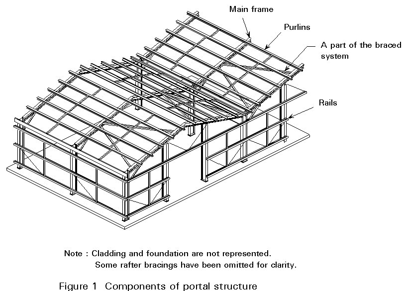
The skeleton of a typical single-storey building is shown in the diagram (Figure 1). It consists of three major elements: cladding for both roof and walls; secondary steel to support the cladding and form framing for doors, windows and the like; and the main frame of the structure, including all necessary bracing. In addition, the building requires foundations which have to be designed and built to transmit all the loads to the soil.

The primary functions of the cladding are to provide shade, shelter, and an attractive appearance. The cladding is therefore arguably the most important element of the structure. It is likely to be some 50% of the total cost even if a fairly basic specification is used. The frame members, both primary and secondary are there to support the cladding and services.
The requirements for walls and roof are somewhat different although both need to be weather tight, durable and provide insulation.
The weathertightness of the roof is clearly paramount, particularly for lower pitches.
In the case of walls the appearance will be the highest priority in making the selection. Cladding formed from metal sheets has emerged as the most popular choice since its introduction in the 1970's. Steel is the most usual substrate with aluminium as a more expensive second choice. The higher coefficient of expansion of aluminium can lead to difficulties in some circumstances.
In the normal single-storey building the cladding is supported on secondary members, which transmit the loads back to main structural steel frames.
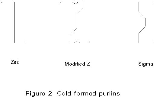
An economic solution is provided by the use of cold-formed light gauge sections [1]. These sections are of proprietary shape and are produced to order on "computer numerically controlled" rolling machines. These processes are extremely efficient since the components are delivered to site pre-engineered to the exact requirements. As a result fabrication and erection times are minimised and material wastage is eliminated. With high volume rolling the material content of purlins and rails is a very significant part of the cost and manufacturers have developed shapes which are extremely material efficient. The most common are zeds, modified Zeds and sigma shapes as shown in Figure 2. Spans are commonly 5-8m but longer spans up to 12m can be achieved.
It is also traditional to use hot-rolled sections as I or C shapes, not so sensitive to the effect of local instability. The centre to centre distance of the portal frames is then reduced, in general, to 5 or 6m.
Generally, the cost breakdown of various elements will be cladding 50%; purlins and rails 10%; mainframe 30%; and foundations 10%. These figures are indicative, as clearly there is considerable variation in specification and cost of the cladding which is the largest single element. Cladding can vary from 10 ecu/m2 to over 150 ecu/m2.
The remainder of this lecture discusses the main frame of the structure. Cladding and secondary elements are considered in Lecture 14.1.2.
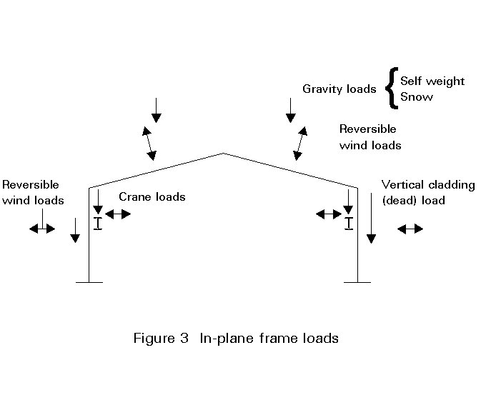
The loads are transferred from the sheeting onto the purlins and rails, which in turn are supported by a primary (or main) structure. These loads can be obtained from the relevant codes. They will include:
When the length of the structure is not too great, say 50 to 100m depending on temperature range, it is normal practice not to consider the effects produced by changes of temperature. It is usual practice, also, not to consider differential settlement of foundations if they are below 2cm.
Wind can of course cause pressure, suction and drag loads on the cladding. Figure 3 illustrates the various components of load to consider in the design.
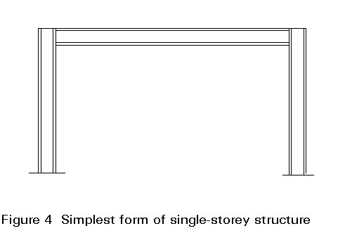
The primary structural frames will normally be spaced from 5 to 8m centres. Although larger spacings are growing in popularity, an analysis of a purlin manufacturers' sales shows that about 6m remains the most popular spacing. The most straight forward single-storey structural form consists of a pair of vertical columns supporting a spanning beam. To be practical, there is a need for a fall in the roof finish to provide adequate drainage. For the small spans for which this arrangement is suitable, the fall can be achieved in the finishes or by a nominal slope in the beam. This form of construction, is shown in Figure 4. Stability against wind loading can be provided by the cladding which is fixed from frame to frame. This simple form of structure is used for small workshops. It is only suitable for spans up to approximately 12m.
For longer spans this simple solution becomes, in general, uneconomic. Then portal frames and lattice trusses are more competitive solutions.
Figure 5 shows some options commonly used for portal frames. The more popular solutions are pinned bases if there is no crane to be supported and the fully rigid version when it is necessary to support crane loads and to obtain smaller horizontal displacements. Less weight of steel results, in any case, from fixed based frames, but the additional cost of the foundations of the supports can be higher than the saving of steel.
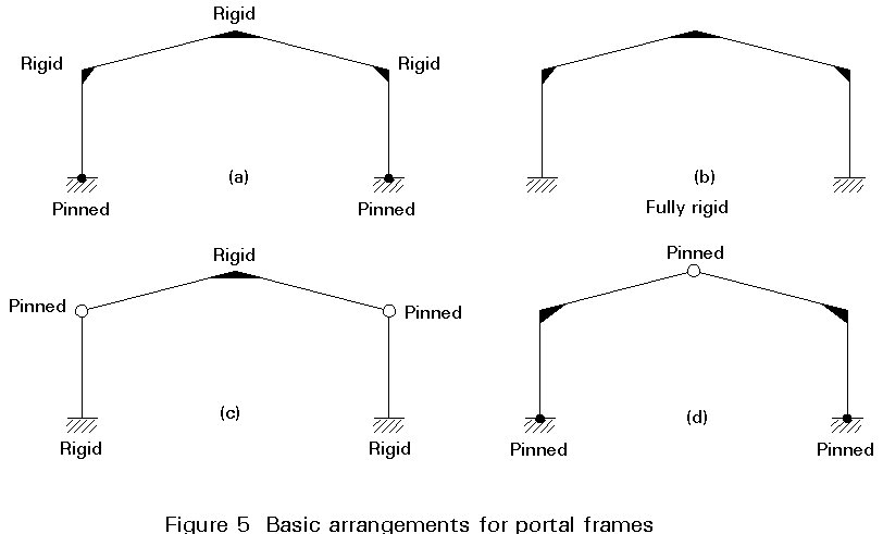
Figure 6 shows an example of solid column with a typical lattice girder.
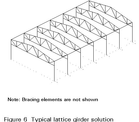
Whichever solution is chosen, all loads have to be transferred to the ground in a coherent fashion in even the simplest of buildings. The provision of bracing is covered in Lecture 14.1.2.
Restraints to the main structure against out-of-plane buckling can be provided by the purlins connected to the top flange of the rafter and by the rails connected to the outer column flange. Figure 7 shows three typical ways of providing adequate restraint.
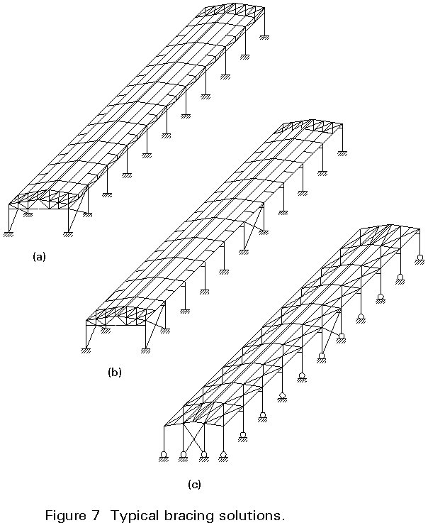
Plastic design of portal frames brings limitations on the spacing of restraints of about 1,8 to 2m. At plastic hinge locations, it is necessary to provide stays from the rail to the inner flange in order to avoid the lateral buckling of the compressed flange. The cladding spans between the purlins and commercially available profiles are economic in this range of spacing to meet the requirements for walkability, strength (corrugation depths), and drainage.
Where lattice structures are used, secondary bending in the top boom is avoided if the purlins are supported at the node points. Spacings of about 1,8m are often found convenient and economic.
It is also possible to use the cladding as a stressed skin in order to transmit the horizontal forces generated in the roof by the wind and the tendency of the frame to out-of-plane buckling.
The cross-section shown in Figure 4 is undoubtedly the simplest framing solution which can be used to provide structural integrity to single-storey buildings. Used predominately in spans of up to 10m, where flat roof construction is acceptable, the frame comprises standard hot-rolled sections having simple or moment-resisting joints.
Flat roofs are notoriously difficult to weatherproof, since deflections of the horizontal cross-beams induce ponding of rainwater on the roof which tends to penetrate the laps of the traditional cladding profiles and, indeed, any weakness of the exterior roofing fabric. To counteract this, either the cross-member is cambered to provide the required fall across the roof, or the cladding itself is laid to a predetermined fall, again facilitating drainage of surface water off the roof.
Due to the need to control excessive deflections, the sections tend to be somewhat heavier than those required for strength purposes alone, particularly if the cross-beam is designed as simply supported. In its simplest form, the cross-beam is designed as spanning between columns. For gravity loadings the latter are in direct compression apart from a small bending moment at the top of the column due to the eccentricity of the beam connection. The cross-beam acts in bending due to the applied gravity loads, the compression flange being restrained either by purlins, which support the roof sheet, or by a proprietary roof deck which may span between the main frames and which must be adequately fastened.
Resistance to lateral loads is achieved by the use of a longitudinal wind girder, usually situated within the depth of the cross-beam. This transmits load from the top of the columns to bracing in the vertical plane, and thence to the foundation. The bracing is generally designed as a pin-jointed frame, in keeping with the simple joints used in the main frame.
Buildings which employ the use of beam-and-column construction often have brickwork cladding in the vertical plane. With careful detailing, the brickwork can be designed to provide the vertical sway bracing, acting in a similar manner to the shear walls of a multi-storey building.
Resistance to lateral loading can also be achieved either by the use of rigid connections at the column/beam joint or by designing the columns as fixed-base cantilevers.
Rigid connections and rigid column/foundation joints reduce also the deflection of the beam and need less weight of structural steel for the frame.
As explained above, the two most popular arrangements are the portal frame with pinned bases, if there is no crane to be supported, and the fully rigid portal frame, which is often used if there is a crane. These forms are both functional and economic. In- plane stability is derived from the provision of moment-resisting connections at the top and at the beam-to-column connections for the first situation and also at the base in the second one [2].
The falls required to the roof are naturally provided by the cladding carried on purlins which, in turn, are supported by the main frame members. Architectural pressures lead to the use of the flattest slopes compatible with weathertightness. The most common slope is about 6°, but slopes as low as 1° have been used.
The frames are constructed from I-section rafters and columns with haunches at the connections at the eaves as illustrated in Figure 1. The haunch length is approximately 10% of the span and can be formed from welded plate or more commonly a cutting from a rolled section. The depth at the column face is typically slightly deeper than the rafter section. The design of these frames is dealt with in Lecture 14.2 and Lecture 14.3. Portal frames can be also built with tapered rather than haunched sections. Frames of this type are common in the USA and are being used more frequently in Europe. The sections are fabricated from plate on automated welding machines. The ability to vary web thickness, flange dimensions and section depth results in high material efficiency. Deep slender sections are used to maximise economy. Suitable design methods are described in Lecture 14.3. In addition to material economies there are benefits in reduced deflections resulting from the high in-plane stiffness of the deep sections.
Portal frames are particularly economic up to 40m spans and, where the internal planning permits, multi-bay configurations of 20-30m spans are effective. They have been used for frames up to 75m span.
Figure 8 shows a typical frame built with lattice trusses. Lattice structures are lighter than the portal alternatives for spans greater than 25m but the additional workmanship increases fabrication costs [3]. Figure 9 gives an indication of the relative material weights. It is not possible to be definitive but based on structural requirements, lattice systems are likely to be cost effective for spans over 50 m.
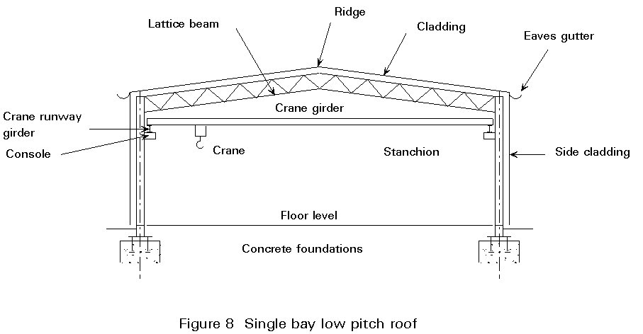
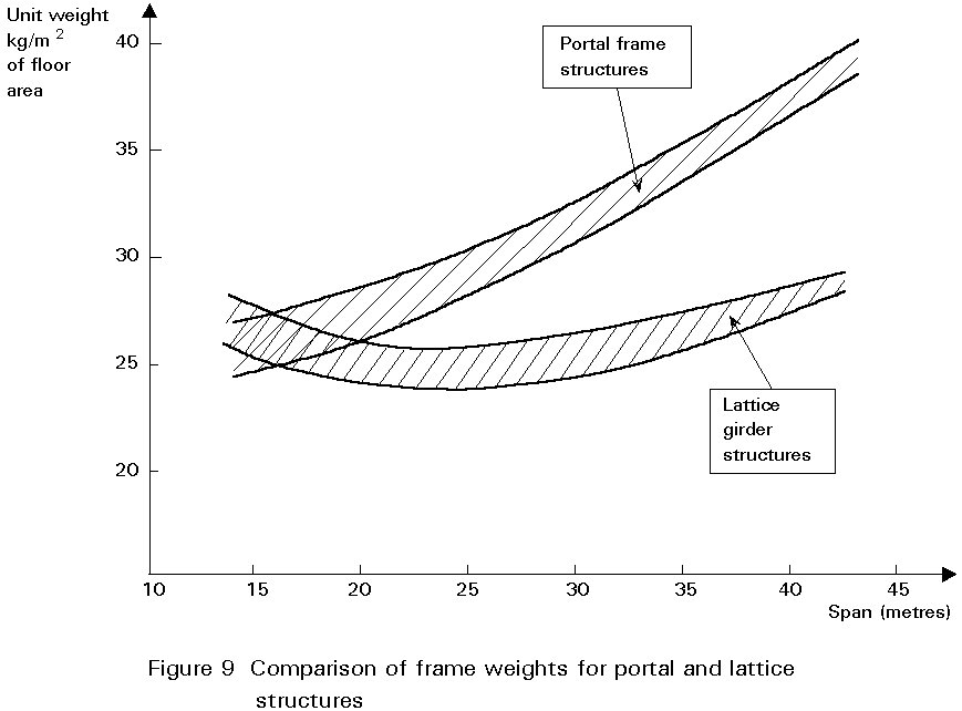
Because lattice girders have a much larger second moment of area and section modulus than a corresponding I section of a similar weight, they have greater stiffness and resistance to load. These enhanced properties are however accompanied by higher fabrication and erection costs due to the required effort for the connections. Spans up to 80m have been realised in that way.
When deciding the size of different elements of the lattice girder, the engineer should be aware that stress reversals are likely due to wind effects.
Frames are normally positioned at 6,0m to 8m centres. These spacings generally provide economic solutions for the cold-formed purlin and side rail arrangements.
Generally a decision is taken early during the process of conceptual design on the type(s) of member(s) to be used for the latticed frame. There are many alternatives:
a. Hollow sections - circular or rectangular.
b. Traditional sections - angles, tees, channels, I sections.
c. Combination of (a) and (b).
The selected truss should reflect not only the design aim to produce the lightest frame but also fabrication and erection requirements.
Examples of composite form are shown in Figure 10 where the booms are I sections and the internal members are RHS. The I sections enable easy connection of services to the truss and easy connection to columns. Bracing in the plane of the roof can be provided using simple in-plane members and simple connections, or by using the relative stiffness of an I or H section.
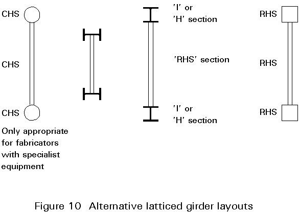
The specific advantages of hollow sections (and tubes) when compared with traditional sections (I sections, channels, angles, etc.) are the high strength to weight ratio, maximum efficiency in tension, efficiency as struts, good torsional properties, appearance and maintenance. In considering use of CHS or RHS the designer should remember that some fabricators are not fully equipped to fabricate circular hollow sections. (Connection costs are considerably reduced if RHS beams are selected, with CHS or RHS web members). The main disadvantages of CHS and RHS are the higher cost of connections at some nodes and the relative difficulties of making on-site connections for services (electrical, etc.). In addition basic costs are higher than traditional sections on a tonnage basis (overall however frames of lighter weight are produced).
The relative slopes of the internal members should be considered in relation to the detailing and fabrication process. If they are parallel to each other then the angle of cut at each end is identical for all members.
The final decision on the type(s) of member(s) to be used may be influenced by aesthetics and not cost.
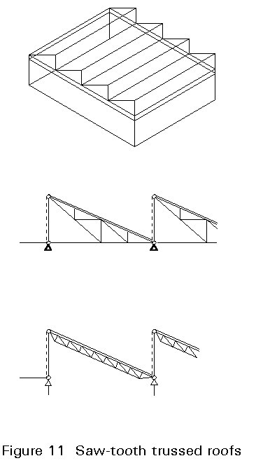
Early industrial buildings were built with saw tooth truss layouts illustrated in Figure 11. The vertical (or nearly vertical) elements were glazed and north facing to allow the maximum daylight with minimum direct sun light. In modern times the need for natural lighting has diminished with modern lighting systems and while 10% of area of roof lighting through translucent panes is common, many take advantage of the more reliable and controllable conditions with no natural lighting at all.
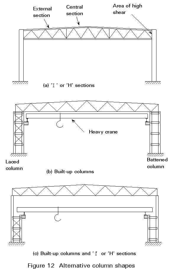
Generally, the columns to the frame are I or H sections (Figure 12a). The latter have a greater transverse stiffness than the former and are preferred in cases of biaxial bending. When the building incorporates an overhead travelling crane of high capacity, a built-up load or battened column may be used (Figure 12b). In some cases the built-up columns are continued by I sections over the level of the crane supporting structure in order to reduce the costs (Figure 12c).
The dominant gravity load is from snow. The general case is the application of a basic uniform load, but with sloping roofs having multiple spans and parapets, the action of drifting snow has to be considered. The basic loading is variable according to location. Design information is currently given in national load codes and will be addressed in Eurocode 1, in due course. The main frame design for portals can be carried out using the uniform load case but the variable loads caused by drifting are to be applied to cladding and purlins. The effects of drifting are idealized into triangular loadings with formulae given for the various effects of valleys, parapets, upstands, etc. Early tests carried out in the UK established that equivalent uniformly distributed loads can be used for the purlins design. In the areas of high local load, consideration has to be given as to whether to reduce purlin spacing or to increase the gauge. Where practicable the reduction of spacing is preferable as it prevents the dangers and disruption involved with identification and production of different thicknesses of purlin supplied to one job.
For portal frames the frame strength will usually be determined by the snow load case, unless the eaves height is large in relation to span.
With lightweight cladding and purlins and rails, wind loads are important. Cladding and its fasteners are designed for the local pressure coefficient, for example as given in BS6399: Part 3 and other national codes. Purlins and main frames are designed using the relevant statistical factors, but not additional local coefficients. Care must be taken to include the total effect of both internal and external pressure coefficients.
Service loads for lighting, etc., are reasonably assumed to be globally 0,6kN/m2. As service requirements have increased, it has become necessary to consider carefully the provision to be made.
Most purlin manufacturers can provide proprietary clips for hanging limited point loads to give flexibility of layout. Where services and sprinklers are required, it is normal to design the purlins for a global service load of 0,1 - 0,2kN/m2 with a reduced value for the main frames to take account of likely spread. Particular items of plant must be treated individually. The specifying engineer should make a realistic assessment of the need as the elements are sensitive and, while the loads may seem low, they represent a significant percentage of the total and affect design economy accordingly.
Where moving loads such as cranes and conveyors are present (Figure 13), in addition to the gravity loads, the effects of acceleration and deceleration have to be taken into account in the design. A quasi-static approach is generally used in which the moving loads are enhanced and treated as static loads in the design. The enhancement factors to be used depend on the particular plant and its acceleration and braking capacity. Manufacturers must be consulted where heavy, high speed or multiple cranes are being used.

To take into account dynamic effects due to cranes, the maximum vertical loads and the horizontal forces are increased by specific factors which can be found in national guidance.
The repeated movement of a crane gives rise to fatigue conditions. Fatigue effects are restricted to the local areas of support, the crane beam itself, support bracket and the connection to main columns. It is not normal to design the whole frame for fatigue as the stress levels due to crane travel are relatively low.
In certain areas, the effects of earthquakes should be considered. In those countries affected, there are maps which identify the seismic level of each zone and standards to evaluate structural behaviour. Eurocode 8 [5] deals specifically with this problem.
In common practice, it is not necessary to take into account differential settlement of less than 2,5cm. If differential settlement exceeds 2,5cm, its effects must be examined, both from the structural and functional points of view. In less ductile structures, such as those constructed with sections not in Class 1 or 2, it is always important to evaluate the sensitivity of the structure in relation to possible differential settlement.
It is also general practice not to take into account the effects of temperature when the maximum dimension of the building is less than 40 to 50m, or when expansion joints have been used which separate the structure into zones which do not exceed this dimension. Elsewhere, it is important to evaluate the effects of variations in temperature. It is also necessary to ensure that the characteristics of the finished structure, both the systems of fastening and the seals in the envelope, are compatible with the inevitable deformations due to change in climate.
Important factors which must be considered at the conceptual and detailing stages are the questions of workshop facilities and space and of transport between workshop and site. Whilst large girders and/or large sections may appear to be desirable in order to reduce the number of site connections, the use of large members can often reduce the number of fabricators who can tender for a given project.
The lengths of members available from stockists or direct from the mill can vary. When long lengths are deemed desirable it is necessary to check their availability. Generally standard sections can be obtained in a reasonable time but there are likely to be delays and additional cost if non-standard sections are required. The use of slightly heavier sections and standardisation of section size may lead to a cheaper fabricated structure. When large prefabricated trusses are used it may be necessary to provide lifting points (eyes) which are located to minimise stresses induced during lifting. All parts which are shop painted need to be handled carefully to avoid damaging the coating.
Latticed girders are made up of long, basically slender members, and may therefore be subject to severe distortion due to welding unless care is taken during the fabrication process.
It is essential that the design engineer notes that:
i. bulk orders of minimum size variation are cheaper than small orders of many different sizes.
ii. the number of pieces to be handled should be kept to a minimum.
iii. weld distortion and tolerances should be allowed for.
iv. automated fabrication is generally cheaper.
v. careful design can minimise transportation costs.
vi. specifications need to be realistic to reduce costs.
vii. good quality control is essential.
In each country there are specific lengths and widths of structures that may be transported without any problems, e.g. widths up to approximately 3 m, lengths up to 15m. For larger dimensions a police notification or special permission is required.
It should be noted that the various police authorities specify different periods when abnormal loads are allowed to move through their districts. If neighbouring "times" are significantly out of phase and general traffic hold-ups cause disruption to the movement of abnormal loads, it is possible for loads to be delayed by up to 24 hours. If one or more cranes and associated erection staff are unable to work because of these enforced delays, the additional costs can be very significant. Some towns and cities place length restrictions on materials which can be moved by road.
Girders can be fabricated and despatched lying flat. The overall height allowed for the load is dependent upon the route travelled and the clear height of any bridges likely to be encountered. Rail transport can accommodate long pieces, but width and height are more restricted.
To limit the length of units being transported, trusses may be divided into welded parts (2, 3 or more parts) which may be bolted together on site. The complete rafter can be then craned into position.
For export where shipment is involved, pieces up to the same dimensions as for road transport may be accommodated. It should be appreciated, however, that shipping charges are often based on volume rather than weight. There are often relatively severe restrictions on the length of a piece that can be carried in the hold of a ship. The ship's engineer may refuse to carry steelwork as deck cargo. It may be found more economical to despatch the steel in pieces for subsequent assembly on site.
In considering the erection of a framework, the designer seeks an economic but safe process. The cost of erection can be a significant proportion of the cost of a steelwork contract. It is often useful for a designer with little or no experience of steel erection to discuss possible solutions with a contractor. The latter will know how to build and avoid the possibility of collapse and how to satisfy the insurer. Potentially steelwork erection is hazardous and good control is required to ensure safety of the erectors.
Latticed girders can conveniently be assembled on the ground and lifted into place. However, since cranes are likely to be used, the effect of dynamic lifting loads or stress reversals should not be ignored. All steel structures are likely to require temporary bracing, which may be part of the permanent system. The temporary systems need to be carefully designed. The following points summarise the process:
a. Structural steelwork erection is an operation requiring meticulous planning from conception to completion.
b. The operation involves many disciplines and requires co-operation and communication between all those involved.
c. It is an operation which is dependent upon the personal competencies of all those involved to ensure the contract is completed without accident, on time and within the budget.
[1] Davis, J. M. and Raven, G. K., 'Design of Cold Formed Steel Purlins', IABSE Thin Walled Metal Structures in Buildings Colloquium, Stockholm 1986.
[2] Dowling, P. J. et al, 'A Development in the Automated Design and Fabrication of Portal Framed Industrial Buildings', Institution of Structural Engineers, London, October 1982.
[3] Horridge, J. F. and Morris, L. J., 'Comparative Costs of Single Storey Steel-Framed Structures', Institution of Structural Engineers, London, July 1986.
[1] Ballio, G. and Mazzolani, F. M., 'Theory and Design of Steel Structures', Chapman and Hall, 1983.
[2] Eurocode 3: "Design of Steel Structures": ENV 1993-1-1: Part 1, General rules and rules for buildings, CEN 1992.
[3] Dowling, P. J., Knowles, P. R., and Owen, S. G. W., "Structural Steel Design", Butterworths, 1988.
[4] Steel Designers' Manual, fifth edition. The Steel Construction Institute, 1992.
[5] Eurocode 8: "Structures in Seismic Regions - Design", CEN (in preparation).