ESDEP WG 14
STRUCTURAL SYSTEMS: BUILDINGS
To describe further the functions and characteristics of the cladding and the elements of the secondary structure in single-storey buildings and to give guidance of purlin/wind designs.
None.
Lecture 1B.5.1: Introduction to Design of Simple Industrial Buildings
Lectures 9: Thin-Walled Construction
Lecture 14.2: Analysis of Portal Frames: Introduction and Elastic Analysis
Lecture 14.3: Analysis of Portal Frames: Plastic Analysis
Lecture 14.4: Crane Runway Girders
The functions and characteristics of the elements of the envelope and secondary structure of single storey buildings are described. The derivation of the load-carrying resistance of cladding using manufacturers' tables is presented and the design of purlins using manufacturers information is outlined.
Finally the requirements for main frame bracing are discussed.
Lecture 14.1.1 provided a brief outline of the functions of the various elements of single-storey buildings. Design methods for frames of the various configurations are presented in other lectures and are also described in conventional text books. The derivation of design and selection of commercially available cladding, purlin and rail systems are not generally covered elsewhere.
The lecture reviews the available systems and selection criteria. It concludes with a description of bracing systems used in single-storey buildings.
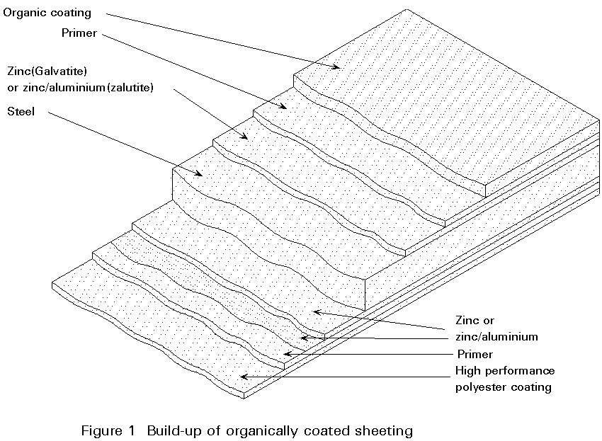
Steel-based cladding sheets are formed from a substrate with layers of galvanising, primer and colour coating as indicated in Figure 1. For the weather face the coating will normally be polyvinyl chloride (PVC), polyvinyl fluoride (PVF2) or, where price is a constraint, the less durable acrylic coatings. PVC and PVF2 can be expected to have a life to first maintenance of 10 to 25 years depending on environmental conditions. Light colours should be used on roofs to minimise heat absorption and thermal movement. PVC should not be used in latitudes less than 49° [1].
There are four main categories of cladding system:
Where double skin systems are used the liner sheet, normally as thin as 0,4mm, has a similar coating build-up but with a light coloured polyester paint to the inner face. In addition to providing weather protection the cladding provides insulation to the building. The thickness varies according to the insulation required with typical values of 0,45 w/m2° C being obtained from 80mm of fibreglass or mineral wool. The equivalent in composite panels would normally be obtained from 50mm thickness. Manufacturer's literature should be considered for particular cases.
The characteristics of the various roof systems are:
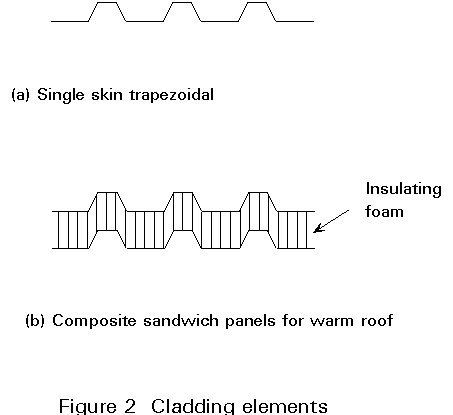
Single Skin Trapezoidal Roofing
This is the most basic form of cladding construction. The main problem is to prevent condensation since it is difficult to exclude damp air from the underside of the sheeting. The internal appearance is utilitarian since the insulation usually takes the form of unrolled thermal quilting supported on wire mesh or rigid boards supported on T Bars.
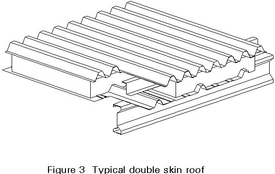
Double Trapezoidal Shell Roof Construction
This is the most common form of cladding both for walls and roofs, with pitches down to approximately 5°. It consists of a steel liner sheet fastened to the purlins or rails with an outer weather sheet held apart by Zed spacers. The gap created contains insulation normally of fibreglass or mineral fibre. Sealing of the liner skin or addition of a vapour barrier and breather membrane can be employed to improve performance in situations where there is a higher condensation risk. Manufacturers normally supply a co-ordinated range of accessories and rooflights to match their particular profiles.
A typical construction is shown in Figure 3.
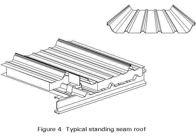
Standing Seam and Concealed Fix Roofs
As steel has replaced asbestos cement in sheeting, lower roof slopes have become possible and the appearance of buildings has greatly improved, both in form and colour treatment.
It is feasible to disguise the sloping roofs and provide the rectangular appearance recently favoured by planners, engineers and architects who have become increasingly involved in this type of building. The problems associated with drifted snow and internal gutters, together with the wasted heated in the space in a sloping roof encouraged the development of systems which remain weathertight at slopes down to 1°. These developments have been achieved by minimising laps and through fasteners. The current range of standing seam and concealed fastener systems are provided in long lengths, up to 32m with special transport arrangements, and use of clips to hold the sheeting down to the purlins. Typical construction is shown in Figure 4.
The outer sheeting is used to provide the weather skin in both single and double construction, as previously described.
Composite or Sandwich Panels
This is the most recently developed form of cladding and consists of panels where the insulating foam is integral with the two metal skins [2]. The foam, which during manufacture is pumped into the space between the skins, expands to totally fill the void and adheres to both liner and outer sheet (Figure 2b). This composite action gives robust stiff panels, with the further benefit of rapid erection since the whole skin is fastened in one operation.
Composite panels are available with traditional type trapezoidal outer skins and through fasteners, while more recent developments include standing seam variations allowing slopes down to 1°.
The systems used for walls are similar in construction to those for roofing. Since the sheets will normally be vertical the weatherproofing requirements are less rigorous. Another important difference compared to roofs is the lower angle of incidence of the sun allowing the full range of colours to be used without excessive surface temperatures, so giving the architect the widest possible scope for creative use of colour.
Given appropriate attention to joint detailing, wall cladding can be fixed horizontally, diagonally or in combinations.
The range of construction includes, as for roofs, single skin, double skin and composite systems, with both conventional and secret fastenings. Appearance is a major consideration in the selection of the particular type to be used.
All reputable manufacturers supply brochures giving details of the systems offered. General advice can be obtained from literature.
Non-composite Systems
Since the sheets are rolled formed, the designer has to select the profiles from the various manufacturers pre-determined shapes. The sheets must be strong enough to resist the various loads which will be applied in construction and during service without damage or excessive deflection. For simple profiles, calculation methods are available in some national codes and European recommendations. Most manufacturers carry out full scale tests to determine the strength of their various profiles.
The test regimes for steel sheeting are designed to take account of the various limiting criteria. The criteria relate to shear of the webs combined with bending at internal supports for shorter spans and mid-span bending for longer, simple spans. Sheets are therefore tested with jacking loads and spreader beams, air bags or vacuum boxes with spans representative of the shortest and longest support spans anticipated in practice. The maximum allowable shears and moments are derived together with deflection behaviour and load tables for service conditions drawn up for pressure and suction conditions.
One important facet of a roof sheet is its ability to withstand local point loads both to sustain personnel walking on it during construction and also in service for maintenance purposes. It is this aspect which governs the minimum thickness acceptable for a roof sheet. This thickness is between 0,6 and 0,7mm. Current approval regimes include a point load test. Sheeting which passes this test will be suitably robust for construction loads but care needs to be taken with walking on PVF2 and painted finishes.
Wall cladding is often 0,5mm thick. To allow selection of the appropriate profile and thickness the majority of profilers (manufacturers) publish catalogues containing suggested fixing and sealing details together with allowable loads for the range of span conditions for both pressure and suction actions.
In addition to resisting externally applied loads, conventional cladding with screw fasteners can provide lateral restraint to the purlins and side rails supporting it. In this application care should be taken in the specification of the fasteners concerning prevention of corrosion around the connections. Standing seam or concealed fastener systems have clips which hold the sheets down but allow expansion and contraction of the sheets and so provide a lower restraint value to the rails. Where these systems are used it is necessary to provide supplementary restraints to the purlins. At present there is no generally accepted guidance on the amount of restraint provided by these newer forms of cladding. Advice on the necessary inclusion of additional restraint in the form of sag bars is available from rail manufacturers relating to their particular products.
Where a metal liner tray is used in conjunction with a cladding system fixed by clips, adequate rail restraint is normally provided if the tray is fastened in the conventional manner.
Composite Systems
The use of foam filled panels has become more common over the past few years. They are more complicated to evaluate in design since the properties of the foam and its adhesion to the two metal skins are fundamental to the performance of the panels. In addition to the normal applied loads, the inherent insulating qualities of the panels leads to significant temperature gradients which have to be taken into account in the panel design.
Calculation methods for analysis are available but the shapes of practical panels are outside of their current scope. It is normal therefore for extensive testing to be carried out by manufacturers in order to obtain type approval from the appropriate national authorities. The tests, in addition to normal load tests, include thermal cycling on full scale panels and foam evaluation to ensure the essential adhesion to the skins is obtained. Quality assurance regimes are an essential part of the manufacturing process. The results of the tests are collated and simplified to produce load carrying tables.
Although some long-span cladding systems are available which will span up to 6m, most portal frame structures are designed with purlins and rails supporting the cladding and spanning between the main frames.
The spans between frames are between 4,5 and 10m with 6 to 7,5m being most popular. Roof decks of larger span are used primarily in flat roof systems and are supported directly on the trusses.
The purlins can be designed as continuous beams supported by three or more portal frames. Because of the difference in the value of the support reactions, it is necessary to stagger the joints to obtain equal loads on the main frames.
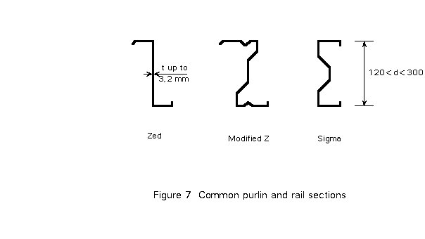
The purlins and rails are commonly supplied by specialist manufacturers who deliver pre-cut and punched cold-rolled items together with the necessary sag bars, cleats or rafter stays. Material economy is vitally important to the manufacturers whose output is often in excess of 80km/week. They have therefore developed and refined by testing a variety of shapes. The more common ones are Zeds, modified Zeds and Sigma shapes illustrated in Figure 7.
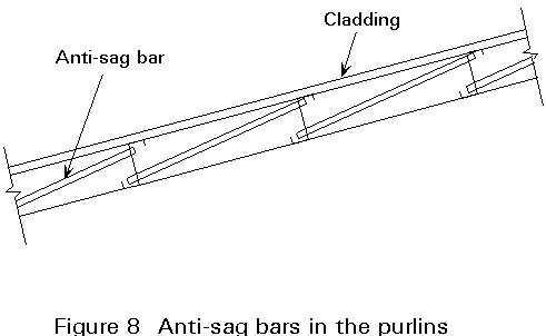
Depending on the slope, anti-sag bars may be necessary to provide one or two intermediate supports in the direction of the weak axis of the beam (Figure 8). Generally, the anti-sag bars are connected using diagonal ties to the portal frames to avoid an increase of the load in the purlins at the top.
Zeds
The Zed section was the first shape to be introduced. It is material efficient but its major disadvantage is that the principal axes are inclined to the web and so out-of-plane forces are generated. When asbestos covered roofs with slopes of the order of 10° were normal these forces were advantageous and opposed to the down slope forces.
Modified Zeds
As lower roof pitches have been introduced, modified Zeds have been developed with the inclination of the principal axis considerably reduced, so enhancing overall performance. Stiffening has also been introduced, improving material efficiency.
These more complicated shapes have to be produced by rolling rather than by press braking.
Sigma Shape
The first shapes to be employed were the simple Zed and Channel since they could be formed by press brakes. As described above the Zed shape has been modified to overcome its major disadvantage. The Channel has not achieved much use, since, although its principal axes are parallel to the major elements, the shear centre lies well outside of the section. Undue twisting under load results which can be reduced by shaping the web and creating a sigma shape such that the shear centre is approximately coincident with the load application line. One manufacturer now produces an economical second generation product of this configuration using rolling techniques.
Classical I-beams such as IPE I CDN or HE can also be used as purlins. I-beams and channel shapes can be used as rails. These shapes are less sensitive than the previous ones to the effect of local instabilities and there is preferences to use them in some countries. However, cold-formed sections are generally the most economical solution.
Cold-formed sections manufactured from thin gauge material are particularly prone to twisting and buckling due to factors which are directly related to the section's shape. The torsional constant of all thin gauge sections is low due to it being a function of the cube of the thickness; in the case of lipped channels the shear centre is eccentric to the point of application of load thus inducing a twist on the section; in the case of zeds the principal axes are inclined to the plane of the web thus inducing bi-axial bending effects. Clearly the above secondary effects, induced by the primary load application, affect the load-carrying resistance of the section.
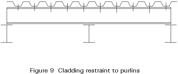
When used in service the support system is subject to downward loading due to dead and live loads arising from the weight of the cladding, snow, services, etc., and uplift if the design wind pressure is greater than the dead load of the system. Therefore, for a typical double span system as shown in Figure 9, most of the compression flange is directly restrained laterally and against rotation by the cladding for downward loading, but it is not so restrained in the case of load reversal.
In supporting the external fabric of the building, the purlins and side rails gain some degree of restraint against twisting and rotation from the cladding and the method of its fastening to the supporting members. In addition, the connection of the support members to the main frame also has a significant effect on the load-carrying resistance of the section. Economical design, therefore, must take account of the above effects.
Several approaches are used for the design of purlin and rail systems.
a. Design by calculation based on an elastic analysis as detailed in the relevant codes of practice. This approach neglects any beneficial effect of cladding restraint for the uplift case and in the compression zone adjacent to the central support in double span arrangements. It is normally confined to "one-off" situations where material savings do not justify more rigorous solutions.
b. Design by calculation based on a rational analysis which accounts for the stabilising influence of the cladding, plasticity in the purlin as the ultimate load is approached and the behaviour of the cleat at the internal support. The effects, however, are difficult to quantify. Although understanding of the restraint of purlins by cladding is improving and methods for including the cladding/purlin interaction are available, the methods are necessarily conservative. They are included in Eurocode 3: Part 1.3 [4] but are likely to be used in the short term only by small to medium volume users where potential material savings do not justify a major test programme.
In some countries, despite the almost traditional nature of these forms of construction, it is not permitted to take account of cladding restraint to the purlins in the section design if the cladding is to be supplied and fixed by differing suppliers. This restriction is due more to the apportionment of responsibility should there be failures than due to lack of technical knowledge. This situation is unusual since a great deal of construction depends on the interaction of elements supplied and fixed by different contractors.
c. Design on the basis of full-scale testing
Manufacturers differ in the design methods they use. The methods are based on the observed behaviour of the system under test.
For volume production, design by testing is the approach which is normally used. Although this approach is expensive, maximum economy of material can be achieved and the cost of the testing can be spread over several years of production.
Design by testing involves the "fine-tuning" of theoretical expressions for the collapse load of the system.
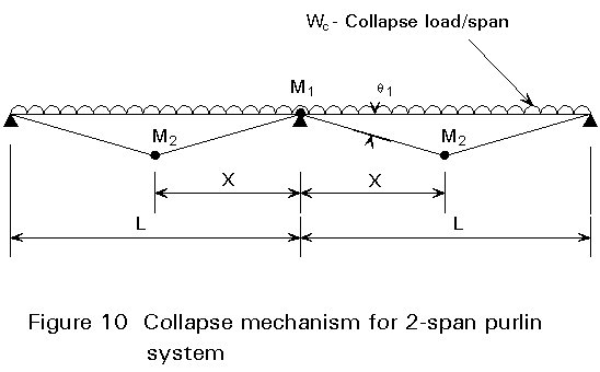
For example, although the sections involved are inevitably slender, the collapse mechanism which occurs with a well developed two-span system is essentially as represented in Figure 10. The published paper [3] on one manufacturer's system shows that the collapse load will be:
Wc = f (M1, M2, x, L)
with
x = f (M1, M2, L)
and
qp = f (Wc, M1, L)
The performance of a two-span system is considerably enhanced if some redistribution of bending moment from the internal support is taken into account. The moment-rotation characteristic at the support depends very much on the cleat detail and the section shape. The characteristics of the central support can be found by testing a simply supported beam subject to a central point load applied through a cleat so as to simulate the behaviour of the central support of a double span system.
From this test, the load-deflection characteristics can be plotted well beyond the deflection at which first yield occurs. A lower bound empirical expression can then be found for the support moment, M1, based on an upper limit of rotational capacity. A similar expression can be found for M2, the internal span moment, again on the basis of a test on a simply supported beam subject to a uniformly distributed load, applied by the use of a vacuum rig, or perhaps sand bags.
The design expressions can then be confirmed by the execution of numerous full-scale tests.
The results of the full-scale tests are then condensed into easy to use load span tables which are detailed in the purlin manufacturers' design and detail literature.
The tabular format is typical of that contained in purlin manufacturers' technical literature. The table is generally prefaced by explanatory notes regarding fixing condition and lateral restraint requirements, the latter being particularly relevant where load reversal occurs. Conditions which arise in practice, and which are not covered in the technical literature are best dealt with by the manufacturer's Technical Service Department, which should be consulted for all non-standard cases. Anti-sag bars are used on longer spans to assist erection and improve performance under wind suction.
Side rail design is essentially identical to that for purlins, and load resistances are again arrived at via test procedures.
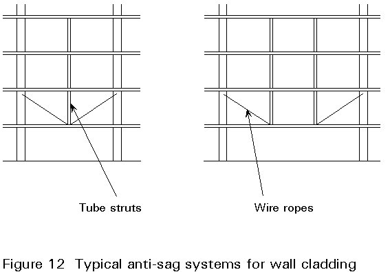
The practical construction problem of levelling side rails in the field, to remove self weight deflection about the weak axis of the section, is overcome by the use of a tensioned wire system incorporating the use of tube struts, typically at mid-span for spans of 6 - 7m, and third-points of the span for spans of 7 - 8m and above. Typical methods are shown in Figure 12.
Returning to the requirements for the main frame which were discussed in Lecture 14.1.1, most frame configurations for larger spans have moment resisting joints at the column/roof member connections. In addition to assisting with deflection control and reducing member sizes, this arrangement provides inherent resistance to lateral in-plane loads such as those from side winds and crane movements.
Bracing, both horizontal and vertical, must be provided to transfer to the foundations the horizontal loads due to wind possibly earthquake and out-of-plane loads.
It is possible to use the cladding and wall panels instead of braces for this purpose. In that case stressed skin design should be used (Lecture 9.5).
When masonry is used as all or part of the vertical cladding, it is feasible to use that element as part of the bracing system.
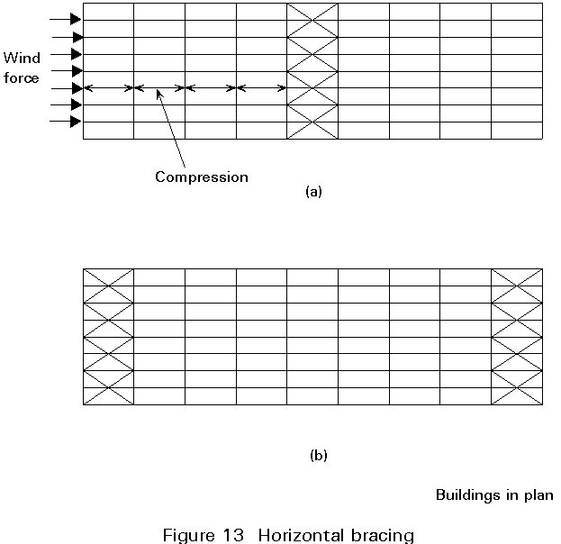
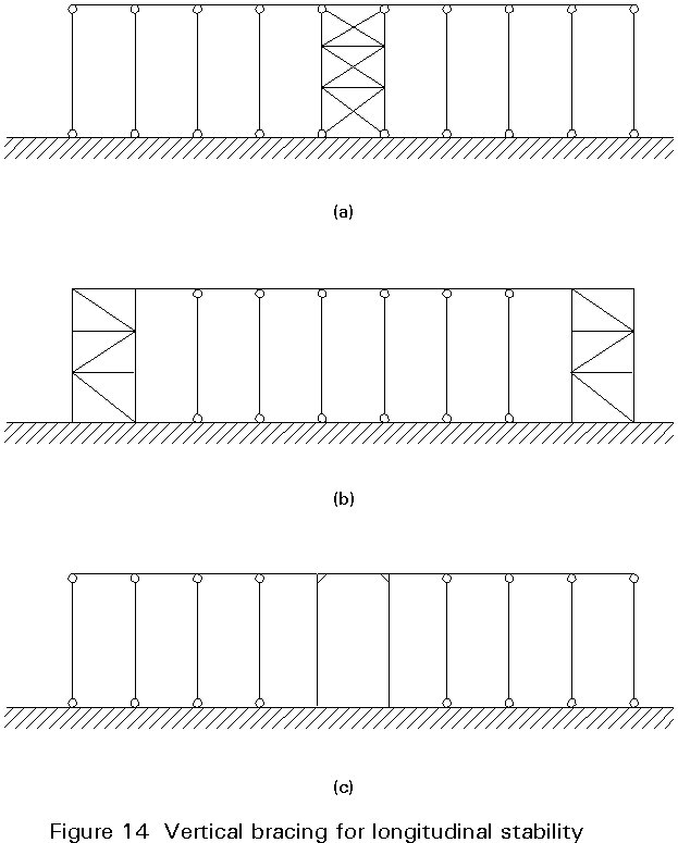
The bracing can be single diagonals or cross members. If the former system is adopted, the members are designed to support compressive and tensile loads. When cross members are used only the members in tension are assumed to be effective, those in compression being designed to satisfy the slenderness criteria.
Bracing may be located either at mid-length of the building (Figures 13a, 14a, and 14c) or at its ends (Figures 13b, and 14b). Bracing at the ends helps for erection purposes, since it provides a stable structure at one end of the building when the erection starts. Its disadvantage is that it prohibits the free movement of the building due to temperature so that stresses in the members, sometimes of considerable amount, may result. By putting the braces at the mid-length this disadvantage disappears since the building is able to expand freely. However additional temporary braces should be provided during the erection stage to stabilise the first part of the building. The horizontal forces have to "travel" from their point of application in the gable to the brace thus causing compression in the purlins.
[1] Colourcoat in Building, British Steel Strip Products, Newport, Wales.
[2] ECCS Recommendations for Sandwich Panels: Part 1 Design, Part 2 Good Practice.
[3] Davies, J. M. and Raven G. K., 'Design of Cold Formed Steel Purlins', IABSE "Thin Walled Metal Structures in Buildings" Colloquium, Stockholm 1986.
[4] Eurocode 3: "Design of Steel Structures" Part 1.3, Cold Formed Thin Gauge Members and Sheeting, CEN (in preparation).
|
PANELS Wind loads in kN/m2 WIND |
||||||||||
|
Deflection limit |
Span condition |
Thickness of profile (mm) |
Span 'L' (in metres) |
|||||||
|
1,6 |
1,8 |
2,0 |
2,2 |
2,4 |
2,6 |
2,8 |
3,0 |
|||
|
L/90 |
|
0,5 |
3,00 |
2,30 |
1,66 |
1,24 |
0,94 |
0,73 |
0,58 |
0,46 |
|
0,55 |
3,47 |
2,60 |
1,88 |
1,40 |
1,07 |
0,83 |
0,66 |
0,52 |
||
|
0,6 |
3,96 |
2,91 |
2,11 |
1,57 |
1,20 |
0,93 |
0,73 |
0,59 |
||
|
0,7 |
4,98 |
3,61 |
2,61 |
1,95 |
1,49 |
1,16 |
0,91 |
0,73 |
||
|
0,8 |
6,02 |
4,21 |
3,05 |
2,27 |
1,73 |
1,35 |
1,06 |
0,85 |
||
|
|
0,5 |
2,70 |
2,19 |
1,81 |
1,52 |
1,30 |
1,12 |
0,97 |
0,85 |
|
|
0,55 |
2,94 |
2,41 |
2,01 |
1,71 |
1,46 |
1,27 |
1,11 |
0,97 |
||
|
0,6 |
3,61 |
2,93 |
2,43 |
2,04 |
1,74 |
1,50 |
1,30 |
1,14 |
||
|
0,7 |
4,55 |
3,68 |
3,05 |
2,56 |
2,17 |
1,87 |
1,62 |
1,42 |
||
|
0,8 |
5,14 |
4,20 |
3,49 |
2,95 |
2,51 |
2,17 |
1,90 |
1,66 |
||
|
|
0,5 |
3,28 |
2,67 |
2,22 |
1,87 |
1,60 |
1,39 |
1,14 |
0,91 |
|
|
0,55 |
3,54 |
2,92 |
2,45 |
2,09 |
1,80 |
1,56 |
1,29 |
1,04 |
||
|
0,6 |
4,41 |
3,58 |
2,97 |
2,51 |
2,14 |
1,81 |
1,44 |
1,16 |
||
|
0,7 |
5,56 |
4,52 |
3,74 |
3,15 |
2,68 |
2,25 |
1,79 |
1,44 |
||
|
0,8 |
6,24 |
5,11 |
4,26 |
3,61 |
3,08 |
2,62 |
2,08 |
1,68 |
||
|
L/150 |
|
0,5 |
1,96 |
1,36 |
0,98 |
0,73 |
0,55 |
0,42 |
0,33 |
0,26 |
|
0,55 |
2,22 |
1,54 |
1,11 |
0,82 |
0,62 |
0,48 |
0,37 |
0,29 |
||
|
0,6 |
2,48 |
1,73 |
1,24 |
0,92 |
0,70 |
0,54 |
0,42 |
0,33 |
||
|
0,7 |
3,07 |
2,14 |
1,54 |
1,14 |
0,87 |
0,67 |
0,52 |
0,41 |
||
|
0,8 |
3,58 |
2,49 |
1,80 |
1,33 |
1,01 |
0,78 |
0,61 |
0,48 |
||
|
|
0,5 |
2,70 |
2,18 |
1,81 |
1,52 |
1,30 |
1,08 |
0,86 |
0,69 |
|
|
0,55 |
2,94 |
2,41 |
2,01 |
1,71 |
1,46 |
1,22 |
0,97 |
0,78 |
||
|
0,6 |
3,61 |
2,94 |
2,42 |
2,04 |
1,74 |
1,37 |
1,08 |
0,87 |
||
|
0,7 |
4,55 |
3,68 |
3,05 |
2,56 |
2,18 |
1,70 |
1,35 |
1,08 |
||
|
0,8 |
5,14 |
4,20 |
3,49 |
2,95 |
2,51 |
1,98 |
1,57 |
1,26 |
||
|
|
0,5 |
3,28 |
2,62 |
1,90 |
1,42 |
1,08 |
0,84 |
0,66 |
0,53 |
|
|
0,55 |
3,54 |
2,92 |
2,15 |
1,60 |
1,22 |
0,95 |
0,75 |
0,60 |
||
|
0,6 |
4,41 |
3,32 |
2,40 |
1,79 |
1,37 |
1,06 |
0,84 |
0,67 |
||
|
0,7 |
5,56 |
4,11 |
2,98 |
2,22 |
1,70 |
1,32 |
1,05 |
0,84 |
||
|
0,8 |
6,24 |
4,79 |
3,47 |
2,59 |
1,98 |
1,54 |
1,22 |
0,98 |
||
|
Figures shown in bolder type are limited by deflection. All other loads are limited by stress. |
||||||||||
|
|
||||||||||
ROOF PANELS
Maximum loads in kN/m2 deflection limit L/100
|
PANEL THICKNESS (mm) |
SPAN CONDITION |
FACING DETAILS |
SPAN 'L'(m) |
||||||
|
MATERIAL |
THICKNESS (mm) |
||||||||
|
Outer |
Inner |
1,6 |
1,8 |
2,0 |
2,5 |
3,0 |
|||
|
37 |
|
STEEL |
0,5 |
0,4 |
+ 2,54 - 3,02 |
2,16 2,59 |
1,85 2,25 |
1,28 1,63 |
0,76 1,22 |
|
0,6 |
0,4 |
+ 2,80 - 3,30 |
2,39 2,85 |
2,06 2,48 |
1,42 1,82 |
0,82 1,36 |
|||
|
ALUMINIUM |
0,7 |
0,5 |
+ 2,32 - 2,70 |
1,66 2,26 |
1,21 1,74 |
- - |
- - |
||
|
|
STEEL |
0,5 |
0,4 |
+ 2,54 -3,02 |
2,16 2,56 |
1,85 2,21 |
1,30 1,63 |
0,94 1,22 |
|
|
0,6 |
0,4 |
+ 2,80 - 3,30 |
2,39 2,85 |
2,06 2,48 |
1,46 1,82 |
1,06 1,36 |
|||
|
ALUMINIUM |
0,7 |
0,5 |
+ 2,34 - 2,64 |
1,93 2,25 |
1,62 1,91 |
1,08 1,32 |
0,76 0,96 |
||
|
|
STEEL |
0,5 |
0,4 |
+ 2,54 - 3,02 |
2,16 2,59 |
1,85 2,25 |
1,30 1,63 |
0,94 1,22 |
|
|
0,6 |
0,4 |
+ 2,80 - 3,30 |
2,39 2,85 |
2,06 2,48 |
1,46 1,82 |
1,06 1,36 |
|||
|
ALUMINIUM |
0,7 |
0,5 |
+ 2,34 - 2,70 |
1,93 2,26 |
1,62 1,91 |
1,08 1,32 |
0,76 0,96 |
||
|
60 |
|
STEEL |
0,5 |
0,4 |
+ 3,91 - 4,55 |
3,40 3,97 |
2,98 3,52 |
2,17 2,63 |
1,59 1,99 |
|
0,6 |
0,4 |
+ 4,01 - 4,65 |
3,48 4,05 |
3,07 3,58 |
2,38 2,79 |
1,69 2,23 |
|||
|
ALUMINIUM |
0,7 |
0,5 |
+ 3,85 - 4,33 |
3,23 3,75 |
2,51 3,20 |
1,38 2,00 |
0,78 1,20 |
||
|
|
STEEL |
0,5 |
0,4 |
+ 3,20 - 3,37 |
2,68 2,86 |
2,29 2,49 |
1,65 1,86 |
1,24 1,47 |
|
|
0,6 |
0,4 |
+ 3,70 - 3,88 |
3,10 3,30 |
2,65 2,86 |
1,90 2,13 |
1,44 1,68 |
|||
|
ALUMINIUM |
0,7 |
0,5 |
+ 2,91 - 3,00 |
2,44 2,56 |
2,08 2,23 |
1,48 1,68 |
1,11 1,34 |
||
|
|
STEEL |
0,5 |
0,4 |
+ 3,62 - 3,90 |
3,07 3,35 |
2,64 2,93 |
1,93 2,23 |
1,47 1,78 |
|
|
0,6 |
0,4 |
+ 4,01 - 4,47 |
3,48 3,84 |
3,04 3,35 |
2,22 2,54 |
1,70 2,02 |
|||
|
ALUMINIUM |
0,7 |
0,5 |
+ 3,42 - 3,68 |
2,89 3,17 |
2,49 2,78 |
1,81 2,11 |
1,36 1,68 |
||
WALL PANELS
Maximum loads in kN/m2 deflection limit L/100 L/100
|
PANEL THICKNESS (mm) |
SPAN CONDITION |
FACING DETAILS |
SPAN 'L'(m) |
||||||
|
MATERIAL |
THICKNESS (mm) |
||||||||
|
Outer |
Inner |
1,5 |
2,0 |
2,5 |
3,0 |
3,5 |
|||
|
37 |
|
STEEL |
0,5 |
0,4 |
+ 2,78 - 2,78 |
1,69 1,97 |
0,96 1,06 |
- - |
- - |
|
|
STEEL |
0,5 |
0,4 |
+ 2,78 - 2,78 |
2,09 2,09 |
1,67 1,67 |
1,26 1,39 |
0,90 1,08 |
|
|
|
STEEL |
0,5 |
0,4 |
+ 2,78 - 2,78 |
2,09 2,09 |
1,66 1,67 |
1,11 1,38 |
0,78 0,94 |
|
|
60 |
|
STEEL |
0,5 |
0,4 |
+ 3,40 -3,40 |
2,55 2,55 |
1,81 2,04 |
1,18 1,39 |
0,79 0,91 |
|
|
STEEL |
0,5 |
0,4 |
+ 3,40 - 3,40 |
2,55 2,55 |
2,04 2,04 |
1,70 1,70 |
1,33 1,33 |
|
|
|
STEEL |
0,5 |
0,4 |
+ 3,40 - 3,40 |
2,55 2,55 |
2,04 2,04 |
1,70 1,70 |
1,33 1,33 |
|
Notes to Load Tables
ULTIMATE LOAD TABLES
INTRODUCTION
The following load tables have been prepared to assist the designer in specifying cold formed sections.
The tabulated values are only valid for use with the fixing details and recommendations proposed by the manufacturer.
This information has been prepared as a supplement to the main handbook for ease of reference in the design office.
USE OF TABLES
Note: These values are typical and should not be used in design.
LOAD FACTORS
|
Loading |
Factor |
|
Dead load |
1,4 |
|
Dead load restraining uplift or overturning |
1,0 |
|
Dead load acting with wind and imposed loads combined |
1,2 |
|
Imposed load |
1,6 |
|
Imposed load acting with wind load |
1,2 |
|
Wind load |
1,4 |
|
Wind load acting with imposed load |
1,2 |
|
Forces due to temperature |
1,2 |
PURLINS
|
Span (m) |
Section |
UDL |
Deflection L/200 |
|
4,5
|
B120/150 |
11,89 |
7,77 |
|
A140/155 |
15,35 |
13,67 |
|
|
A140/165 |
17,16 |
14,56 |
|
|
*A140/180 |
19,85 |
15,89 |
|
|
A170/160 |
20,40 |
20,40 |
|
|
A170/170 |
22,70 |
22,70 |
|
|
*A170/180 |
24,97 |
24,97 |
|
|
5,0
|
B120/150 |
10,79 |
6,29 |
|
A140/155 |
13,99 |
11,07 |
|
|
A140/165 |
15,62 |
11,79 |
|
|
*A140/180 |
18,04 |
12,87 |
|
|
A170/160 |
18,63 |
18,02 |
|
|
A170/170 |
20,71 |
19,16 |
|
|
*A170/180 |
22,76 |
20,30 |
|
|
5,5
|
A140/155 |
12,84 |
9,15 |
|
A140/165 |
14,33 |
9,75 |
|
|
*A140/180 |
16,54 |
10,64 |
|
|
A170/160 |
17,14 |
14,89 |
|
|
A170/170 |
19,03 |
15,84 |
|
|
*A170/180 |
20,90 |
16,78 |
|
|
A200/160 |
21,27 |
21,27 |
|
|
A200/180 |
23,88 |
23,88 |
|
|
*A200/200 |
28,10 |
27,43 |
|
|
6,0
|
A140/155 |
11,87 |
7,69 |
|
A140/165 |
13,23 |
8,19 |
|
|
*A140/180 |
15,26 |
8,94 |
|
|
A170/160 |
15,87 |
12,51 |
|
|
A170/170 |
17,60 |
13,30 |
|
|
*A170/180 |
19,32 |
14,10 |
|
|
A200/160 |
19,81 |
18,38 |
|
|
A200/180 |
22,11 |
20,72 |
|
|
*A200/200 |
25,98 |
23,05 |
|
|
A230/180 |
26,44 |
28,92 |
|
|
A230/200 |
31,11 |
32,18 |
|
|
*A230/240 |
40,14 |
38,68 |
|
|
6,5
|
A170/160 |
14,77 |
10,66 |
|
A170/170 |
16,37 |
11,34 |
|
|
*A170/180 |
17,95 |
12,01 |
|
|
A200/160 |
18,43 |
15,66 |
|
|
A200/180 |
20,58 |
17,65 |
|
|
*A200/200 |
24,15 |
19,64 |
Figure 11. Ultimate load tables for purlins