ESDEP WG 14
STRUCTURAL SYSTEMS: BUILDINGS
To present the structural functions of the crane runway girder and to give design guidance on the girder and on its various components.
Lectures 1B.5: Introduction to Design of Industrial Buildings
Lectures 6.6: Buckling of Real Structural Elements
Lectures 7.9: Unrestrained Beams
Lectures 8.4: Plate Girder Behaviour and Design
Lectures 11: Connection Design: Static Loading
Lectures 12: Fatigue
Lecture 14.1.1: Single Storey Buildings: Introduction and Primary Structure
Lecture 14.1.2: Single Storey Buildings: Envelope and Secondary Structure
Lecture 14.3: Analysis of Portal Frames: Plastic Analysis
Crane runway girders are usually regarded as a part of the building structure and are designed accordingly.
A more realistic approach is to regard the crane runway girders as a part of the mechanical transport system in which the dominant component is the crane itself.
There is a very strong interaction between the moving and the stationary parts of the crane system. There can be no successful design of either the crane itself or the crane runway girders if they are treated as separated structures.
The forces imposed on the girders by the crane are in part caused by the behaviour of the crane itself, especially in regard to the vertical and lateral stiffness of the girder. The transfer of the crane wheel reactions to the crane runway girder induces a complex pattern of stresses in the upper part of the girder and leads to early service failures if not taken into consideration in the design.
In designing cranes, rails, runway girders and the supporting structure, the most important parameters are the maximum and most frequently occurring weights to be lifted, the speed and acceleration and the free height below the crane. The maximum wheel loads are determined by the net capacity of the crane together with the dead weight of the crane and dynamic effects.
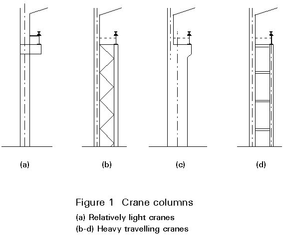
Handling facilities in simple portal frame buildings are often provided by light overhead travelling cranes carried on crane runway girders supported on brackets secured to the columns, see Figure 1a.
The maximum capacity of cranes supported in this manner is about 100kN. Above this capacity, it is better to provide a separate leg or to increase the depth of the column below the crane runway girder to give adequate support.
When an overhead travelling crane is introduced into a building, special care must be taken to ensure that the building is adequately braced in both directions. It is also worth mentioning that, where heavy cranes are involved, the crane runway girders may be subjected to severe fatigue conditions.
The support method of the crane runway girder depends on the magnitude of the reactions being transmitted, in relation to the strength of the structural framing of the building.
Some typical arrangements ranging from the lightest to the heaviest are shown in Figure 1. A separate crane column, as shown in Figures 1b and 1d is attractive for heavy cranes because it permits the effect of the crane to be considered isolated. However therein lies a danger, since the displacement of the building column could induce overstress in the connection between the two columns. A correct and more realistic approach is to analyse the columns as one.
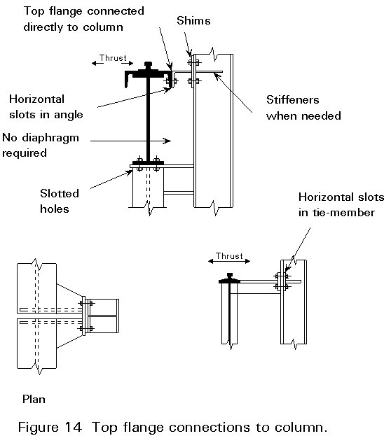
Careful consideration should be given to the transfer of the horizontal forces from the top flange of the girder to the column. This connection should:
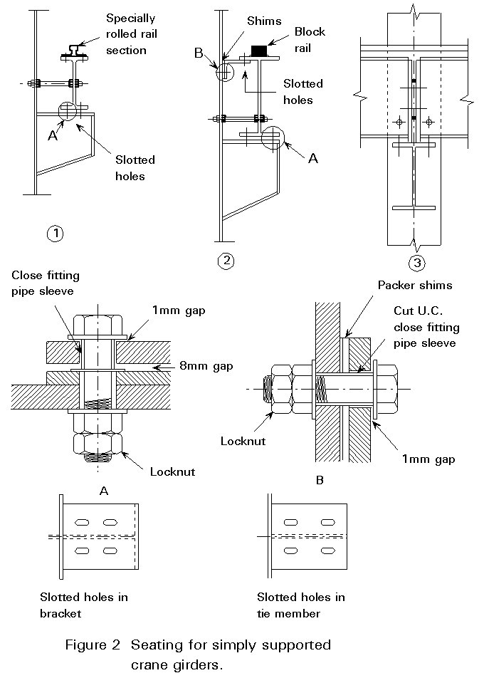
A very important aspect is the need for adjustment. It is impossible to erect building frames to the tolerance required by the crane manufacturer and it is therefore essential that the whole crane runway girder can be adjusted up to 10mm with respect to the building columns. Therefore, slotted holes and shims are required, as shown in Figure 2.
Free rotation at the supports of crane runway girders is important in order to prevent bending and torsional moments in the columns.
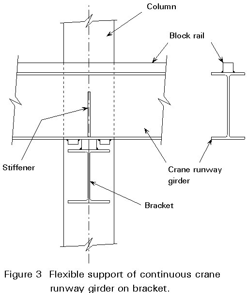
Rotation at the supports of a continuous girder can be realised by appropriate, flexible detailing as shown in Figure 3.
Rotation at the end of a simply supported girder results in a longitudinal movement of the top flange in relation to the centre line. The member which connects the top flange to the building column must therefore be capable of allowing free longitudinal movement without becoming overstressed. A simple flexible plate may be satisfactory when the movements are less than 1mm, but a connection with slotted holes is a safer solution in most cases (see detail B, Figure 2).
Another vital aspect is that the distance between the two columns of a portal frame at the height of the rail changes with the loading. The change in distance between two load cases can easily amount to 1/180 of the column-height. The wheel flange clearances must therefore be much larger than immediately expected (often 50 mm or more are recommended).
Longitudinal bracing of the building and crane runway girders can be arranged in several different ways:
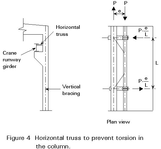
If the last method is used, there must be an effective restraint to the crane brackets to prevent torsion in the column. This restraint is normally obtained by a horizontal truss, as shown in Figure 4.
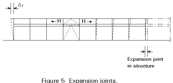
The ideal place for the braced bay is half-way between the expansion joints in the crane runway girder, or in the middle of the building, see Figure 5. This arrangement prevents the build up of axial compressive forces due to temperature rise, which could cause buckling of the crane runway girders. Furthermore, it forces the expansion in two directions, and thereby minimises the total movement. Only the columns below the crane runway girder are deformed. It is the magnitude of the secondary stresses associated with this deformation which limits the distance between the expansion joints. The maximum allowable distance between the expansion joints depends on the horizontal longitudinal displacement capacity of the columns bearing the crane runway girder - see Figure 5.
A method of transferring the axial forces in a simply-supported girder directly across the joint at the support is shown in Figure 2.3. The detail also shows an effective method of supporting the girders by using load bearing stiffeners. Attention has to be paid to the local eccentricity of the bearing stiffener with regard to the web of the bracket.
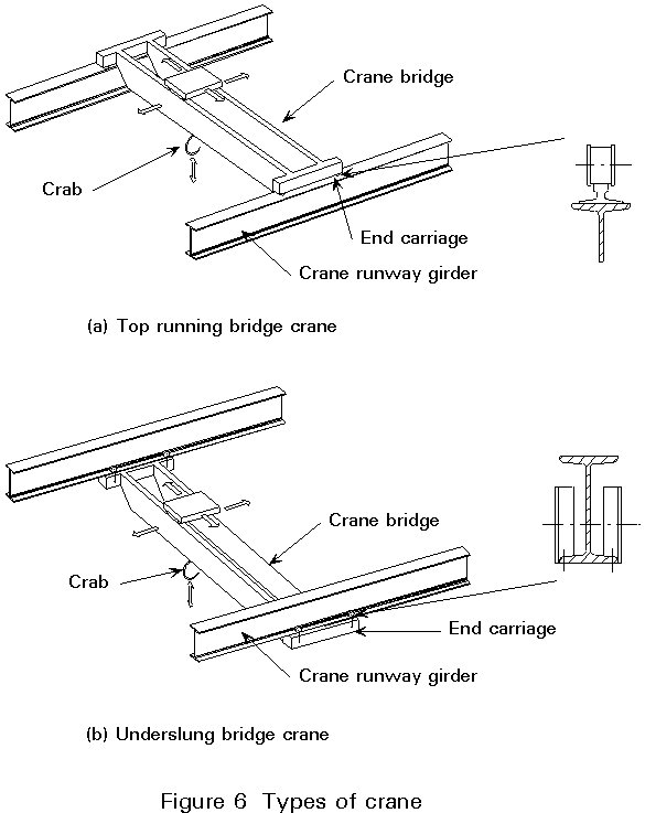
The most common types of cranes running on elevated runway girders are:
Loads from crane wheels have a static and a dynamic component. Both components are functions of time and vary with crane position and the magnitude of the load. The loads handled by the crane consist of a spectrum of light, medium and heavy loads. The dynamic forces due to acceleration and braking, hoisting and unevenness of the rails also vary from installation to installation.
To ensure economical design of cranes, they are normally divided into several classes depending on the frequency of their use, the average ratio of the loads lifted to the safe load, and the dynamic effects experienced in service. In this way it is possible to assess the fatigue risk to the crane and its runway girder during its design life.
Classification is based on two factors:
Selection of values for frequency of use and state of loading determines the final classification of a crane.
The crane rail and its interaction with the top flange of the girder has a very strong influence on the performance of the crane. It is, therefore, important to know what type of crane is going to be applied when designing the crane rail and runway girder. Loading characteristics should be adopted which are in accordance with the crane which will probably be installed. These characteristics can be obtained from manufacturers manuals. In practice it is sometimes impossible to prepare the design of the crane and the crane runway girder at the same time because the crane is ordered much later than the building structure. The result may be a poor design leading to problems such as excessive wear of the crane rail and crane wheel flanges or fatigue cracking in the upper web of the girder.
The crane rail must meet the requirements for protecting the top flange from wear and for distributing the wheel loads evenly over the greatest possible length of contact. The crane rail must therefore have:
Two types of crane rail are shown in Figure 2:
There are two types of splice:
Longer rail lengths can be obtained rather by welding than by bolting. Welded splices are normally superior to bolted splices because the welded joint avoids a gap and gives a step-free running surface. Special care is required in the welding operation if there are high carbon and manganese contents in the steel.
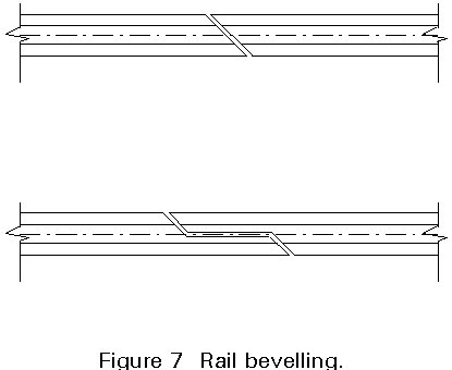
Expansion joints in rails must be provided on long runways when rails are fixed to the girders. They should coincide with joints in the main girder. A gradual transfer of wheel load from one rail to another is ensured if the ends of the rail are bevelled as shown in Figure 7.
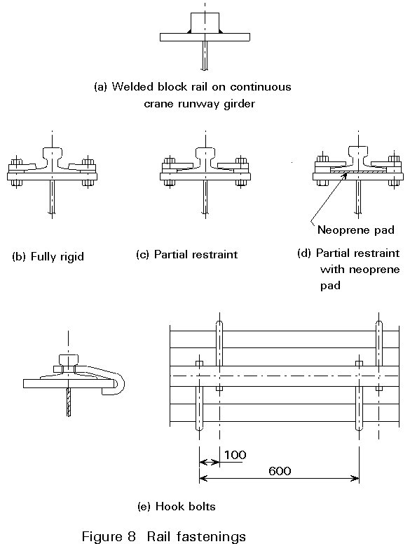
Various types of rail fastenings are shown in Figure 8. The traditional approach is to provide a fastening which restrains the rail in all directions. The fastening of block rails is always by shop welding. The fastening of specially rolled rail sections is normally obtained by a fully rigid clamp or by welding the rail to the flange of the crane runway girder.
Welding has the advantage that the rail can be accurately located on the girder centreline due to the fact that lateral adjustment is possible. However the use of welding gives problems in some cases. For example:
Modern practice tends towards a fastening which gives partial restraint, as shown in Figure 8c. The rail is restrained in the vertical and lateral direction, but the clamps allow the rail to move in the longitudinal direction.
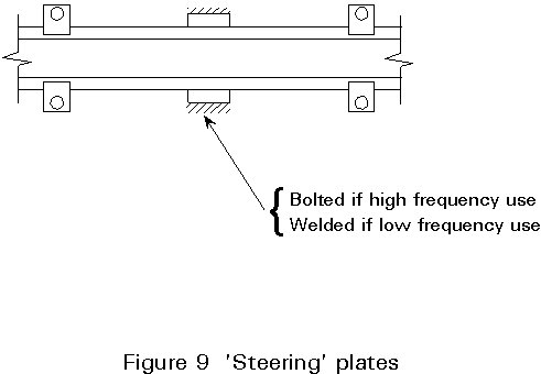
Figure 9 shows a very economical method, for heavy duty applications, of obtaining lateral restraint by site welding 'steering' plates between the clamps instead of using high strength bolts in the clamps to eliminate the possibility of movement. This type of fixing has to be checked for its influence on the fatigue of the crane runway girder.
The static wheel loads are exceeded during operation of the crane as a result of impact, inertial effects and other dynamic effects. These effects can also result in lateral forces at the top of the crane rail. The main factors to be considered are:

These dynamic effects can be approximated by multiplying the static wheel loads with an appropriate factor which may range from 1,0 to 2,0.
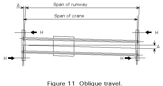
Oblique travelling of the crane can also induce lateral loads, as shown in Figure 11. The forces on the rail are acting in opposite directions on each wheel of the end carriage and depend on the ratio of crane span to wheel base.
The longitudinal forces due to crane acceleration and braking should be verified by calculations, when data on masses of the moving parts and their accelerations are known.
The end stops placed on the crane runway girder must be designed to take the crane buffer force. The buffer force is calculated from the kinetic energy of the mass of the crane, but without the lifted load due to the fact that it is suspended from the ropes. Another approach is to use electronic devices to stop the cranes at the ends, yielding a more beneficial loading situation for the structure supporting the crane runway girder.
Other loads that need to be considered are:
For more quantitative information on loads to be taken into account in designing a crane runway girder, national codes or crane manufacturer's documentation should be referred to.
The loads transmitted to the rail produce a triaxial stress state in the flange and the upper part of the web. The stress components are:
To make a realistic assessment of the stresses, the following design hints could be given:
During the conceptual stage of the design of the crane runway girder the fundamental questions are:
In some countries, simply-supported girders are preferred; in others continuous girders. When continuous girders are used, special attention should be paid to:
Figure 12 shows some cross-sections used for crane runway girders. For small spans and light-to-medium crane loads, it is normally possible to use rolled-beam sections. In some cases reinforcement may be necessary to give resistance to lateral forces (Figure 12a-c).
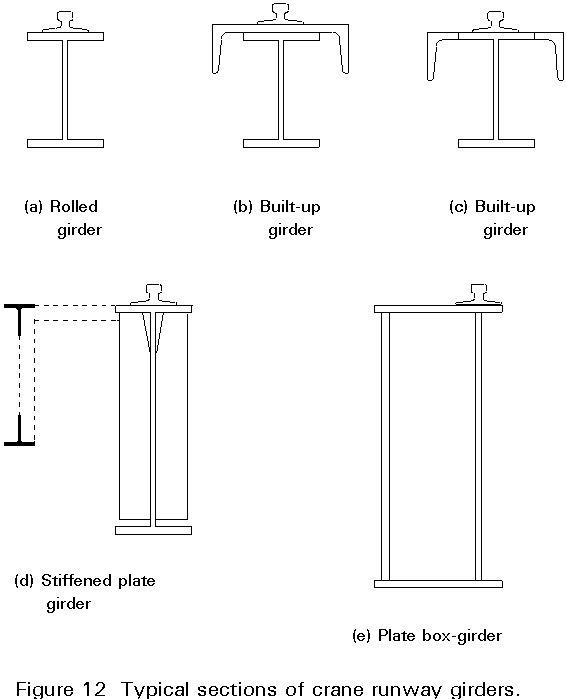
Single web plate girders are suitable for the majority of heavier cranes. Their insufficient resistance to lateral forces is normally solved by introducing horizontal bracing, as shown in Figure 12d.
Plate box girders are popular for the crane itself but are seldom used for the crane girder. The rail must be situated directly over the inner web of the box girder, so that transverse flexural stresses in the top flange plate are avoided, as shown in Figure 12e.
High strength steel is seldom used in crane runway girders because fatigue considerations limit the permissible stresses quite severely and thus reduce the economical advantages (the fatigue strengths of mild and high strength steel for welded structures are the same). Additionally, deflection and lateral-torsional buckling considerations also prevent the designer from gaining advantage from using high strength steel.
A general set of rules to assist the choice of optimum depth of crane runway girders cannot be given due to the variety of load cases and the differences in the cross-sections normally used. As a rough guideline, the usual range of girder depth-to-span ratios is between 8 and 14. The deflection limitation may dictate a larger depth, especially where spans are long.
The design of crane runway girders has some special aspects which are not often present in the design consideration of other types of girder:
The degree of refinement required in considering these special effects during design, depends very much on the class of the crane.
One of the most important decisions in connection with the design is to determine how far to go in minimising the mass of steel. Good design must take into consideration all costs during the design life of the crane installation. A very light design may promise a low first cost, but could give rise to large maintenance costs resulting from a need for frequent repairs.
The predominant loading is vertical. The crane runway girder is normally directly supported by its seated connection on the column or by means of a bracket. The best way to secure a direct flow of stresses from the crane runway girder to the column or bracket below, with a minimum of eccentricity, is by means of welded brackets, as shown in Figure 2.
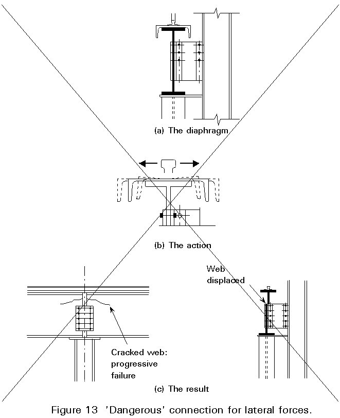
The next principal loading is transverse. Figure 13a shows a dangerous detail frequently used on lighter crane girders to resist lateral forces. Figure 13b illustrates the reversible strain to which the girder web is subjected - an action leading to the result shown in Figure 13c. The failure could easily be prevented by simply connecting the top flange directly to the column, as shown in Figure 14. The top flange acts as a horizontal beam delivering its reaction to the column.
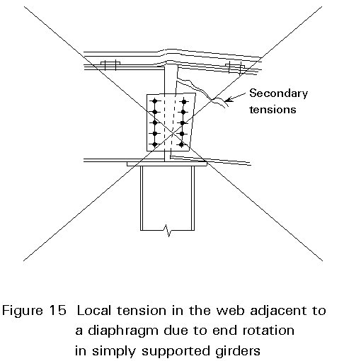
Another effect caused by this bad detail is shown in Figure 15. The vertical deflection of the crane girder rotates its ends on the column seat. If the connection is not designed for that purpose the result is high shear on the upper fasteners, and local tension in the web, which could lead to failure in that area of the web.
A continuous girder offers a possible solution to the rotation problem when a flexible detail as in Figure 3 is chosen.
The following maximum values for the deflection of the crane girder must normally not be exceeded in order to avoid undesirable dynamic effects and to secure the function of the crane:
In the absence of more detailed calculations it is acceptable to assume that the top flange resists the whole horizontal force. The rigidity requirement for horizontal deflection is essential to prevent oblique travelling of the crane.
The vertical deflection is normally limited to a value not greater than 25 mm to prevent excessive vibrations caused by the crane operation and crane travel.
It becomes uneconomical to use unstiffened webs when girder depths increase, because a relatively large proportion of the girder material is in the web. Web stiffeners serve the purpose of:
Twisting of the top flange caused by lateral forces has to be resisted by the web alone, if no web stiffeners are present. When the girder is relatively deep and the lateral forces are high, it will not be possible to omit web stiffeners. The distance between the stiffeners must not be so large that twisting of the top flange becomes too large at the mid-point.
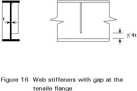
The method of attaching the stiffeners to the web and the flanges must be detailed carefully to prevent fatigue failure. Fatigue in the tensile flange can be averted by providing a gap of 4t between the end of the stiffener and the bottom flange, as shown in Figure 16. However there will still be a possibility of fatigue in the web at the termination of the stiffener.
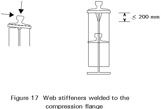
However, the detail shown in Figure 17 is normally considered to be the best solution. The stiffener should be welded to the compression flange so that relative movement of the flange in relation to the web due to lateral forces is totally prevented. The stiffener should be coped a maximum of 200 mm.
The simultaneous effects of torsion induced by lateral forces and lateral-torsional buckling can be considered in several ways. It is often difficult to decide how rigorously the structural calculations should be done. Lateral forces due to off-vertical lifting, inertial effects and oblique travelling can only be estimated approximately. Values obtained from relevant codes together with the use of duty factors given in the Codes is the only means at the designer's disposal.
Torsion in the section is caused by:
The geometry of the top flange should be chosen from those alternatives that offer the best torsional resistance and the best lateral stiffness.
Crane runway girders are subjected to repetitive stressing and unstressing. The number of stress cycles that certain parts of the crane runway girder is subjected to may be two to four times the number of crane passages because each passage of the wheels causes stress fluctuations. This effect is one of the reasons why special care must be paid to the detailing of the top part of the crane runway girder.
The number of the crane passages is not easy to estimate. For design purposes it is assumed that the number of stress fluctuations corresponds to the class of the crane as specified in the Codes.
The critical details in fatigue design are the stiffener-to-flange, the stiffener-to-web, and the flange-to-web connections where severe concentrations of stresses exist. The following recommendations are made:
Crane runway girders require a special care in design and detailing. They should be regarded as a mechanical item. The uncertainties, especially regarding the transverse loads and the transfer of forces to the girders, have to be clearly recognised. In the following some guidance in obtaining the proper design is given: