ESDEP WG 14
STRUCTURAL SYSTEMS: BUILDINGS
To describe different types of spatial truss systems, and the design parameters to be considered. To give guidance on initial sizing and on analysis methods. To describe fabrication and erection procedures.
Lecture 1B.3: Background to Loadings
Lecture 6.3: Elastic Instability Modes
Lecture 7.12: Trusses and Lattice Girders
Lectures 13: Tubular Structures
Lecture 14.6: Special Single Storey Structures
The lecture provides an historical background and an overview of different types of spatial truss systems: double-layer grids, barrel vaults and domes. Design parameters are introduced and some rules for initial sizing are described. The principles of different methods of analysis are given. The lecture concludes by describing aspects of fabrication and erection particular to these structures.
For this lecture, trusses are defined as structural systems in which the members are interlinked so that they are only subject to axial compressive or tensile forces.
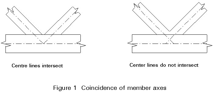
This definition assumes that no action is applied directly onto the members. All loads are applied to the joints which are known as 'nodes'. In case it is impossible to guarantee the coincidence of member axis, the bending effect resulting from this must be evaluated. It is particularly important to ensure that the axes of the members coincide (Figure 1). Only perfect pins could completely ensure compliance with this loading condition. The technological construction of assemblies deviates to some extent from this theoretical situation and, in effect, is one of the main difficulties associated with these structural systems.
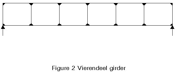
The lecture is concerned mainly with truss systems for roofs, which span in two directions (termed 'space structures'). Other arrangements are possible, such as continuous systems, based on the Vierendeel girder (Figure 2) in which diagonal bracing members are unnecessary because the bending behaviour is predominant, rather than the axial one; the resulting voids can be used to accommodate mechanical and electrical services.
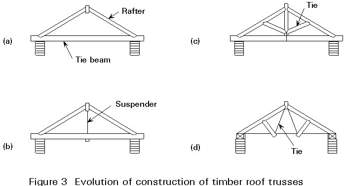
Until the 1960s, almost all truss systems were two-dimensional. They had developed from timber roofs, which themselves had evolved from a basic triangular arrangement to more complex shapes (Figure 3). The need to lighten long tie beams and reduce bending stresses (Figure 3a) had led to the introduction of a suspender (Figure 3b). A similar concern to reduce bending of the rafters led to the introduction of diagonal members (Figure 3c). By dividing the suspended member in two, the familiar arrangement of Figure 3d was obtained.
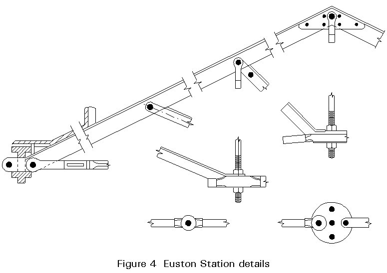
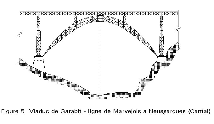
The use of metal became dominant in the 19th century for all types of structures except domestic buildings. Articulated systems (Figure 4) commonly used for roofs of railway stations were perfect examples of the two-dimensional triangulated system. The second half of the 19th century was characterised by some remarkable achievements, for example the Garabit viaduct in France (Figure 5) and the Maria Pia bridge in Oporto, both designed by Eiffel.
Although spatial systems were proposed early in the 20th century, their use in practice has arisen from the more recent development of computer methods for analysis, the functional need for spaces free of columns and from demands of architectural appearance.
Different types of spatial truss systems are normally classified according to their general shape. The following may therefore be distinguished [1]:
In each case it is advisable to distinguish between single and double or even triple layer grids. The number of layers depends on the span. A third characteristic lies in the geometry chosen for the system of members in the layers and possibly in the composition of the bracing of the layers.
These grids are mentioned only as a reminder that these systems are beam grillages which work in bending and torsion, rather than under axial compression and tension.
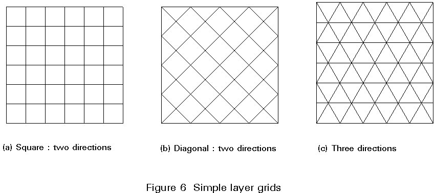
Depending on the directions assigned to the members, grids may be identified in two, or three directions (Figure 6). Grids in two diagonal directions are more rigid (beams follow the direction of the principal stresses of the equivalent plates) and are widely used. Utilisation is restricted to about 10m of span.
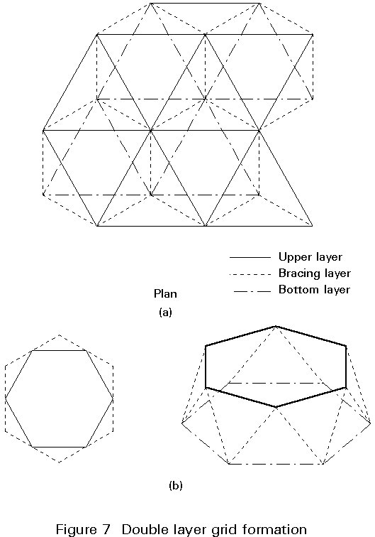
These grids comprise two systems of members on two parallel levels (upper and bottom layer). Both these systems are interlinked by bracing members (web members) (Figure 7). Two types of double layer grids may be distinguished (Figure 8):
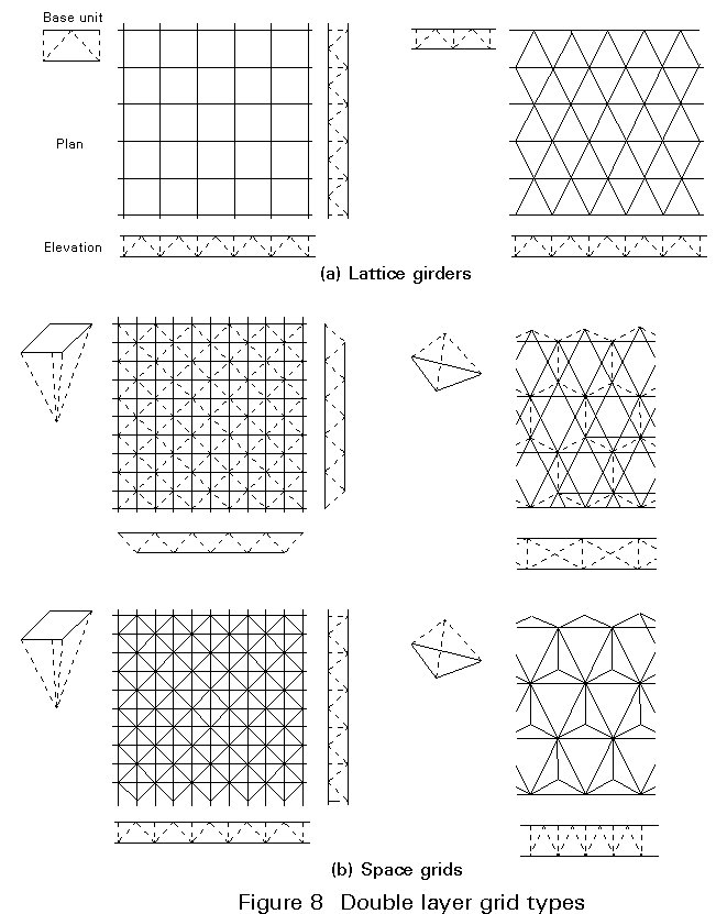
These systems are suitable for spans up to 100m. For greater spans, it is necessary to incorporate triple layer grids, to avoid long members otherwise necessary with the increased depth.
The size of the constituent modules depends on several factors, principally: span, load, cladding system, type of node, transportation and erection facilities.
For spans of between 30 and 40m, member lengths of about 1,5m to 3m are acceptable.
The advantages of double layer grids are numerous:
From an economic point of view, it is important to have a minimum number of nodes. It is therefore necessary to compromise between this criteria and those determined by the choice of module sizes.
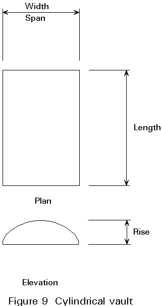
In the history of construction, cylindrical vaults appear as an evolution of arches. The use of metal has enabled construction to be carried out with factory prefabricated elements which may be assembled on site. The first example to recall is the Crystal Palace which was erected by Joseph Paxton for the Great Exhibition in 1851.
This shape has proved to be suitable for roofs of halls, railway stations and sports facilities, e.g. in-door tennis courts.
Maximum efficiency may be attained for shapes with rectangular surfaces and a length/width ratio of between 1 and 2. The optimum shape (rise/span ratio) is in the region of 0,15 to 0,20 (Figure 9).
Several layer geometries are possible (Figure 10). In practice, three directional systems offer the most advantages. They may usually be analysed by assuming pin-jointed behaviour for the nodes. This assumption does not hold, however, for some systems where bending rigidity must be taken into account, e.g. for a vault composed of prefabricated elements rigidly joined by high strength bolts.

The sensitivity of these systems to asymmetrical actions, in particular to wind, should not be underestimated. Such actions can even bring about force reversal in the members, which is an additional reason for choosing a three directional geometry in which the length of all elements is identical.
In the same way, choice of support conditions along the boundaries influences force distribution.
Economical spans for single layer vaults are in the region of 20m. Spans may be increased by inserting diagonal elements. They reach 60m for double layer systems, in some cases even more. Appropriate weights for double layer systems vary between 0,13 and 0,25kN/m2 depending on the intended shape, support conditions and on the geometry of the sheets (for a uniform load of between 0,75 and 1,50kN/m2).
Domes constitute one of the most ancient forms of construction. However big or small their size, the outline of the two-dimensional support is normally circular on plan.
Skeletal dome structures can be classified into several categories depending on the orientation and position of principal members. The four more popular types are: ribbed domes, Schwedler domes, three-way grid domes and parallel lamella domes (Figure 11).
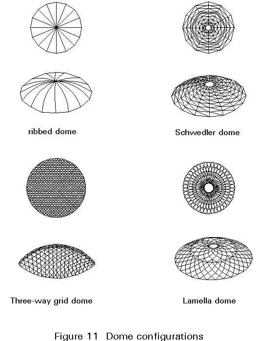
Domes are of special interest to architects and engineers because they provide the maximum enclosed volume for minimum surface area. In the last 25 years construction with steel sections has largely replaced reinforced concrete. The first two examples concern single and double layer systems. These systems permit spans of about 40m and more than 100m respectively. Some double layer solutions have encouraged 'record' spans of more than 200m.
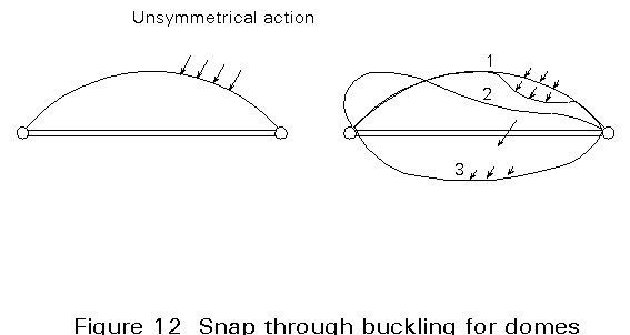
The accurate analysis of domes has only been possible with the introduction of computers which have allowed an accurate study of elastic behaviour. It is important to note that large span single layer domes subjected to asymmetrical actions can experience global instability effects. In addition to consideration of local buckling of compression elements, specific attention should be drawn to possible global 'snap-through' buckling (Figure 12). The action of wind is not very well known; application of factored actions to a non-critical load case does not necessarily cover the most unfavourable situation and recognition of an appropriate excess weight does not necessarily bring about the most unfavourable situation.
From the physical point of view, it is important to stress the difference in behaviour of domes with respect to cylindrical vaults. The sensitivity to asymmetrical actions and the resistance to global buckling phenomena is strictly connected to the rigidity of the geometrical shape. For cylindrical vaults, their surface has a single curvature, so it can be developed on plan. In contrast, domes, having a double curvature, resist any actions by virtue of the shape itself.
Definition of the geometric arrangement of elements, whether for a single or a double layer construction, is a difficult problem to resolve. Research is aimed at using fewer different lengths for the members. Moreover, it is important to check that the polygons defined are as similar as possible, in order to facilitate cladding. Fuller designed one of the first big developments: the dome of the American Pavilion in Montreal (1967) which is composed of two interconnected layers and constructed with welded tubular sections; the resulting structure is 5/8 of a total sphere, with a diameter of 75m.
At the conceptual design stage it is important to define the geometry of the structure, given that determining support positions is an important factor in the strength and rigidity of the system.
Geometric design parameters are:
The choices made directly influence the number of members converging on each node and on the connecting angles between these members; these two parameters determine the feasibility of the nodes. Too many elements meeting at different angles and lack of repetition are hindrances to construction efficiency. The choice of spacing of grids should be related to geometric connections, particularly the connection of the two-dimensional sides of a polyhedric surface.
Choice of support conditions does not pose any specific problems, but it does affect behaviour.
It should be noted that, because of the low weight of these structures, the weight of the equipment supported by the structure should not be negligible. Similarly, actions resulting from the method of construction should be carefully examined. The effects of concentrated actions and of partially distributed loads, which are greater when the total loading is not symmetrically distributed, should be examined. Except in specific cases, dynamic actions can be replaced by enhanced static actions.
Every project is undoubtedly an individual case. Nevertheless, it is possible to establish sequential steps in the development of the design. Most importantly it should be noted that, for a shape to be covered in any pre-determined way, two distinct methods can be used to define the general surface:
Once the overall geometry has been established, the designer must decide on the number of layers. This design depends basically on the free span, and also on the geometric distribution of the members in and between the layers. Choice of frequency of mesh is important for reasons of resistance and cost, as well as for aesthetic reasons. Choice in the geometry of the network of members directly influences behaviour of the systems. For example, in the case of double layer grids, an examination of different geometric arrangements has confirmed the importance of adopting an arrangement where directions of the members in the two layers are set at 45°.
It is therefore possible to examine the structural behaviour under appropriate combinations of actions. Choice of support conditions has a big influence on the distribution of internal forces and size of the deflections. The possible use of multi-point supports is an important advantage of spatial trusses. Definition of the areas of the cross-sections of the elements may lead to a process of optimisation suitable for the design model.
It is possible to provide further information in the case of double layer two dimensional grids. The curves in Figure 13 illustrate the variation in weight suitable for different structural depths with the slenderness ratio for seven different geometries (Figures 14-20).
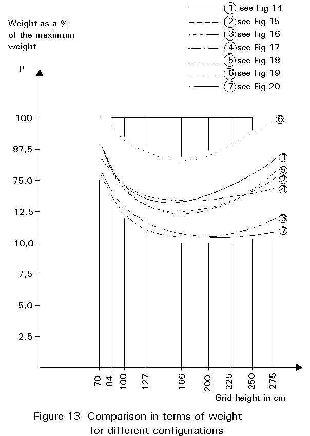
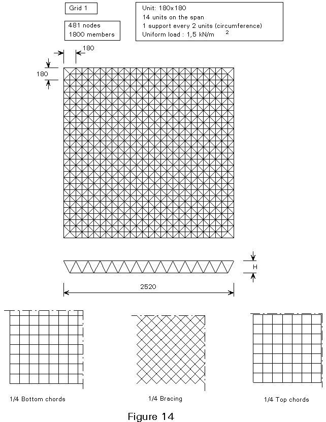
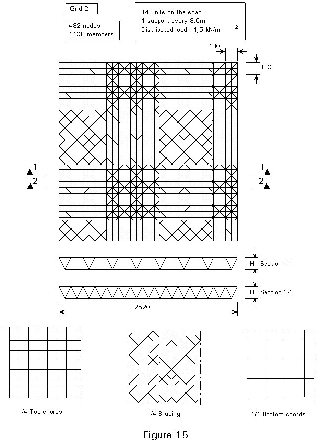
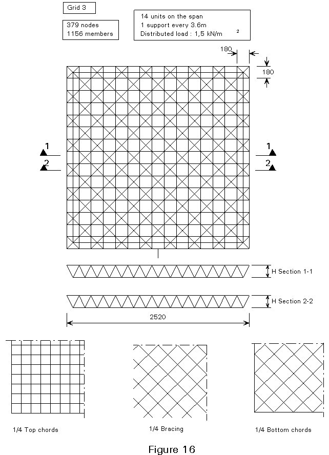
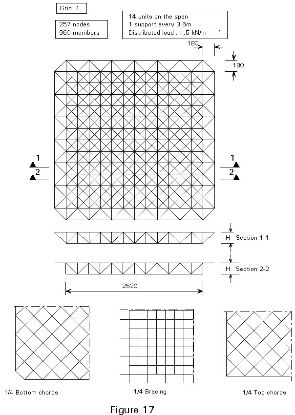
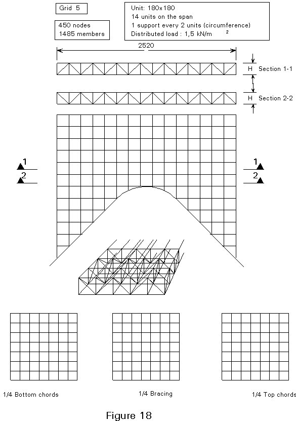
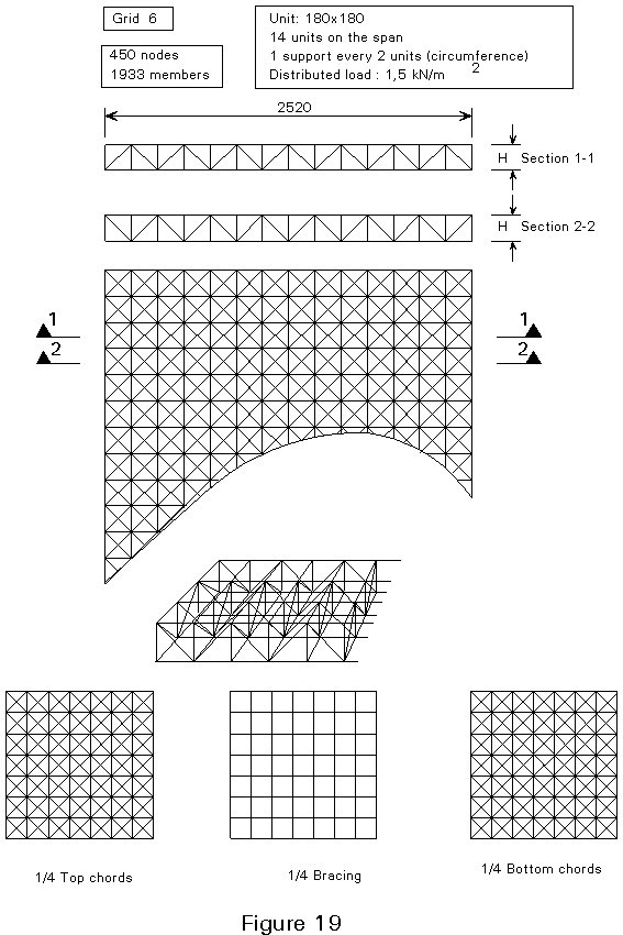
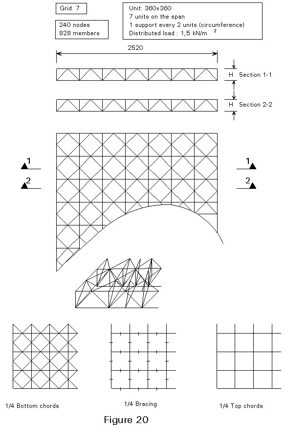
Calculations were made for the case of a square outline with peripheral supports under each node, assuming a uniformly distributed load. In addition, the following data have been assumed:
It is also important to consider the relation between the size of the mesh element and depth of the grid.
As soon as the overall shape of the structure is defined, it is necessary to choose the structural system.
A wide variety of structural systems is available, which can fulfil the geometrical requirements of the design. However, they cannot all provide the load carrying capacity which is required to resist the most unfavourable design loading conditions.
The sizing of the cross-section of members is a task of the designer, whereas the producer of the structural system must guarantee that the node-member combination should be able to give a joint of full strength type. Only by means of appropriate qualification procedures can this guarantee be realised.
The qualification procedure should demonstrate that the system for the space structure is based on a basic node - member joint which is a full strength type. The demonstration can be done by calculation and by tests.
On the one hand, it is possible to model the node-member joint by means of finite element techniques. However, it is not prudent to rely solely on these numerical results.
On the other hand, only experimental evidence can fully demonstrate the actual behaviour of the system.
For these reasons, the qualification procedure should be based mainly on laboratory tests, the results validating the calculations. A suggested procedure could be based on the following phases:
The objective of an analysis of truss systems is to determine the values of the variables necessary for sizing purposes and for those required to size their supports. The variables generally required may be:
The study has to be made for several cases of actions and combinations of actions. The most unfavourable cases are used as the basis for design.
Depending on the type of problem being examined, it is not necessary to determine all unknown quantities. The methods of analysis available can be classified as follows:
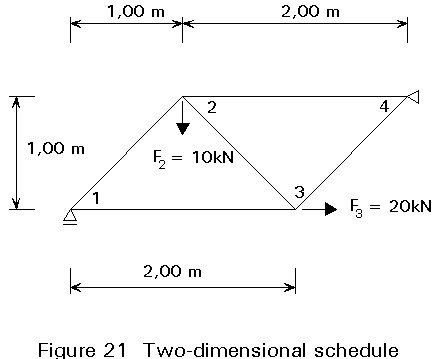
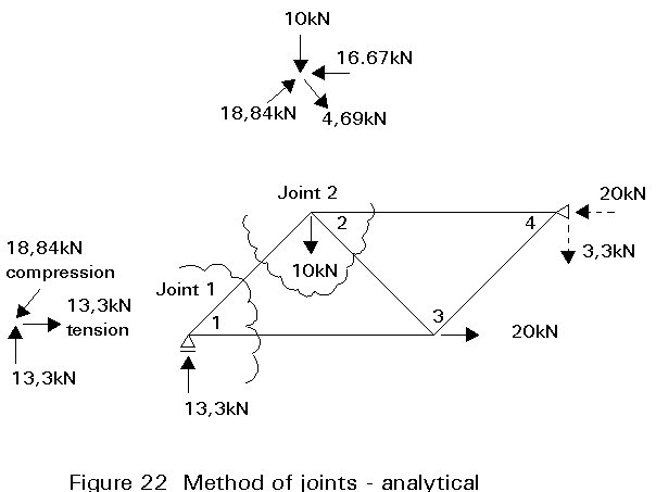
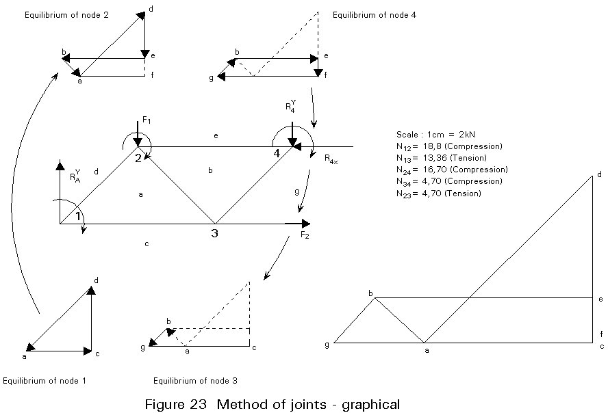
i. Method of joints: applicable to two-dimensional systems which are internally isostatic (Figure 21), for which the reactions have previously been determined. It is possible to determine the forces in all members. They can be determined by analytical or graphical methods (see Figures 22 and 23).
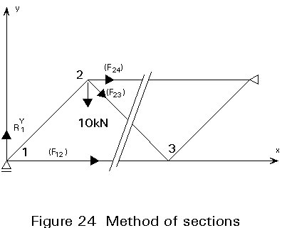
ii. Method of sections: in certain cases, this method can give direct access to internal forces in a limited number of members selected by the designer. It is used, for example, for preliminary design work in order to assess the maximum forces in a triangulated system (Figure 24).
iii. Displacement method: This is the most general method. It is applicable to two-dimensional and spatial systems, isostatic or hyperstatic. It gives values for all unknown quantities: internal forces, displacements, reactions.
In addition to use of principles which are common to all structures in respect of actions and their combinations, Eurocode 3 [2] allows a perfectly pin-jointed model for global analysis.
Furthermore, it is considered that all actions are applied at the systems nodes. It is sufficient to assume linear-elastic response.
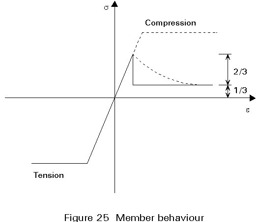
Calculations in the elasto-plastic range can be done by using simplified models of the members such as is shown in Figure 25. The results show that a reasonably stable response of compression elements (after the ultimate load of a member is reached) can be achieved and the forces transferred to the adjacent members from that which has reached its ultimate resistance.
The methods described in the following paragraphs are all based on the application of equilibrium to the forces applied by the members to the nodes. The pin-jointed analysis used for triangulated systems simplifies the formulae for equilibrium: in general, the three equations relating to translational equilibrium are necessary.
Attention is drawn to the fact that the methods described do not take account of:
It is therefore necessary to evaluate carefully the significance of factors associated with failure to ensure the appropriateness of the assumed models, either by making additional calculations, or if applicable, by using more detailed calculation models, e.g. the generalised displacements model which takes account of stiffness in flexure and in torsion, when the given joint is far from the pin-jointed assumption.
This is the most general method applicable in all cases of space structures. The behaviour of the materials is assumed to be elastic and linear.
The principle of the method lies in resolving a system of linear equilibrium equations as follows:
[K] {D} = {F}
where
[K] is the structure stiffness matrix.
{D} is the unknown displacement vector.
{F} is the vector of known actions.
The components of {D} corresponding to the fixed supports are zero. The corresponding equations, the second components of which are the reactions, do not therefore appear in the corresponding system of linear equations. Determination of the displacements enables the internal forces to be calculated. This method is normally implemented by computer software.
The very nature of spatial trusses encourages research into maximum standardisation, linked to individual component manufacture, and requires particular attention to problems of precision.
It is advantageous to design spatial trusses with a minimum number of different members; the same criteria should be used for the nodes. It is common to use members with the same section sizes, independent of their different stress state due to their location in the structure. For tubular sections, it seems reasonable, however, to keep the same external diameter and to vary the wall thickness.
Installation methods may cause greater deformations and forces during erection than after completion. The designer should consider the erection phases when sizing the elements.
The structural system is characterized by the combination of three main components:
Members
Hollow sections are essential for a number of reasons. In particular, tubular sections are generally used because of their large and uniform radius of gyration.
Nodes
The dream of a 'universal' node has not yet been realised. Several parameters govern the design of nodes. Nodes can be connected mainly by welding, bolting or by special fabrication. Except where pretensioned bolts are used, bolted connections reduce the resistance of net-sections. Some authorities prefer welding for large spans, even if it is difficult to guarantee the quality of welds in site. One of the determining factors in the choice of nodes is the number of members to be assembled. Apart from structural influences on the node itself, this problem is linked to the way the members are connected to the node and to considerations of space and ease of installation. The regularity of geometry resulting from the node determines the entire geometry of the structure. Significant progress has been made in this area through computerisation linking design and fabrication. As a result, it is possible to fabricate nodes by varying the angles of incidence of the members.
Five 'kinds' of nodes may be identified, Figure 26:
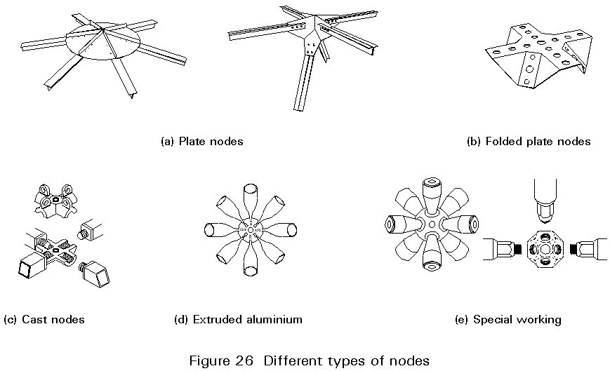
Plated and folded nodes are usually connected to the member ends by means of bolted connections, but also welding can be done.
The node is a critical element when evaluating the cost of spatial structures: one node for 2,5-3,0m2 would seem to be an economical solution.
Connections
The node-to-member joining system determines how the ends of the members must be treated. Five processes may be described, for example, (Figure 27):
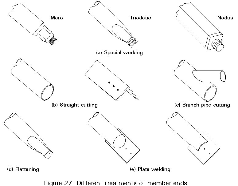
It is clear that not all these systems give full strength joints.
Methods used may be listed in three categories:
a. Erection of separate members, each one lifted into position and connected to the work already assembled.
b. Erection of sub-assemblies: this is an intermediate stage whereby the members are connected in sub-assemblies, either in the factory or on site. The sub-assemblies are lifted into final position and connected to the work already assembled.
c. Lifting of the whole space structure, which is assembled on the ground on site. Various methods may be considered ranging from the use of vertical construction parts as lifting masts to cranes.
The choice of one of these three methods depends on:
In a) and b) it is essential to predict the need for any temporary supports that may be necessary where the structure achieves stability only when it is complete. The many phases in erection should be carefully examined so as to avoid intermediate structural behaviour which is less favourable than that for the final state of the structure.
Lifting the whole space frame has the following advantages:
Hoisting is a critical stage in erection. Lifting points should be carefully examined. Lifting should be carried out in the best meteorological conditions and certainly not in wind. Once in position, the structure should be connected to the work already erected. Precise regulating devices should be planned in advance in order to facilitate connection and fixing. The lifting stage can be a determining factor in the design of the structure.
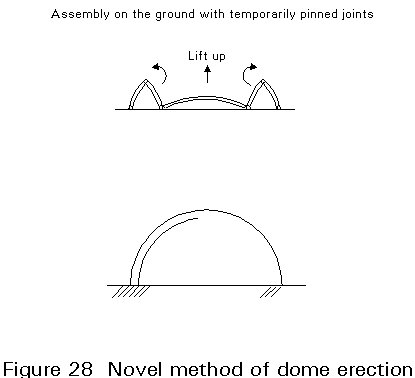
A new approach has been used in Barcelona for the erection of the dome of the Olympic Palace. It involves the fabrication of the dome on the ground in five portions which are temporarily pinned to each other (Figure 28). The central portion is then lifted and the remaining segments of the dome locked in the final position.
Different methods of execution may be considered depending on the type of structure and place of installation.
For example, it is possible to carry out assembly using a launching method borrowed from bridge construction, etc. There is no limit to the list of solutions. The erection method chosen depends on the imagination and know-how of the designer within a particular context.
× two-dimensional grids.
× cylindrical vaults.
× domes.
[1] Makowski, Z.S.: "Structures Spatiales en Acier", Centre Belge-Luxembourgeois d'Information de l'Acier, 1964.
[2] Eurocode 3: "Design of Steel Structures": ENV 1993-1-1: Part 1.1: General rules and rules for buildings, CEN, 1992.