ESDEP WG 6
APPLIED STABILITY
To describe the elementary elastic instability modes and to derive the principal critical loads for columns, beams and plates.
Lecture 6.1: Concepts of Stable and Unstable Elastic Equilibrium
Lectures 6.6: Buckling of Real Structural Elements
Lecture 7.7: Buckling Lengths
Worked Example 6.1: Energy Methods I
Worked Example 6.2: Energy Methods II
This lecture explains how critical buckling loads are determined by solution of the differential equilibrium equations for the structure. The critical loads, assuming simple loading and boundary conditions, are then calculated for the principal cases, namely:
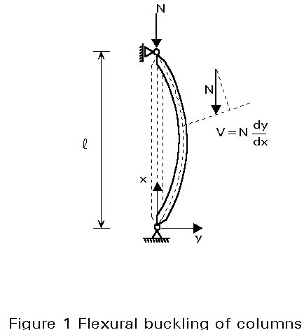
Instability can occur in all systems or members where compression stresses exist. The simplest type of buckling is that of an initially straight strut compressed by equal and opposite axial forces (Figure 1).
Other buckling modes also of great practical interest in steel constructions, are:
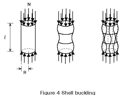
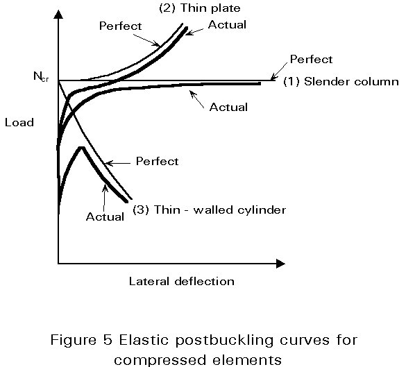
The fundamental differences in behaviour of columns, plates and shells are shown in Figure 5. For behaviour in the elastic range the critical load and the maximum load carried by an actual (imperfect) column are in reasonable agreement. For the plate, if the postcritical strength is achieved with acceptably small lateral deflections, a greater load than the critical load might be acceptable. For thin-walled cylinders, however, the maximum load in the real (imperfect) situation is much less than the theoretical critical load.
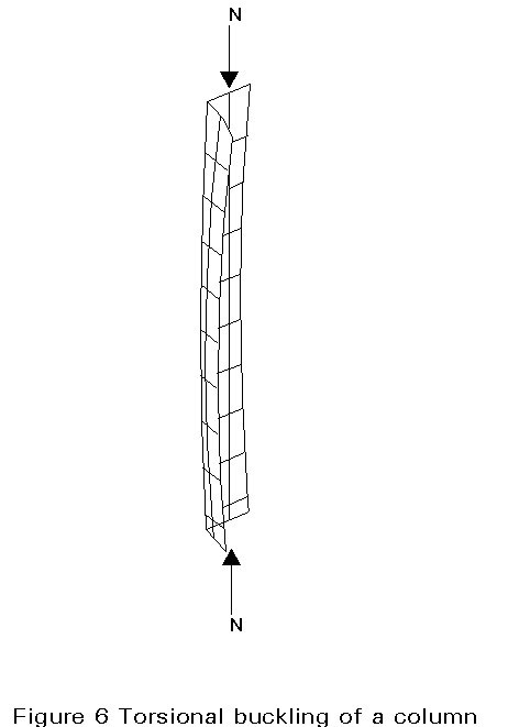
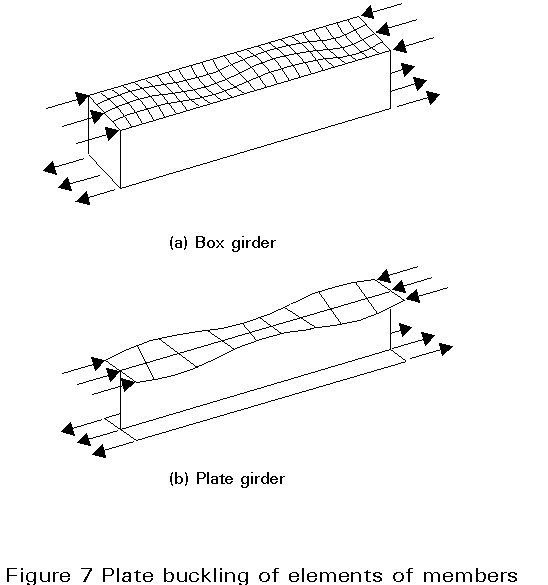
For compressed struts, the flexural buckling illustrated in Figure 1 is not the only possible buckling mode. In some cases, for example, a torsional buckling (Figure 6) or a combination of torsional and flexural buckling can be seen; if a member is thin-walled, one can also observe a plate buckling of the elements of the cross-section (Figure 7) which can interact with the overall buckling of the member.
Determination of the critical load using bifurcation theory takes advantage of the fact that the critical situation is associated with a neutral equilibrium condition; equilibrium in a slightly deflected shape can, therefore, be established, leading to differential equations which are simple to manage, at least for certain classes of structures. The critical load gives information on the level of stability of a system, or member; it is also used as a basic value (bound) for the calculation of the ultimate load for structures in danger of instability, as shown in later lectures. In this lecture, the critical loads are calculated by solving the differential equilibrium equations describing the phenomenon. These solutions are available only for the simplest cases of loading and boundary conditions. A general method for assessing critical loads, based on an energy approach is given in Lecture 6.4.
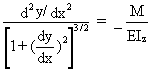
At the critical load, the stable equilibrium of the straight column is at its limit and there exists a slightly deflected configuration of the column which can also satisfy equilibrium (Figure 1). For this configuration, the bending moment at any cross-section is given, for a pin-ended strut, by:
M = N.y (1)
Using the differential equation given by simple bending theory, and considering large deflections:
 (2)
(2)
or the approximation
![]() (3)
(3)
which is reasonably accurate for loads approaching critical load and for small deflections; by introducing Equation (1) this becomes:
![]() (4)
(4)
where EIz is the bending rigidity of the column in the plane of buckling.
The general solution of this equation is:
y = A sin kx + B cos kx (5)
where
k2 = ![]() (6)
(6)
(only positive solutions, i.e. compression forces, are of interest).
A and B are constants of integration which must be adjusted to satisfy the boundary conditions:
y = 0 for x = 0 (7a)
and
y = 0 for x = l (7b)
The first boundary condition gives B = 0; the second one gives:
A sin kl = 0 (8)
which requires either A = 0 (in this case there is no deflection), or sin kl=0, i.e.
kl = np (9)
where n is any integer.
Finally, the critical load is obtained from the following:
Ncr,n = ![]() (10)
(10)
Figure 8 shows the first three buckling modes (n = 1, 2 and 3 respectively).
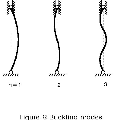
Normally, the smallest value of kl, and therefore of the critical load Ncr, which satisfies Equation (9) is obtained by taking n = 1; this critical load is called the Euler load; in the case where bracing is used, higher buckling modes may be decisive.
The critical load for a pin-ended column was calculated by Leonhard Euler in 1744. Historically speaking, it is the first solution given to a stability problem. The same procedure may be used for cases with other boundary conditions.
The critical load given above does not take into account the effect of shear forces; this can be done by adding the shear deformation:
g = ![]() (11)
(11)
where V, the shear force, is given by:
V = N ![]() (12)
(12)
and Av is the shear area of the cross-section.
By adding the change in slope of the deflection curve produced by the shear force, the differential equation of the buckling phenomena becomes:
![]() (13)
(13)
which gives the critical load:
Ncr* =  (14)
(14)
Thus, owing to the action of the shear forces, the critical load is reduced when compared to Euler's load. In the case of solid columns, the influence of shear can generally be neglected; however, in the case of laced or battened compression members, this effect may become of practical importance and should be considered.
When a beam is bent about its strong axis, it normally deflects only in that plane. However, if the beam does not have sufficient lateral stiffness or lateral supports to ensure that this occurs, then it may buckle out of the plane of loading, as shown in Figure 2.
For a straight elastic beam, there is no out-of-plane displacements until the applied moment reaches its critical value, when the beam buckles by deflecting laterally and twisting (Figure 2); lateral buckling, therefore, involves lateral bending and torsion. For the simplest case, of a doubly symmetric simply supported beam, loaded in its stiffer principal plane by equal moments (Figure 2), the differential equilibrium equations of the beam are as follows:
![]() (15)
(15)
E.It . ![]() (16)
(16)
where EIz is the weak axis bending rigidity; My is the lateral bending moment induced by the twisting, y, of the beam; GIt is the Saint-Venant torsional rigidity; EIw is the warping rigidity and M ![]() is the torque induced by the lateral deflection v.
is the torque induced by the lateral deflection v.
When these equations are both satisfied at all points of the beam, then the deflected and twisted position is one of equilibrium which can be found by differentiating Equation (16) and substituting Equation (15); then, the differential equation of lateral buckling is given by:
E.Iw ![]() (17a)
(17a)
or
Cw ![]() (17b)
(17b)
This expression was established, for the first time in 1899, by Prandtl. The general solution of this equation is:
y = A1 sinh k1 x + B1 cosh k1 x + A2 sin k2 x + B2 cos k2x (18)
where
![]() =
=  (19)
(19)
![]() = -
= -  (20)
(20)
in which A1, A2, B1 and B2 are constants of integration which must satisfy the boundary conditions:
y = 0 for x = 0 (21a)
and
y = 0 for x = l (21b)
![]() = 0 for x = 0 (22a)
= 0 for x = 0 (22a)
and
![]() = 0 for x = l (22b)
= 0 for x = l (22b)
Equations (21) and (22) show that, in the case of a so-called simply supported beam, the supports must prevent both lateral deflection and twist but the section is free to warp at the ends.
The four boundary conditions give:
A1 = B1 = B2 = 0 (23)
and
A2 sin k2l = 0 (24)
which requires either A2 = 0 (in this case there is no twist), or
sin k2 l = 0, i.e: k2 l = n p (25)
where n is any integer.
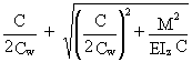
Substituting Equation (25) into Equation (20) and rearranging, using the smallest value of k2 l gives the critical moment for the beam:
![]() (26)
(26)
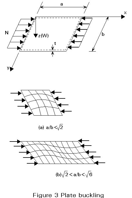
The simplest example of this phenomenon is that of a rectangular plate with four edges simply supported (prevented from displacing out-of-plane but free to rotate) loaded in compression as shown in Figure 3. As for compressed struts, the plate remains flat until the applied load reaches its critical value, at which time it buckles with lateral deflections.
The differential equation for plate buckling, established by Bryan in 1891, gives for the case shown in Figure 3:
![]() (27)
(27)
where D is the bending rigidity of the plate:
D = Et3/{12(1-n2)} (28)
The general solution of this equation is:
w = A sin mpx/a . sin np/b (29)
which satisfies the boundary conditions:
w = ![]() = 0 for x = 0 (30a)
= 0 for x = 0 (30a)
and
w = ![]() = 0 for x = a (30b)
= 0 for x = a (30b)
w = ![]() = 0 for y = 0 (31a)
= 0 for y = 0 (31a)
and
w = ![]() = 0 for y = b (31b)
= 0 for y = b (31b)
Substituting Equation (29) in Equation (27), gives:
N = 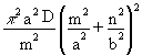 (32)
(32)
where m and n are the number of half-waves in the directions x and y respectively.
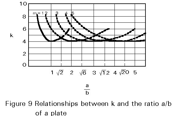
The smallest value of N, and therefore the critical load Ncr, will be obtained by taking n equal to 1. This shows that the plate buckles in such a way that there can be several half-waves in the direction of compression but only one half-wave in the perpendicular direction. Therefore, the expression for the critical load becomes:
Ncr = k ![]() (33)
(33)
where:
k = ![]() (34)
(34)
If the plate buckles in one half-wave, then m = 1 and k acquires its minimum value (equal to 4), when a = b, i.e. for a square plate.
Similarly, if the plate buckles into two half-waves, then m = 2 and k reaches its minimum value (also equal to 4), when a = 2b.
Similarly assuming m = 3, 4,..., one obtains the series of curves given in Figure 9. It is interesting to note that, at the values Ö2, Ö6,... of the ratio a/b, there is a coincidence of two buckling modes.