ESDEP WG 6
APPLIED STABILITY
To explain the effects of material plasticity and of geometric and structural imperfections on the buckling load resistance of columns.
Lectures 2.3: Engineering Properties of Steels
Lecture 6.3: Elastic Instability Modes
Lectures 7.5: Columns
Lectures 7.10: Beam Columns
Lecture 7.12: Trusses and Lattice Girders
The inelastic buckling of an idealised strut, i.e. a perfectly straight strut without residual stresses, is discussed with ideal rigid-plastic, ideal elastic-plastic and real material behaviours being considered. The influence of geometric imperfections and residual stresses is examined, both separately and in combination.
Real structural members do not behave exactly as elastic bifurcation theory predicts. Firstly, the material is not infinitely elastic; as a result elasto-plastic behaviour and inelastic buckling occur. Secondly, the structural members are affected by several kinds of imperfections (mainly of geometric and/or mechanical nature), which may severely weaken the carrying resistance. The rapid change in deformation with increase in applied load (characteristic of the buckling phenomenon) also gives rise to second order effects which, when combined with material inelasticity, result in overall non-linear behaviour of the structure.
In order to illustrate the main features of real responses, this lecture analyses the simplest type of buckling behaviour, i.e. that of a pin-ended, end loaded strut having a doubly symmetrical cross-section (column flexural buckling).
Lecture 6.3 identified the parameters that govern the elastic behaviour of a geometrically perfect strut, i.e. one with no initial out-of-straightness or eccentricity of loading. This lecture firstly examines the effect of inelastic material behaviour in the absence of any kind of imperfections. Then, the influence of imperfect geometry and residual stresses are studied in turn. Finally, the effect of all features taken together is analysed.
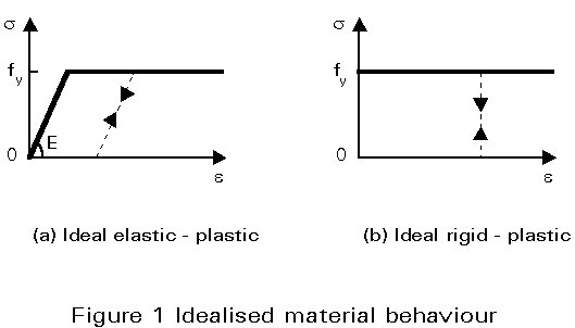
The behaviour of carbon and low-alloy steel grades is usually represented by means of the ideal elastic-plastic stress-strain relationship shown in Figure 1a. For situations in which there is little elastic deformation, the ideal rigid-plastic model, shown in Figure 1b, adequately represents the material behaviour (the plateau represents the yield stress fy).
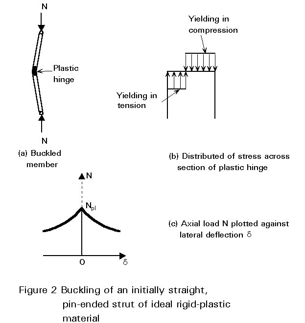
Rigid-plastic behaviour assumes that neither lateral nor axial deformation takes place at low values of the axial load, N. Each cross-section experiences the same uniformly distributed compressive stress s = N/A and axial deformation is only possible when s reaches the yield stress fy; the corresponding axial load is termed the "squash load" and is given as :
Npl = A fy (1)
At this stage, any slight disturbance results in a lateral displacement giving rise to an additional bending moment. The member collapses with the deformation confined to a plastic hinge at some point along its length (Figure 2a); the stress distribution is bi-rectangular (Figure 2b), plastic deformation occurring in tension as well as compression. The buckled member remains in equilibrium provided N becomes lower than the squash load; in this case the compressive yield stress is no longer attained over the entire cross-section. The larger the lateral displacement, the larger the bending moment at the plastic hinge and thus the smaller the coincident axial load (Figure 2c).
As long as the elastic critical buckling load Ncr is smaller than the squash load Np1, the member remains straight and undergoes elastic axial deformation. When collapse occurs by elastic critical bending at a load N = Ncr, the resulting lateral deflection induces bending moments, that increase the stress at the concave side of the member and decrease it at the convex side. Yielding occurs, in the central part of the member, in compression and more rarely in tension.
When, on the other hand, the squash load Np1 is reached prior to the elastic critical buckling load Ncr, the behaviour is similar to that of the rigid-plastic strut, but with additional elastic axial and bending deformations. The failure load, in this case, is the squash load, Np1.
Elastic column buckling analysis emphasizes the influence of the slenderness, l =l/i, on the resistance; l is the strut buckling length (see Lecture 7.7), equal to the member length when the strut is pin-ended, and ![]() is the radius of gyration for the plane of flexural buckling considered. Plotting the average compressive stress, sk, at failure against the slenderness, l, gives a clear understanding of the relationship between the two types of behaviour (see Figure 3a). Elastic critical buckling is represented by the hyperbola s =scr = p2E/l2; its range of application is limited by the plastic squashing line s =fy. The two lines intersect at the slenderness value l1, termed reference slenderness, such that p2E/l12
=fy, which gives:
is the radius of gyration for the plane of flexural buckling considered. Plotting the average compressive stress, sk, at failure against the slenderness, l, gives a clear understanding of the relationship between the two types of behaviour (see Figure 3a). Elastic critical buckling is represented by the hyperbola s =scr = p2E/l2; its range of application is limited by the plastic squashing line s =fy. The two lines intersect at the slenderness value l1, termed reference slenderness, such that p2E/l12
=fy, which gives:
l1 = p ![]() (2)
(2)
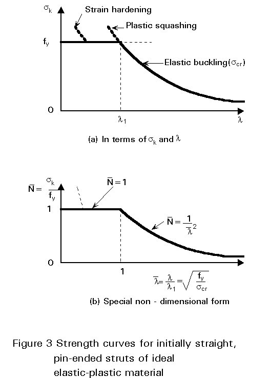
Thus, collapse occurs by plastic squashing for l< l1, and by elastic buckling when l > l1. Usually the curve is drawn in a normalized form (Figure 3b), where ![]() is plotted against
is plotted against
![]() = l /l1, so that plastic squashing (
= l /l1, so that plastic squashing (![]() = 1) and elastic buckling
= 1) and elastic buckling ![]() intersect at
intersect at ![]() .
.
The actual stress-strain diagram of some structural steel grades is shown in Figure 4.
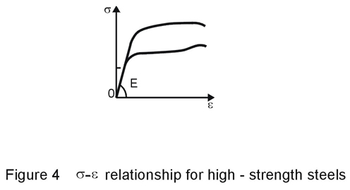
Compared to the ideal elastic-plastic behaviour, three main differences are evident:
a) at high strains, the material may undergo strain-hardening.
b) the strain is limited to a maximum value, at which point the material breaks.
c) there may be no clearly defined yield point.
As buckling does not require large material ductility, point (b) is usually irrelevant.
Strain-hardening does not affect the first yield but contributes to an increase in the collapse load. This effect is obviously more marked at low slenderness values, where plastic deformation is predominant, and should raise the corresponding portion of the column strength curve (Figure 3a). In practice, the beneficial effect due to strain-hardening is neglected.
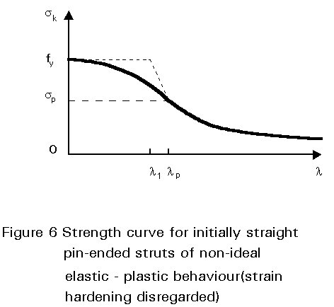
Different steel alloys exhibit different stress-strain behaviours; high strength steels, in particular, do not usually have a clearly defined yield point and can be classified as follows:
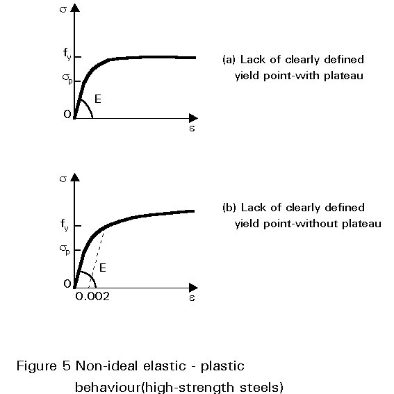
The strut resistance curve becomes that shown in Figure 6 (strain-hardening has been disregarded).
The previous sections considered highly idealized strut models which do not represent the real responses of compression members, because of the unavoidable imperfections resulting from any manufacturing process. The following sections consider the effect of these imperfections on real structural response; the imperfections are firstly considered independently, and then in combination as would arise in an actual structure.
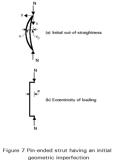
Geometric imperfections correspond either to lack of straightness of the structural member (Figure 7a), or to eccentricities of the applied load (Figure 7b).
Buckling is characterised by a predominant displacement field associated with the buckled shape of the member; any initial deflection will, therefore, affect instability as will any eccentricity of the applied loading. The resulting destabilizing secondary effects reduce the load-carrying resistance, compared to that of a perfect member.
Because these imperfections are in the range of normal fabrication tolerances, they are generally not visible and cannot be quantified precisely beforehand; they must, however, be taken into account in the design in an appropriate way.
The two types of geometric imperfections shown in Figure 7, are now considered:
The initial out-of-straightness of a pin-ended strut (Figure 7a) is also termed "initial crookedness" or "initial curvature". It causes a secondary bending moment as soon as any compression load is applied, which in turn leads to further bending deflection and a growth in the amplitude of the lever arm of the external end compression forces; this results in geometrically non-linear behaviour. A stable deflected shape is possible as long as the external moment, i.e. the product of the load and the lateral deflection, does not exceed the internal moment resistance of any section. Column buckling in the presence of an initial curvature is therefore by divergence of equilibrium, as opposed to the bifurcation type of instability typical of ideal compression members.
Any cross-section of the strut experiences combined bending and axial load, whatever the amount of loading. Because geometric linearity is no longer valid (equilibrium requires consideration of the deflected shape), the effects of bending and axial load cannot be simply superimposed in order to describe the actual response.
For some elementary loading and support conditions, a direct procedure can be used, based on integration of the appropriate equilibrium differential equation describing the deflected shape. The fundamental equilibrium equation for a strut having an initial elastic curvature vo(x) in the buckling plane, is as follows (see Figure 7a):
![]() (3)
(3)
where v(x) is the additional buckling deflection associated with the axial load N. Because the first buckling mode of a pin-ended strut is a sine half-wave, the initial curvature is similarly chosen; it is then easy to show that the amplitude of the total deflection vt at the critical section (at x = 0,5 L in this case) is as follows:
vt = vo/(1 - N/Ncr) (4)
where Ncr = p2EIz/L2 is the critical column buckling load. The axial load, therefore, magnifies the initial out-of-straightness and the first-order bending moment Nvo by an amplification factor 1/(1 - N/Ncr):
M = Nvt = Nvo/(1 - N/Ncr) (5)
Figure 8 (curve O´AB) plots the axial load N against the total lateral deflection vt in the buckling plane. The deflection tends to infinity as N approaches the elastic critical load Ncr, while an infinite tension load would be necessary to straighten the strut.
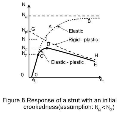
The distribution of bending moment along the member increases with the lateral deflection. Bending moment and stresses are the greatest at the critical sections; on the concave side of the strut, compressive stresses due to axial load and bending moment superimpose and the strut experiences the greatest stress. First yield will occur at this point as the axial load is steadily increased; the value of N corresponding to first yielding, termed Ny, constitutes the limit of validity C of the elastic response O'AB (Figure 8).
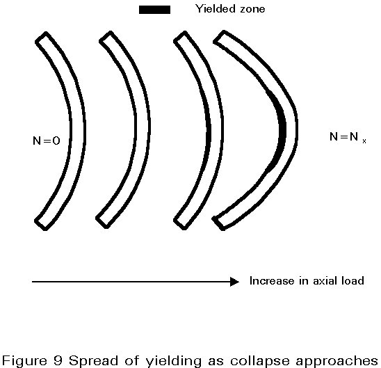
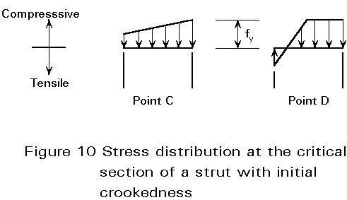
Any further increase of N above Ny results in a spreading of yielding, both along the strut and into the cross-section (Figure 9). This results in a further degradation of the strut stiffness, such that a maximum load NK is attained, at which the strut fails (point D in Figure 8). The ultimate load carrying resistance is hence a function of two sources of flexural stiffness deterioration: the axial load (instability) and the spread of yielding (plasticity). The stress distributions across the strut cross-section at stages C and D are shown in Figure 10. Usually the concave side of the strut does not yield in tension at collapse.
The post-collapse behaviour DE is asymptotic to the rigid-plastic response GH (see Figure 2c). The latter is plotted in Figure 8, assuming that Npl < Ncr. Obviously the yield load Ny and the ultimate load NK have Ncr and Npl as upper bounds (one may indeed have Ncr > Npl or Ncr < Npl). In any case the ultimate load will never exceed the load Ni where both elastic and rigid-plastic responses intersect (point I). How close Ny and Nu are to Ncr and Npl depends on the slenderness of the strut and on the amplitude of the initial crookedness.
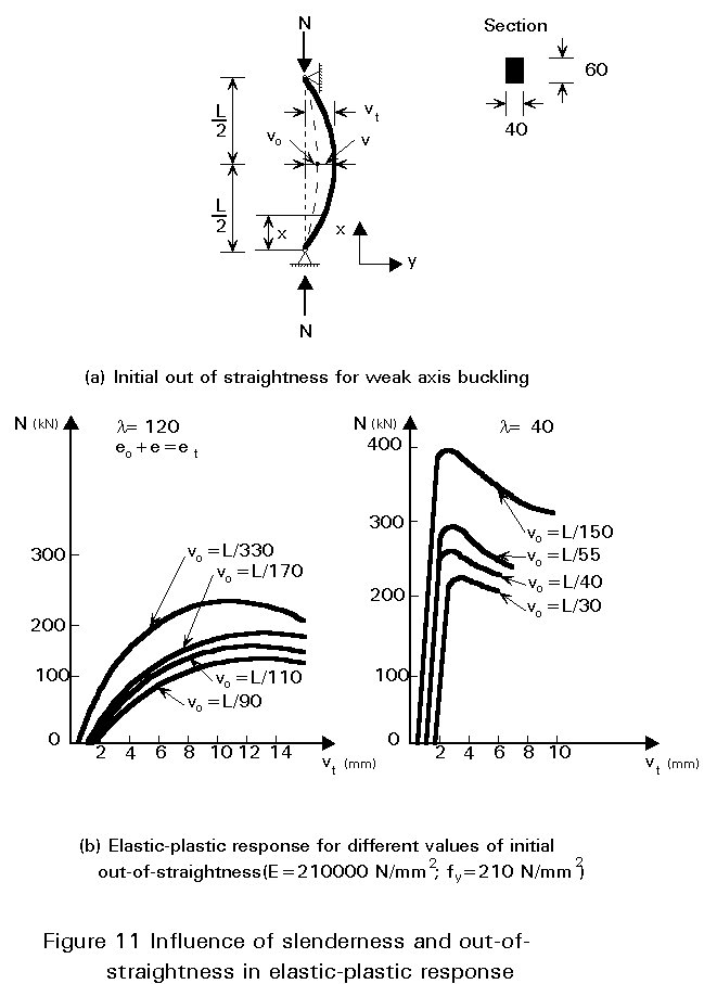
The influence of both slenderness and lack-of-straightness on the elastic-plastic response is shown in Figure 11 for a rectangular steel section; the following conclusions are drawn:
a) Whatever the slenderness, the larger the initial crookedness, the smaller the ultimate load.
b) For a specified value of the relative out-of-straightness (vo/L), the smaller the slenderness, the steeper the elastic behaviour.
c) The post-collapse behaviour is a slowly descending curve for slender struts with any tolerable initial out-of-straightness.
d) For stocky members, the post-collapse response is still a descending curve, the steepness of which becomes greater as the initial crookedness decreases.
Provided the initial curvature is known beforehand, (if, for instance, it can be measured), it is possible to construct an ultimate resistance curve from the calculated collapse loads. Such a curve is of the form (a) shown in Figure 12. If the initial curvature is similar to the buckling mode, the resistance curve will start from sK=fy for vanishing slenderness and lie below that for initially straight struts, though approaching the latter, as slenderness increases. Indeed, for very stocky members, the influence of initial curvature is negligible and the plastic squash load is still the ultimate load. On the other hand, very slender struts exhibit an elastic critical load Ncr much lower that the squash load Npl; in such cases, the point C of Figure 8 may be well up the elastic response curve, so that the collapse load is close to the elastic critical load. The influence of initial crookedness is especially marked for intermediate slenderness ratios; the greatest loss of resistance (strength) occurs in the vicinity of l1, where plastic squashing and elastic buckling are nearly coincident and therefore interact the most.
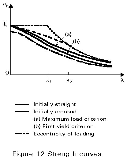
If the collapse criterion is chosen as the first yield load Ny instead of the maximum load NK, the strength curve will be lower but of similar shape (curve b - Figure 12).
An end compressive load, N, applied with an eccentricity, vo, to an initially straight pin-ended strut (Figure 7b) will induce a first-order bending moment in the strut which will begin to deflect laterally in a similar manner to the initially crooked strut analysed earlier.
The differential equilibrium equation in this case, is as follows:
![]() (6)
(6)
The sole deviation from Equation (3) is that the initial imperfection vo is not a function of x. From the integration of Equation (6) it can be seen that the first-order bending moment M0 = N vo is amplified by a factor = ![]() .
.
The amplification factors associated with the initial sine crookedness and the loading eccentricity are close to each other for the range of N/Ncr values encountered in practice. Therefore, the load-deflection response for an eccentrically compressed initially straight strut is similar to that plotted in Figure 8, except that the response curve starts at the origin of the axes.
Unlike the initial curvature, which is strongly dependent on the strut length, the loading eccentricity is more related to the section size. In addition, first-order bending is constant over the entire member length so that bending effects are likely to make the ultimate strength of very stocky members lower than the plastic squash load, giving, therefore, the form of strength curve (c) plotted in Figure 12.
Structural rolled steel shapes and plates have residual stresses locked in them, due to uneven cooling after rolling; so also do welded built-up members as the consequence of local heat input and cooling of the weld material and the surrounding parent material. Similarly residual stresses exist in cold-formed sections, due to the large plastic deformations that have occurred during the forming process. For non-loaded members in equilibrium, the residual stresses must be an autostress state.
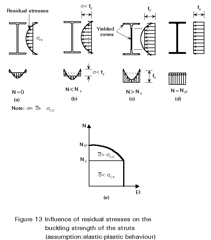
The distribution and the magnitude of the residual stresses depend on many parameters, (see Lectures 7.5.1 and 7.5.2); in rolled and welded built-up sections of regular size, for instance, tensile residual stresses occur in the regions that are the last to cool down; they are counterbalanced by compressive stresses in the remaining part of the cross-section. Provided the wall thickness of these sections is not too large, it can usually be assumed that the magnitude of the residual stresses is constant over the wall thickness. A typical residual stress distribution for I-sections is plotted in Figure 13a.
Residual stresses result in early first yielding; this occurs before the average applied compressive stress ![]() attains the material yield stress fy. In fact onset of yielding is achieved in the fibre(s) with peak compressive residual stress sr,c at a load Ny for which
attains the material yield stress fy. In fact onset of yielding is achieved in the fibre(s) with peak compressive residual stress sr,c at a load Ny for which
![]() p + sr,c
= fy .
p + sr,c
= fy .
Up to this loading level, the behaviour is elastic; the uniformly distributed applied stress
![]() £
£
![]() p
superimposes on the residual stress distribution sr,c. Any additional loading beyond Ny induces the spread of yielding in the cross-section. Yielded fibres have a reduced stiffness compared to the remaining elastic ones, because they experience specific strains e larger than the yield strain ey. Consequently the flexural stiffness of the strut is constant up to the first yielding; it then decreases progressively for larger loading (Figure 13e) to vanish entirely at the plastic squash load (under the assumption that strain-hardening is disregarded). The entire cross-section yields when the average applied stress equals the material yield stress. The average applied axial stress
p
superimposes on the residual stress distribution sr,c. Any additional loading beyond Ny induces the spread of yielding in the cross-section. Yielded fibres have a reduced stiffness compared to the remaining elastic ones, because they experience specific strains e larger than the yield strain ey. Consequently the flexural stiffness of the strut is constant up to the first yielding; it then decreases progressively for larger loading (Figure 13e) to vanish entirely at the plastic squash load (under the assumption that strain-hardening is disregarded). The entire cross-section yields when the average applied stress equals the material yield stress. The average applied axial stress
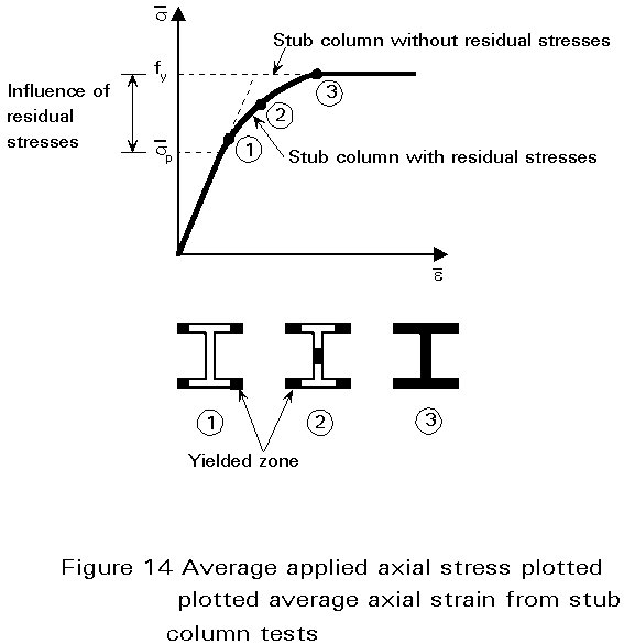
![]() K is plotted against average axial strain
K is plotted against average axial strain ![]() (shortening/length) in Figure 14. This graph is similar to the s - e curve for steel with no clearly defined yield point but with a yield plateau (Figure 5a). It behaves as if the compressed stub column having residual stresses was made with a fictitious steel having a stress-strain relationship and a limit of proportionality sp which is different to the material limit of proportionality because of the presence of residual stresses.
(shortening/length) in Figure 14. This graph is similar to the s - e curve for steel with no clearly defined yield point but with a yield plateau (Figure 5a). It behaves as if the compressed stub column having residual stresses was made with a fictitious steel having a stress-strain relationship and a limit of proportionality sp which is different to the material limit of proportionality because of the presence of residual stresses.
The collapse load of a stub column is, therefore, not affected by residual stresses, and still equals the plastic squash load. Similarly, very slender struts, whose critical buckling stress does not exceed
![]() p, buckle elastically and are not affected by residual stresses. The effect of residual stresses is most marked in the range of intermediate slenderness; in this case premature yielding reduces the bending stiffness and the struts buckle inelastically at a load below both the elastic critical buckling load and the plastic squash load. The corresponding resistance (strength) curve is of the form shown in Figure 6; it must, however, be kept in mind that the coordinates represent the average applied stress and axial strain respectively, i.e.
p, buckle elastically and are not affected by residual stresses. The effect of residual stresses is most marked in the range of intermediate slenderness; in this case premature yielding reduces the bending stiffness and the struts buckle inelastically at a load below both the elastic critical buckling load and the plastic squash load. The corresponding resistance (strength) curve is of the form shown in Figure 6; it must, however, be kept in mind that the coordinates represent the average applied stress and axial strain respectively, i.e.
![]() p is substituted for sp.
p is substituted for sp.
The greatest loss of strength resulting from the effect of residual stresses is again at l » l1.
All the effects analysed separately above occur simultaneously in practice. Initial curvature, initial eccentricity of loading, residual stresses and lack of a clearly defined yield point lower the column resistance curve for all or part of the slenderness range. On the other hand, strain hardening is likely to raise the resistance curve, although only the range of low slenderness values is affected. The beneficial effect so obtained usually does more than compensate for the loss of resistance due to accidental eccentricities; in any case the column strength curve is considered as having a cut-off at ![]() , so that some strength reserve is ignored.
, so that some strength reserve is ignored.
Tests and numerical investigation demonstrate clearly that:
a) The separate influences of residual stresses and initial crookedness cannot be simply added to get a good assessment of their combined influence on the ultimate resistance.
b) For intermediate slenderness ratios and low residual stresses, the combined influence is normally less than the sum of the parts, whereas for other cases it can be more.
c) Variations in the shape of the residual stress pattern result in differences in column resistance; these are, however, smaller for initially crooked columns than for initially straight ones.
d) The influence of both lack-of-straightness and residual stresses is higher for columns with intermediate slenderness ratios. In this range squash loads and critical loads are nearly coincident; the ultimate resistance depends on the flexural stiffness, the material yield strength, the amplitude and distribution of residual stresses and the initial crookedness. The interaction between both these latter imperfections can result in a large drop in ultimate resistance, compared to the axial load resistance of the perfect column.
Because all the deviations from the ideal strut and material are subject to statistical variations, it is impossible to predict accurately the real resistance of a specified standard strut shape. For design purposes, lower bound resistance curves are used which ensure, to a specified probability, that the calculated buckling loads do not overestimate the actual ultimate resistance.