ESDEP WG 6
APPLIED STABILITY
To extend and generalise to other instability phenomena the conclusions drawn in Lecture 6.6.1 on column buckling.
Lecture 6.3: Elastic Instability Modes
Lecture 6.6.1: Buckling of Real Structural Elements I
Lecture 7.3: Local Buckling
Lectures 7.5: Columns
Lectures 7.10: Beam Columns
Lectures 8: Plates and Shells
Lectures 9: Thin-Walled Construction
Plate buckling and types of buckling involving torsional deformation are considered, as is the basic type of shell buckling, i.e. the case of an axially compressed cylinder. For each type of buckling a description of the basic phenomena is given; the behaviour is analysed in terms of the pre-buckling, post-buckling and collapse behaviour, and the governing geometric parameters are identified. Comment is also briefly made on how members can be strengthened to prevent buckling failures.
The influence of imperfections, material plasticity and strain hardening on ultimate resistance, has been reviewed in detail in the previous Lecture 6.6.1 with reference to column flexural buckling. This is the form of member instability that has been most studied and an almost complete understanding of the phenomenon has been achieved.
Most of the conclusions drawn in the previous lecture are still valid, in general terms, for other forms of instability. These forms are, however, characterised by different kinds of deformations, so that the nature of the imperfections that most affect the ultimate resistance are different to flexural buckling; to gain an understanding of the real buckling resistance of columns, therefore, the effect of imperfections on these different forms of instability must be analysed.
Plate buckling is first examined because it often occurs in the form of local buckling, i.e. buckling of section-plate components; moreover, it helps to understand torsional column buckling, where buckling occurs with a twist of the cross-section only. Column flexural-torsional buckling is then examined; this is well named because bending and torsional deformations are always linked together as in the lateral-torsional buckling of beams. Buckling of shells is also considered; this very complex phenomenon is illustrated by reference to the basic case of an axially loaded cylindrical shell.
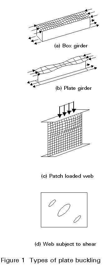
Plate buckling occurs where thin-walled sections experience compressive stresses. This phenomenon is quite similar to column buckling; it involves, however, elements of the member cross-section rather than displacement of the section as a whole. Compressive stresses may arise not only from compressive axial load but also from bending of the member, and even from patch loads (Figures 1a, 1b, and 1c). Local buckling may also occur in plates subject to shear (Figure 1d), because shear results in compressive and tensile principal stresses
Cold-formed sections and thin plated sections are the most sensitive to local buckling.
The elastic buckling modes and corresponding critical stresses of compressed plates are derived from the small deflected plate equations; their analysis has been carried out in Lecture 6.3.
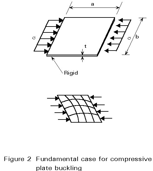
It has long been recognised that the critical buckling load of a plate is not a satisfactory measure of the actual plate resistance. Indeed, as soon as the plate tends to buckle, out-of-plane deflections result in membrane forces due to the stretching of the mid-plane of the plate. To understand this behaviour let us consider an initially flat rectangular plate, having all edges either simply supported, or clamped, and loaded in uniform uniaxial compression. Let us assume, in addition, that the aspect ratio is such that the plate will buckle in a single half-wave mode (Figure 2). For the purpose of this analysis the plate can be replaced by a system of strips in both orthogonal directions; the longitudinal strips are compressed and are thus liable to buckle. Below the elastic critical plate buckling load, all the longitudinal strips are straight because the plate remains flat; they maintain their initial stiffness and experience equal compression stress. Once the plate buckles, the longitudinal strips close to the edge are constrained to remain straight while those away from these edges are more prone to buckling; in other words the first ones retain their axial stiffness while the latter lose a part of their initial stiffness.
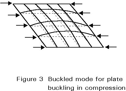
The plate buckling causes an increase in length of the transverse strips because the longitudinal edges are restrained against free shortening of the plate in the transverse direction; this causes tensile membrane forces in the transverse strips, that exert a stabilising effect on the longitudinal strips (Figure 3). This explains why stable equilibrium states can be reached by the plate beyond the elastic critical plate buckling load, with the result that large post-buckling resistance may be possible provided the material does not yield prematurely. This is the fundamental difference between plate behaviour and column buckling, which is not able to exhibit such a reserve of resistance.
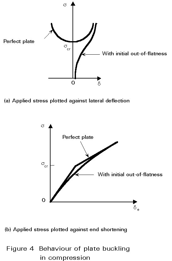
When the plate buckles, in-plane and out-of-plane displacements interact, resulting in a non-linear behaviour. The plate behaviour, in the large deflection regime, can only be deduced from both the compatibility and equilibrium non-linear plate equations. It is represented, in Figure 4, by the plot of the mean applied stress against plate lateral deflection, and end shortening; the latter plot is bi-linear when the plate is initially perfectly flat, and the slope represents the axial stiffness of the plate; the post-buckling axial stiffness depends on the in-plane restraints offered by the boundary but varies usually from 40 to 75% of the initial stiffness. The larger the restraints against in-plane displacements of the boundary (primarily of the longitudinal edges), the larger the stabilising effect resulting from the membrane forces, and the larger the possible post-buckling reserve of resistance.
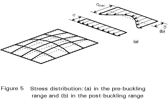
The ultimate load is finally reached when the stiffness of the plate has sufficiently deteriorated due to material yielding. Plate buckling results, as mentioned above, in a non-uniform membrane stress distribution across the plate width with peak stresses at the longitudinal edges (Figure 5). Yielding will, therefore, occur first at these edges and spread rapidly until collapse is reached.
The post-buckling resistance is exhibited especially by plates having slender proportions and which, to a large extent, behave elastically. The ultimate load, in this case, may amount to several times the elastic critical load. For plates of low and intermediate slenderness, plate behaviour is mainly affected by material plasticity; indeed the more stocky the plate, the more yielding will tend to precede plate buckling with the result that the ultimate resistance may be even lower than the elastic critical load.
Plate manufacturing and fabrication processes result in unavoidable geometric imperfections and residual stresses. In most cases, both have an effect on the pre- and post-buckling behaviour.
The fundamental geometric imperfection is the initial out-of-flatness, which, as would be expected, significantly affects plate buckling. Due to lack of flatness, the out-of-plane plate deformations increase from the onset of loading. The magnitude of out-of-flatness influences the load-deflection plate response; however, as long as the response is elastic, plates with any level of imperfection will approach the post-buckling behaviour of ideally flat plates (Figure 4a). In the load-end shortening plot, the effect of out-of-flatness is to round off the "knee" at the critical stress (Figure 4b). Not only the magnitude but also the pattern of the initial out-of-flatness may influence the plate response; the more similar the buckling mode is to this pattern, the more plate buckling occurs and proceeds smoothly. On the other hand, any out-of-flatness which differs from the buckling mode tends to delay plate buckling; however, when this occurs, it happens suddenly in a way termed 'snap-through'. Because of the random nature of the out-of-flatness pattern (unknown at the design stage), it is usually conservatively assumed that the imperfection is close to the first plate buckling mode.
The plate residual stresses also tend to reduce the initial axial stiffness and affect the yielding process.
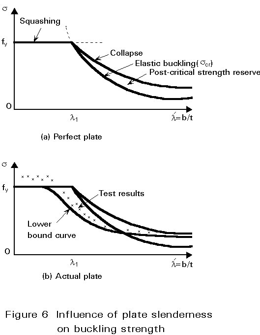
Plate slenderness is the geometric parameter governing the plate ultimate resistance. The latter is generally represented (Figure 6a) by a plot of the mean applied stress at failure against the slenderness parameter l¢ =b/t, "b" being the plate width in the direction perpendicular to the compression.
An elastic initially flat plate should buckle for a critical stress:
s
cr = ks [p2E/12 (1 - n2)] (1/l¢)2 (1)where ks is the plate buckling coefficient and n the Poisson ratio. Due to material plasticity, the squash load provides a limit to plate resistance and constitutes a cut-off limit to the elastic buckling curve. As explained above, however, the ultimate average stress of a slender plate, i.e. a plate for which scr is lower than the yield stress fy, exceeds the elastic critical stress as a result of the post-buckling resistance; the ultimate stress curve thus lies higher than the critical stress curve. The transition between squashing and plate buckling occurs when scr = fy, that is for the following slenderness:
l
1¢ = pFor a simply supported long plate, subject to uniform compression, the buckling coefficient is roughly k =4; the corresponding value of
l1¢ = 1,9 ![]() amounts to between 56 and 46 for the usual steel grades S235 and S355. The value of the buckling coefficient k, for other cases, depends on the plate aspect ratio, the type of loading and the boundary conditions.
amounts to between 56 and 46 for the usual steel grades S235 and S355. The value of the buckling coefficient k, for other cases, depends on the plate aspect ratio, the type of loading and the boundary conditions.
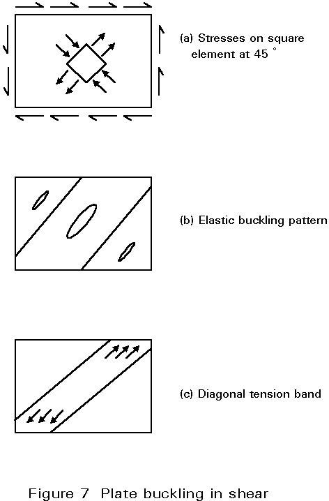
The existence of post-buckling resistance in a plate subject to shear can be physically explained as follows: a square element, the edges of which are oriented at 45° to the plate edges, experiences tensile stresses, s1, on two opposite edges and compressive stresses, s2, on the other two (Figure 7a); these compressive stresses can, therefore, induce plate buckling in the form of elongated bulges oriented in the direction of the tensile stresses (Figure 7b). The elastic critical shear stress, tcr, is given by an expression similar to scr; again tcr depends on the aspect ratio and the edge support conditions. Once the plate buckles in shear, the increase in compressive stresses is no longer possible while the initial axial stiffness of the plate, in the direction in which the tensile component acts, is still nearly fully available. Therefore, shear load increases are basically resisted by tensile stress increases and bulges consequently become narrower. The plate behaves as a series of strips in the tension direction and develops a so-called tension field (Figure 7c). This field rotates when the applied stress increases, to line up more closely with the plate diagonal; the ultimate shear load is reached when these strips yield. Here too, the in-plane restraints may appreciably influence the extent of the post-buckling reserve of resistance.
It can be concluded, therefore, that initial out-of-flatness, residual stresses and strain hardening all affect the behaviour and the ultimate resistance of plates; the effect is similar to that for column buckling, the sole but fundamental difference being that, at high slenderness, the plate resistance curve approaches the post-buckling curve rather than the critical buckling curve.
The above conclusions can be extended qualitatively to any portion of a plate which experiences compressive stresses; quantitatively it can be said that the amount of post-buckling resistance may vary appreciably with the type of loading and the kind of boundary conditions.
Similarly to column resistance curves, plate resistance curves are usually plotted as normalised coordinates (Figure 6b): the mean ultimate stress is divided by the material yield stress, while the normalised plate slenderness is defined, as for column buckling, in general terms:
![]() p =
Ö(fy/scr)
(3)
p =
Ö(fy/scr)
(3)
Using Equation (1), the normalised plate slenderness is as follows:
![]() p =
(b/t)(1,05/Ök)Öfy/E
(4)
p =
(b/t)(1,05/Ök)Öfy/E
(4)
Accordingly, ![]() p = 1 is the limit slenderness which corresponds to the transition between squashing and plate buckling. The normalised slenderness includes the usual plate slenderness, l¢ = b/t, but is affected, through k, by the aspect ratio of the plate, the type of loading and the boundary conditions. To account for actual imperfections, plate resistance curves ought be lower bounds of the available test results.
p = 1 is the limit slenderness which corresponds to the transition between squashing and plate buckling. The normalised slenderness includes the usual plate slenderness, l¢ = b/t, but is affected, through k, by the aspect ratio of the plate, the type of loading and the boundary conditions. To account for actual imperfections, plate resistance curves ought be lower bounds of the available test results.
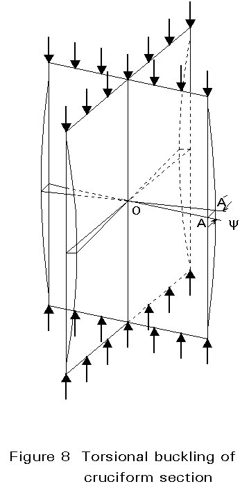
Instability due to torsional buckling can only arise in special circumstances. This buckling type is illustrated by means of a compressed strut composed of four identical outstands, giving a cruciform section (Figure 8); each outstand is a flat thin plate, liable to buckle because of the compression loading. If such a plate was simply supported along the column axis, it would buckle so that any line OA of the outstand, perpendicular to the longitudinal edges, would remain approximately straight, though rotating about point 0. Because the outstands are identical, they should each buckle at the same value of applied stress. It is thus possible to find a form of buckling in which any cross-section of the cruciform strut does not distort, but rotates about 0. The four outstands continue to meet at right angles so that the fact that they are joined rigidly along a common edge is not significant. This form of buckling, where the strut axis remains straight but sections rotate is termed "torsional buckling".
Because torsion is involved in such a buckling process, the elastic critical buckling stress depends partly on the Saint-Venant torsional rigidity and on the warping rigidity. In addition, the end torsional and warping restraints must be reflected in the numerical factors used.
Torsional buckling can only properly occur when the shear centre and centroid of the cross-section are coincident, i.e, only in symmetrical sections; thin-walled components will also obviously favour this form of buckling. Because flexural buckling (usually termed column buckling) is still possible, each form must be examined to determine which gives the lower critical stress.
As for flexural buckling, the elastic critical torsional buckling load is not an adequate measure of the carrying resistance. One must again allow for geometric imperfections, residual stresses and for the effects of material plasticity and strain hardening. Regarding the initial geometric imperfections, the initial twist of the strut and the lack of flatness of the section components are understandably the most significant. Unlike flexural buckling, for which much information is available, the ultimate resistance associated with torsional buckling cannot be assessed very accurately because of the lack of sufficiently documented experiments and corresponding test results. Allowance for geometric imperfections, residual stresses, material plasticity and strain hardening, parameters which reduce the ultimate load below the elastic critical one, is based more on engineering judgement than on a fully justified procedure. It is generally accepted that the procedure used for flexural buckling can be extended to torsional buckling by assuming that the reduction in resistance due to imperfections and plasticity are similar in both cases, when referring to normalised coordinates. The normalised slenderness is consistently defined as follows:
![]() T =
Ö(fy/scr,T)
(5)
T =
Ö(fy/scr,T)
(5)
where scr,T is the elastic critical torsional buckling stress.
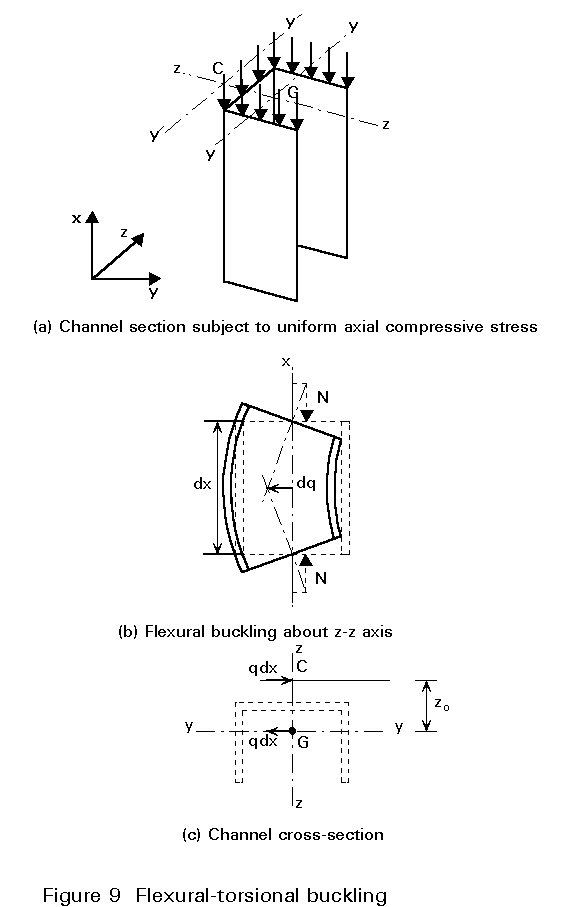
Flexural and torsional displacements are combined when the shear centre and centroid of the section are not coincident. This results in a reduction of the critical buckling load compared to that associated with flexural buckling. This phenomenon is particularly important for angles and channel sections.
To illustrate this form of buckling, a channel section is considered subject to a uniaxial compressive load at the centroid, so that the end sections experience a uniform applied stress (Figure 9a). The section is assumed to be proportioned so that the second moment of inertia, Iyy, about yy axis, is larger than that about zz axis; the flexural buckling about the zz axis is thus governing (Figure 9b). As soon as the strut tends to buckle in the direction yy, i.e. by bending about the zz axis, its deflection v(x) produces a bending moment M(x) = Nv(x), giving rise to an associated shear, V = dM/dx = N(dv(x)/dx). Everything happens as if the strut was subject to transverse distributed forces q=-dV(x)/dx =-N(d2v(x)/dx2), acting in the plane yy containing the centroid G, and not in the plane zz containing the shear centre C (Figure 9c). Therefore bending about the zz axis and the corresponding shear induce a torque moment dMt = qzo dx, where zo is the distance between the centroid and the shear centre. This means that purely flexural buckling in the yy plane is impossible, because bending and torque deformations are inevitably coupled. This form of buckling is termed "flexural-torsional buckling".
Flexural-torsional buckling is governed by three equilibrium differential equations containing the derivatives of the three functions: displacements v and w in the yy and zz planes and the twist y. The flexural-torsional buckling load thus depends on the usual boundary conditions for v and w at the ends (pin-ended or clamped) and on the twist and warping restraints on y.
In the usual case of a pin-ended strut, which is fully free to warp, i.e.v=v"=0,w=w"=0 and y = y" = 0 at the ends, the critical flexural-torsional buckling stress is as follows:
s
cr,FT={scr,zz + scr,T ± Ö{(scr,T - scr,zz)2 + scr,zz . scr,T (zo/ro)2 ]} / {2[1 - (zo/ro)2]} (6)where yo and zo are the coordinates of the shear centre and ![]() . It is apparent that this value is always lower than the flexural buckling stress, scr,zz about the zz axis and the torsional buckling stress, scr,T. It should also be checked if it is also lower than the flexural buckling load scr,yy about the yy axis which is the other root of the characteristic equation.
. It is apparent that this value is always lower than the flexural buckling stress, scr,zz about the zz axis and the torsional buckling stress, scr,T. It should also be checked if it is also lower than the flexural buckling load scr,yy about the yy axis which is the other root of the characteristic equation.
It should be noted that for a doubly symmetrical section (zo=yo=ro=0), the roots are:
s
cr = scr,yy = scr,zzand that the lowest of the three values - scr,T, scr,zz and scr,yy - is the governing one.
Flexural-torsional buckling implies deformations due to both column flexural and column torsional buckling. The associated ultimate resistance will thus be affected by all types of imperfections, which affect these two basic phenomena.
As in the case of column torsional buckling, there is a lack of information on the loss of flexural-torsional buckling strength due to imperfections, residual stress and material plasticity; again, the procedure used for flexural buckling is generalised by using the same normalised strength curves, assuming the normalised slenderness is defined as:
![]() FT =
Ö(fy/scr,FT)
(7)
FT =
Ö(fy/scr,FT)
(7)
When a beam is subject to major axis bending, either due to end moments or, more typically, due to transverse loads, one of the flanges, along with an adjacent portion of web, is compressed and is, therefore, prone to buckling.
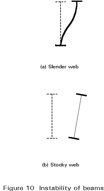
Buckling of the compression flange in the web plane is normally prevented by the web, because of the large rigidity of the latter in its own plane; buckling of the flange in the flange plane is, therefore, most often critical because the web provides only limited restraint in this direction. When the web is very slender, it is likely to be distorted so that the restraint is negligible and lateral-torsional buckling is very close to flange buckling by bending about the weak axis of the cross-section (Figure 10a). A stocky web, however, behaves roughly as a rigid plate element and lateral-torsional buckling causes the section to twist (Figure 10b). Because of the rotation of the principal axes compared to their initial direction, the resulting deformation is a combination of torsion and lateral bending.
For a perfect beam, loaded in the strong direction of bending, lateral-torsional buckling occurs for a critical value of the maximum bending moment, or the maximum compressive stress. This value is affected by several factors: the moment distribution along the beam (shape of the bending moment diagram), the boundary conditions (bending, torque and warping restraints), the level of application of the transverse loads, and the possible non-symmetry of the cross-section. As this buckling involves torsion and weak-axis bending, the critical bending moment will be expressed in terms of the beam length L, the torsional and warping rigidity, GJ and EIw respectively, and the bending stiffness about the weak axis, EIz.
The elastic critical bending moment of an I or H section, for example, is as follows:
 .
C1
(8)
.
C1
(8)
where C1 and C2 are coefficients allowing for the influence of the aforementioned factors and zg is the distance from the shear centre to the point of application of the transverse loads. The elastic critical lateral-torsional buckling stress is as follows:
s
cr,LT = Mcr,LT/ Wy (9)where Wy is the elastic section modulus for bending about the strong axis.
In addition to material plasticity and residual stresses, geometric imperfections cause a loss in resistance compared to the elastic critical load. Any imperfection which is liable to trigger off torsion and/or lateral bending is obviously of concern. A recent statistical evaluation of test results, carried out when preparing background documents for Eurocode 3 [1], has demonstrated that the format of the ultimate resistance curves for flexural column buckling is quite appropriate to represent the lateral-torsional buckling response, provided the curve parameters are suitably calibrated. As for the previous forms of buckling, the normalised slenderness for lateral-torsional buckling is defined as:
![]() LT =
Ö(fy/scr,LT)
(10)
LT =
Ö(fy/scr,LT)
(10)
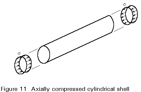
Shell buckling is probably the most complex instability phenomenon. Similar to plate buckling, it involves the cross-sectional shape rather than displacement of the section as a whole. Compressive stresses, as before, can arise from compressive axial load, bending and locally applied concentrated loads. In addition, however, shells can also be subject to internal or external pressures (pipes, silos, tanks, off-shore jacket legs, etc.).
The simplest case to analyse is the axially compressed cylindrical shell (Figure 11); the elastic critical buckling stress is as follows:
s
cr = [1/where t is the wall thickness, and r the radius of the cylinder. This formula is well known in the format, scr = 0,605 Et/r, valid for steel cylinders.
The load-shortening behaviour shows a drastic loss of carrying resistance as soon as the critical buckling load is reached (Figure 12); when it buckles, the shell tends to a buckled shape, which is in equilibrium with an external compression load usually much lower than the critical load. This is a general characteristic of shells, whatever the type of shell and the type of loading; unlike plates, they are not able to exhibit any post-buckling reserve of resistance.
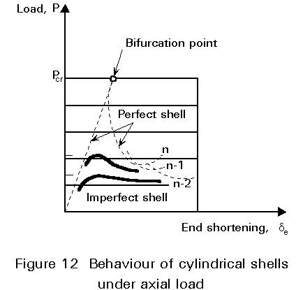
Even very small geometric imperfections cause a premature deviation from the load - displacement curve of the perfect shell usually giving a significant reduction in the load carrying resistance (Figure 12). Elastic critical loads cannot, therefore, be attained by real shells. The influence of imperfections on the ultimate load of shells is a very complex problem which has been extensively researched.
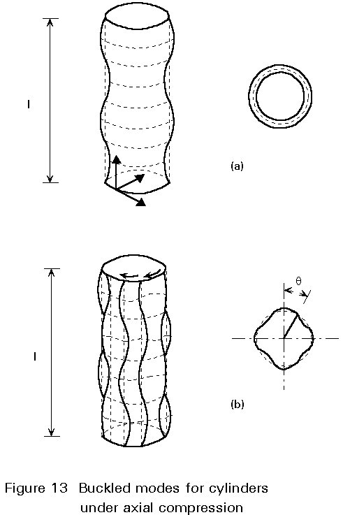
According to classical theory of shell buckling, the perfect cylindrical shell can buckle either axisymmetrically - with a succession of ring buckles - or in the form of a chessboard (Figure 13a, b); depending on the buckling circumstances, the shell may achieve a diamond-like post-buckling configuration. To account for imperfections, design rules traditionally use a knock-down factor, a, affecting the elastic critical shell buckling stress; values of a are derived from tests conducted on large scale models.
According to ECCS Recommendations [2], the value of this factor depends only on the slenderness, r/t, of the shell when imperfections are kept below a specified level. An additional partial safety factor, g, is applied in the case of cylindrical shells subject to meridional compression because of their especially unfavourable post-buckling behaviour.
The influence of the different types of imperfections on the ultimate resistance may vary greatly depending on the type of shell and on the type of loading. A normalised resistance curve is then defined by plotting the ratio s/fy against the normalised slenderness
![]() s
(
s
(![]() s =
Ö(fy/ascr),
similar to the approach used for column and plate resistance curves (Figure 14).
s =
Ö(fy/ascr),
similar to the approach used for column and plate resistance curves (Figure 14).
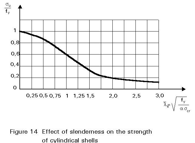
It should be noted that as ![]() s
increases, the resistance curve approaches the critical resistance value (reduced by the knock-down factor a).
s
increases, the resistance curve approaches the critical resistance value (reduced by the knock-down factor a).
The buckling resistance of a member, or of a section component, can be enhanced in a number of ways.
For a specified buckling form, a reduction of the slenderness ratio will result in a higher ultimate load. This will usually be achieved by increasing the cross-sectional dimensions; it can also be done by distributing the material differently about the centroid, while keeping the cross-section area constant; doing this, however, can change the section and/or member response, so that other buckling forms may become critical. In particular, a reduction in thickness of the cross-section components, in order to better distribute the material, often results in plate buckling governing the design.
Another way to improve the buckling resistance of a member is to provide it with better or additional restraints so that the buckling mode is modified. The elastic critical load of a pin-ended axially compressed column, for example, is increased by a factor 4 by providing a simple support at mid-height, so that the column buckles in a two half sine-wave mode. Similarly a simply supported beam, subject to bending about its major axis, is strengthened against lateral-torsional buckling by preventing bending and/or torque rotations at the end supports, or, more simply, by preventing the compression flange from any lateral displacement by means of adequate bracing. The ultimate resistance of a thin compressed plate can be appreciably improved by fitting longitudinal and possibly transverse stiffeners; provided these are stiff enough, the plate will buckle between the stiffeners, with a higher elastic critical stress. Stiffening of shell structures will similarly produce an increase in resistance.
Although the design resistance is related to the ultimate stress rather than to the elastic critical stress, the above comments can be qualitatively extended when referring to the ultimate carrying resistance.
When designing columns as parts of a frame, it would be convenient to isolate the columns from the remainder of the frame and to treat their design as separate problems. However most columns belonging to building frames experience bending actions applied at their ends, in addition to axial loads. These bending actions depend on the interaction between the column and its adjacent members -beams and columns. In some cases, the column will support the beams at failure; such situations occur when the beams are designed plastically and collapse while the column remains stable and elastic. There are other situations where the beams will support the column; that is especially the case when the beams are designed elastically and exhibit an elastic behaviour up to collapse, the latter being initiated by column instability.
Mostly columns in frames will appear as elastically restrained members subject to combined axial load and end moments. Therefore, they are termed beam-columns.
In most building frames, sway displacements are prevented by means of appropriate bracing systems, e.g. braces in the facades, staircases, reinforced concrete central core for utilities. Then the column ends are not likely to experience horizontal displacements. Stability of non-sway frames reduces itself to stability of the individual columns. Therefore there is the need for appropriate rules regarding the ultimate resistance of elastically restrained compression members subject to additional end moments.
Sometimes the horizontal forces, due to wind and possible earthquake, have to be resisted by bending actions in the whole frame, which exhibits horizontal displacements, usually increasing in magnitude from base to top. Then the columns deflect according to a S-shape, termed double-curvature bending. Horizontal displacements allow the gravity loads to develop additional bending moments, which are usually called secondary moments because they result from gravity loads acting on the deflected frame. The wording secondary is peculiarly not appropriate because the magnitude of the secondary bending moments can rarely be disregarded. Checking the frame stability by considering the stability of the individual columns appears thus more like a cooking recipe than a sound design procedure, but it does attempt to take into account the influence of second-order effects in the framed structure.
A full review of all these complex matters is beyond the scope of this present lecture. They are reviewed in more detail in Lectures 7 and in some other lectures where systems are especially considered.
| Buckling phenomenon | Type of member | Loading | Stiffness parameters | Slenderness ratio | Normalised slenderness |
|
Flexural |
Columns |
Axial compression |
EIy or EIz |
L/ix or L/iy |
|
|
Torsional |
Columns (open sections with double or point symmetry) |
Axial compression |
GJ, EIw |
- |
|
|
Flexural torsional |
Columns (open sections without double or point symmetry) |
Axial compression |
GJ, EIw EIy and/or EIz |
- |
|
|
Lateral torsional |
Beams |
Major axis bending |
GJ, EIw , EIz |
- |
|
|
Plate |
Thin plate or member component |
Compression or shear |
|
b/t |
|
|
Shell |
Cylindrical shell |
Axial compression |
- |
r/t |
|
[1] Eurocode 3: "Design of Steel Structures": ENV 1993-1-1: Part 1.1: General rules and rules for buildings, CEN, 1992.
[2] European Convention for Constructional Steelwork, Recommendations of Steel Shells, Publication 56, ECCS, 1988.