ESDEP WG 7
ELEMENTS
To describe the design rules in Eurocode 3 [1-3] for members with Class 4 sections.
Lectures 7: Elements
Lectures 8: Plates and Shells
Lectures 9: Thin-Walled Construction
For members with Class 4 sections [1] the effect of local plate buckling on the overall member behaviour has to be taken into account. The buckling is allowed for by using effective cross-sections which assume parts of the gross cross-section are inactive. The rules for the determination of the effective cross-section and the design checks required are given.
For members with Class 4 sections the effect of local buckling on global behaviour at the ultimate limit state is such that the elastic resistance, calculated on the assumption of yielding of the extreme fibres of the gross section (criteria for Class 3 sections), cannot be achieved.
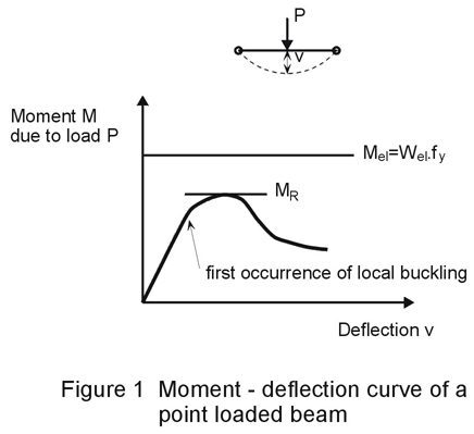
Figure 1 gives the moment deflection curve for a point loaded beam (Class 4). The reason for the reduction in strength is that local buckling occurs at an early stage in parts of the compression elements of the member; the stiffness of these parts in compression is thereby reduced and the stresses are distributed to the stiffer edges, see Figure 2.
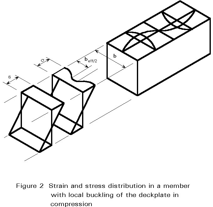
To allow for the reduction in strength the actual non linear distribution of stress is taken into account by a linear distribution of stress acting on a reduced "effective plate width" leaving an "effective hole" where the buckle occurs, Figure 2.
By applying this model an "effective cross-section" is defined for which the resistance is then calculated as for Class 3 sections (by limiting the stresses in the extreme fibres to the yield strength).
The effective widths beff are calculated on the basis of the Winter formula:
beff = r .b
where the reduction coefficient r is dependent on the plate slenderness ![]() p defined by linear plate bucking theory, as shown in Figure 3.
p defined by linear plate bucking theory, as shown in Figure 3.
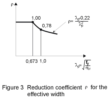
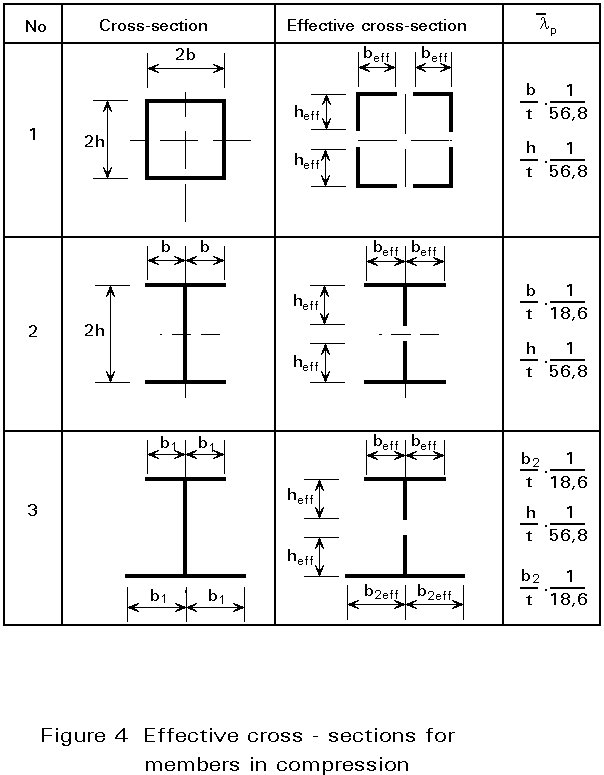
Figure 4 gives some examples of effective cross-sections for members in compression.
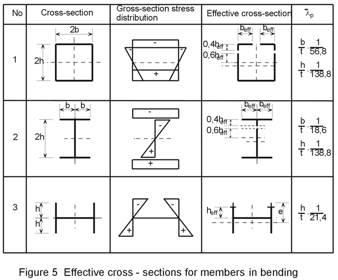
For members in bending test results have shown that the effective widths may be determined on the basis of stress distributions calculated using the gross section modulus, Wel , even though the formation of "effective holes" in the compression parts will shift the neutral axis of the effective cross-section; an interactive process is not, therefore, necessary.
Figure 5 gives some examples of effective cross-sections for members in bending.
As shown by the effective cross-sections 1 and 2, in Figure 4, the neutral axes of doubly-symmetrical cross-sections will not change with the formation of effective holes. Hence the compression load NSd that is central to the gross cross-sections will also be central to the effective cross-section.
The column buckling design check, therefore, is based on the non-dimensional slenderness
![]() =
= ![]() , where Ncr is calculated on the basis of the gross cross-section and Npl is calculated using the effective cross-sectional area Aeff (Npl = Aeff . fy ).
, where Ncr is calculated on the basis of the gross cross-section and Npl is calculated using the effective cross-sectional area Aeff (Npl = Aeff . fy ).
The design buckling resistance is given by:
NbRd = c . Npl /gM
where c is the reduction factor for the relevant buckling curve.
Beams must be checked using the section modulus determined for the effective cross-sections, as given in Figure 5. In general the attainment of the yield strength at the compression face will limit the design bending resistance of effective cross-sections:
Mo,Rd = Weff . fy /gM1
For cross-sections similar to type 3 of Figure 5, Weff will be determined for the actual edge (e):
Weff = ![]()
and not the edge of the effective hole.
The lateral-torsional buckling check for beams is analogous to that for columns. The non-dimensional slenderness
![]() LT =
LT = ![]() , is calculated with Mu=Weff.fy for the effective cross-section, and with Mcr calculated for the gross cross-sectional values. The design lateral-torsional buckling resistance is then given by:
, is calculated with Mu=Weff.fy for the effective cross-section, and with Mcr calculated for the gross cross-sectional values. The design lateral-torsional buckling resistance is then given by:
Mb,Rd = cLT . Mu /gM1
where cLT is the reduction factor for the relevant buckling curve.
In the case of members that are subject to compression and monoaxial or biaxial bending (e.g. in the case of columns with monosymmetrical or unsymmetrical cross-sections) the design check is carried out using an interaction formula in which the checks for a centrally compressed column, for a beam with bending about the y-axis only, and for a beam with bending about the z-axis only, are combined.
If lateral-torsional bucking is prevented the interaction formula is as follows:
![]()
If lateral-torsional bucking can occur:
![]()
where eNy or eNz are the eccentricities due to the shift of the neutral axis for compression only. The resistances NbRd and Nbz.Rd are related to the case of central compression; Moy.Rd and Mby.Rd are related to bending about the y-axis only; and Moz.Rd is related to bending about the z-axis (weak axis) only.
[1] "Eurocode 3: "Design of steel structures" ENV 1993-1-1: Part 1.1, General rules and rules for buildings, CEN, 1992.