ESDEP WG 7
ELEMENTS
To describe the typical uses of tension members and to explain the derivation of the rules in Eurocode 3 [1].
Basic strength of materials.
General appreciation of material behaviour and limit-state design.
Lecture 7.12: Trusses and Lattice Girders
Lecture 11.1.2: Introduction to Connection Design
Worked Example 7.3: Tension Members I
The lecture introduces the use of steel tension members in construction. The modes of failure of these members, especially at holes in connection zones, are discussed; the design formulae, as proposed by Eurocode 3 [1], are presented.
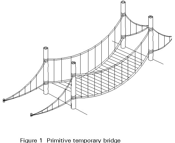
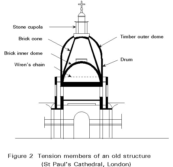
Structural stability depends on a balance between elements sustaining either tensile or compressive stresses. Because natural materials are more suited to resist compression, the traditional objective of the designer has been to avoid tensile stresses using ingenious systems such as arches, vaults, domes, etc. Special treatment of natural materials , however, allowed the development of structures, usually temporary, where the tension members played a fundamental role (Figure 1). Even in situations of fundamentally massive construction tension elements can be found helping to stabilise the system (Figure 2). The Industrial Revolution, during which time ferrous materials were developed, brought great advances in the use of tensile elements as pure tension could now be safely transmitted without the previous durability problems associated with natural materials.
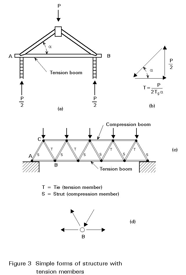
Some simple forms of structures with tension members are given in Figure 3: these are an inclined roof with a tension beam, and a truss whose bottom chord and several diagonals are in tension. More recent developments use cables as tension members in such structures as roofs, bridges, masts, cranes etc. The present lecture deals with conventional tension members; cables are discussed in Lecture 7.4.2.
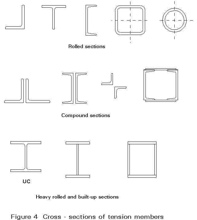
Generally tension members are designed using rolled sections, bars or flats. When more area is needed or connection design requires it, it is possible to combine profiles or to build up a specific section using plates (Figure 4). Flats are generally not used because of their high flexibility; for good practice the slenderness should be limited to 300 for principal members or 400 for secondary members (obviously this rule does not apply to round bars). In general, rolled sections are preferred and the use of compound sections is reserved for larger loads or to resist bending moments in addition to tension.
It is generally assumed that the distribution of stresses in cross-sections of members subjected to axial tensile forces is uniform. However, there are some parameters which result in a non-uniform distribution of stresses; these are:
The influence of these parameters on the behaviour of the cross-section is discussed in Sections 2.2 and 2.3.
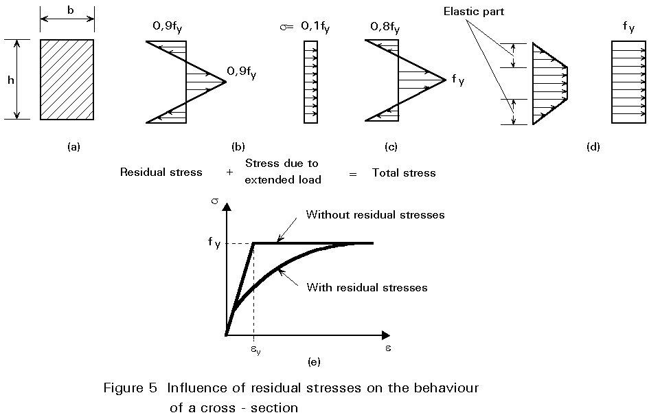
Residual stresses develop when the member is formed and are due to the production process. Their origin can be thermal, either developed during the solidification of the steel or during welding parts of the member; or they can be mechanically induced when trying to produce counter-deflection or when straightening the member. The induced stresses are self equilibrated and although they do not affect the ultimate resistance of the member they induce non-linearities in the strain-stress behaviour as well as greater deformability.
Consider, for example, a rectangular section with residual stresses subjected to an axial force (Figure 5); although the distribution of stresses due to this force is uniform, the corresponding distribution of the total stresses is not. When the combined stresses (Figure 5c) reach the yield strength fy, yielding of the relevant fibres commences and the elastic part of the section is continuously reduced as the external force increases (Figure 5d); the ultimate limit state is reached when the entire section has yielded. Although the behaviour of the section is non-linear (Figure 5e), the ultimate limit state is identical for both cases with and without residual stresses.
Connections are generally made either by bolting or welding.
When several members have to be connected, additional plates must be used which introduce secondary effects due to the moments developed. Sometimes it is possible to reduce these local eccentricities by varying the weld lengths or the bolt distribution.
In addition, the holes that are needed to fix the bolt significantly distort the ideal behaviour of the cross-section.
Firstly, there is an area reduction that has to be taken into account and also a distortion in the stress distribution that induces a non-uniformity in the strain; the effect of the holes is to increase the stresses locally around them (Figure 6). For a plate of infinite width the distribution is given by:
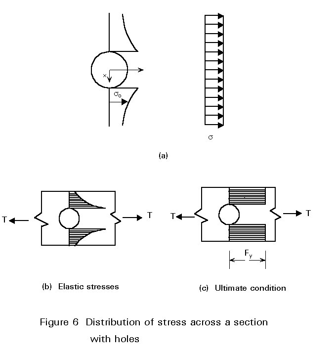
so = s  (1)
(1)
for x ³ R
where R is the hole radius
x is the distance to the point under consideration
when x = R
so = max so = 3s
The above suggests the use of net cross-sections at holes in order to compensate for the weakening effects.
It should be mentioned that, although not reflected in the Codes, the net area might allow for a variety of effects influencing the connection efficiency; these include the ductility of the metal, the care taken when forming the hole (local cracks reduce the ductility), and the relative proportion between hole-diameters and hole distances (inducing a confining effect).
In tension elements the computations are generally related to resistance assessment; however, because of the high slenderness allowed by the optimum use of the material, it is also very important to check their stiffness.
Tension elements are generally subjected to bending induced either by their own weight, dynamic effects like wind or passing loads, or even by unavoidable eccentricities. Good practice rules usually allow for this and a rigorous check is not usually required; as mentioned in Section 2.1 the limits are 300 or 400 for principal or secondary members respectively; some American Codes, however, are more restrictive, see Table 1.
TABLE 1
|
AISC |
AASHTO |
|
|
Main structure Secondary structure Alternating loads |
240 300 - |
200 240 140 |
|
Limit of slenderness l for tension elements l = L/i i2 = I/Awhere: L is the length of the element. i is the minimum radius of gyration. I is the minimum 2nd moment area of the section. A is the area of the cross-section. |
||
The resistance evaluations should check the:
a) Behaviour under static loads, and
b) Behaviour under alternating loads.
This lecture is limited to case a; for tension elements under fatigue conditions reference is made to the Lectures 12.
If the element has no holes, the design axial force resistance is given by:
Npl.Rd = A.fyk / gM1 (2)
where:
A is the gross area of the cross-section.
fyk is the characteristic value of the yield strength.
g
M1 is the partial safety factor for the gross section (gM1 » 1,1).When the member is connected by bolting the section is weakened, suffering a reduction of around 10 to 20% of the gross area. This gives rise to two problems: firstly a reduction in the net area; and secondly, the holes induce stress concentrations that, according to Equation (1) and Figure 6, can reach values three times higher than the uniform distribution. Nevertheless, it is assumed that at the ultimate limit state, due to the ductility of the steel, the stress distribution across the net section is uniform.
The hole diameter should be increased to take account of damaged material when the hole is punched without special precautions; where holes are countersunk the overall diameter should be deducted.
According to Eurocode 3: "the net area of a cross-section or element section shall be taken as its gross area less appropriate deductions for all holes and other openings. Provided that the fastener holes are not staggered the total area to be deducted shall be the maximum sum of the sectional areas of the holes in any cross-section perpendicular to the member axis" [1].
When the holes are staggered it is necessary to use special formulae to calculate the deduction (Figure 7a).
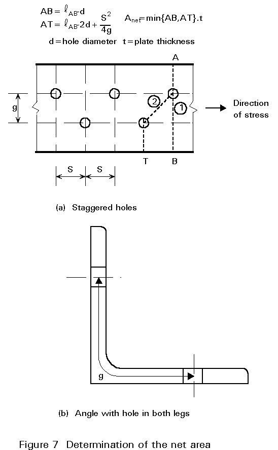
The stress distribution described in Section 2 is more complicated in this case and the Cochrane rule is applied to add the length S2/4g. This is why the Eurocode suggests the following: "When the fastener holes are staggered the total area to be deducted for fastener holes shall be the greater of:
a) the deduction for non-staggered holes.
b) the sum of the sectional areas of all holes in any diagonal or zig-zag line extending progressively across the member or part of the member less S2t/4g for each gauge space in the chain of holes (Figure 7a).
S is the staggered pitch, the spacing of the centres of two consecutive holes in the chain measured parallel to the member axis.
g is the gauge, the spacing of the centres of the same two holes measured perpendicularly to the member axis.
t is the thickness.
In an angle, or other member, with holes in more than one plane, the gauge shall be measured along the centre of thickness of the material (Figure 7b).
In principle, the net area check would be as follows:
NR = Anet.fy / gM2 (3)
where
Anet is the net area
g
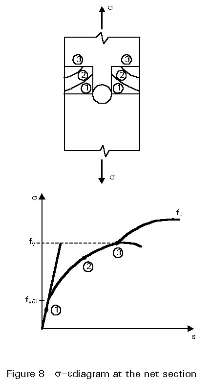
M2 is the partial factor of safety for the net area (gM2 » 1,25)However, the global behaviour of the tension member has to be taken into account. Imagine, for example, that the length affected by the connection is about 5% of the total member length; then assume that the strain at the ultimate load of the connection is 10 times the yield strain (Figure 8).
When the member reaches the yield condition, and the connection the failure condition, the increases in length would be:
Connection zone: ![]()
Member zone: ![]()
That is ![]() » 0,5 (4)
» 0,5 (4)
which means that the elongation within the connection zone is much smaller than that of the entire bar.
This is why Eurocode 3 [1] allows the exceedance of the yield strength in the connection zone up to the ultimate tensile strength, fuk; that is, it is implicitly assumed that the failure of an member can be described by its deformation.
The same philosophy is applied by other codes which, like Eurocode 3, also include a reduction coefficient to take account of the unavoidable eccentricities, stress concentrations, etc. The Eurocode 3 reduction is taken as 10%, so that the recommended formula is:
NnetRd = 0,9Anet.fuk / gM2 (5)
where gM2 is the partial safety factor for resistance with a proposed value of 1,25.
The verification formula is:
NSd £ NRd (6)
where NSd is the design tensile force, and
NRd the design resistance force which is the lesser of the values given by Equations (2) and (5).
If ductile behaviour is desired, it can be seen from Figure 8 that the member has to yield before the connection fails, that is:
Npl.Rd £ Nnet.Rd (7)
or
0,9Anet/A ≥ gM2 fy / gM1 fu (8)
Finally, Eurocode 3 [1] considers the verification for Category C connections; these are slip-resistant connections with preloaded high strength bolts, where slip should not occur at the ultimate limit state.
In this case the failure criteria for the net section is a yield criterion, unlike Equation (5), and so the design resistance is given by:
Nnet.Rd = Anet fy / gM1 (9)
[1] Eurocode 3: " Design of Steel Structures": ENV 1993-1-1: Part 1.1: General rules and rules for buildings, CEN, 1992.