ESDEP WG 11
CONNECTION DESIGN: STATIC LOADING
To introduce connection design, concentrating on the mechanics of load transfer in various forms of connection.
Basic understanding of applied mechanics, and the theories of elasticity and plasticity.
Lecture 2.3: Engineering Properties of Steels
Lecture 2.4: Steel Grades and Qualities
Lecture 11.1.1: Connections in Buildings
Lectures 11.2: Welded Connections
Lectures 11.3: Bolted Connections
Lectures 11.4: Analysis of Connections
Lecture 11.5: Simple Connections for Buildings
Lecture 11.6: Moment Connections for Continuous Framing
Lecture 11.7: Partial Strength Connections for Semi-Continuous Framing
Lecture 11.8: Splices
Lectures 13: Tubular Structures
The principal components of welded and bolted connections are described. The concept of load transfer from the supported member into the supporting member is presented and the different types of load component are identified. The steps involved in tracing the load path, assessing the strength requirements and checking the resistance of components are established in general terms as a prelude to more detailed coverage of the subject in Lectures 11.2, 11.3 and 11.4.
The reasons for connections in all forms of steel construction have already been explained in Lecture 11.1.1. The principal structural and economical requirements were also presented. In this Lecture 11.1.2 the structural requirements (strength, stiffness and deformation capacity) are discussed in greater detail. The Eurocode 3 [1] classification for connections is introduced. This classification considers the stiffness and strength of beam to column connections.
The freedom of the designer to choose the type of connection, and to choose the details for each type, leads to a great variety of connections, see for example the figures in Lecture 11.1.1. The analysis of the structural properties of connections is presented in Section 4, where a number of basic load transfers are identified.
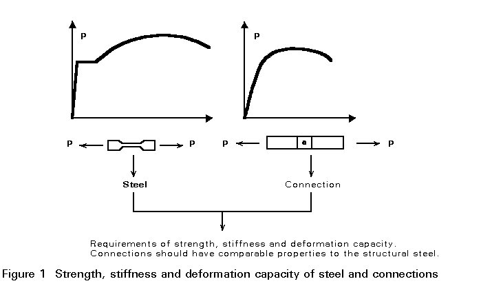
Relevant properties of steel are its strength, its stiffness and its ductility or deformation capacity. These properties can be demonstrated in a tensile test, see Figure 1. A well designed steel structure should possess the same good properties.
The basic requirements for structural elements/connections concern the strength, the stiffness and the deformation capacity.
Figure 2 defines the strength, stiffness and deformation capacity of a beam-to-column connection designed to transfer a moment from the beam into the column.
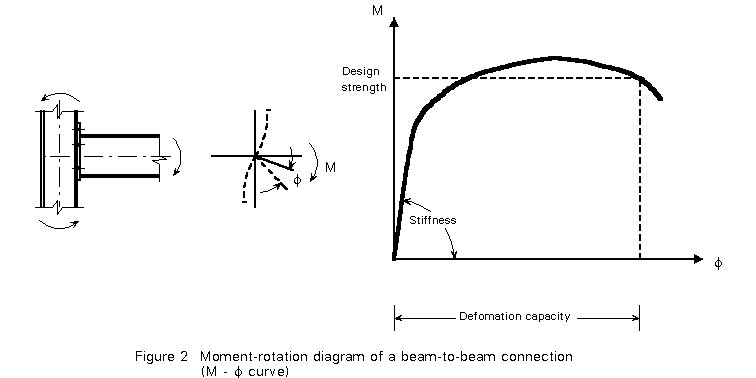
The rotation capacity is a measure of the deformation that can be obtained before failure somewhere in the connection causes a drop in the moment resistance.
The strength, stiffness and deformation capacity of connections are discussed in greater detail below:
Strength
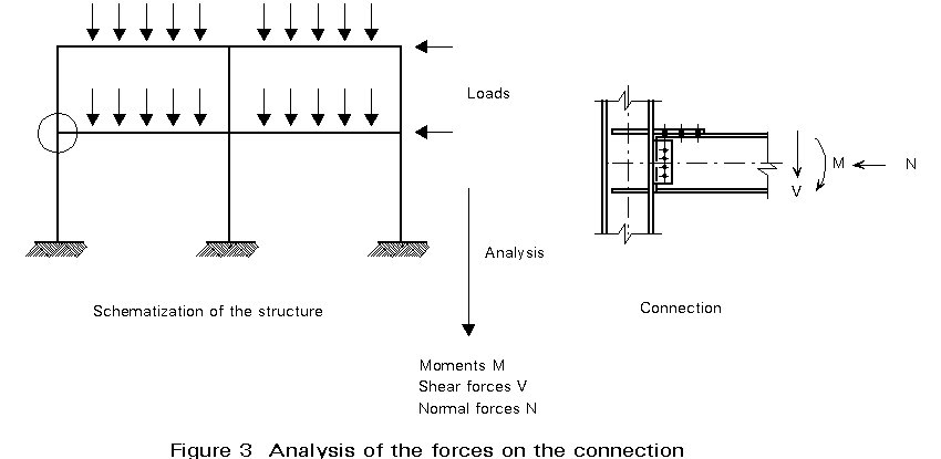
For the determination of the forces on the connection, a static analysis must be carried out. Such analysis includes the determination of the design loads and the modelling of the structure, see Figure 3. In the schematization of the structure, the stiffness of the connections is an important element. Connections can be assumed rigid, as hinges or as having a stiffness between these two. The deformation capacity of the members (beams and columns) and of the connections plays an important role in the ultimate distribution of forces in the structure.
All parts of the structure must be designed so that they can resist the calculated forces and have a deformation capacity that is consistent with the assumptions made in the global analysis.
Stiffness
The stiffness of the connection affects the level of loading for which it should be designed. A connection of low rotational stiffness does not attract major bending moments and therefore may be assumed as a pinned connection in the schematization of the structure.
Of course, the stiffness of the connections affects the deflections of the beams. Especially in non-braced frames the stiffness of the connections may have a major effect on the deflections of the structure as a whole and on its stability.
If the connections are assumed rigid in the modelling for the static analysis of the structure, then consequently the form of the connections should be such that their deformations have a negligible influence on the load distribution and the deformations of the structure.
On the other hand, if pinned connections are assumed, they should have sufficient flexibility to accommodate rotations without causing significant bending moments that may lead to premature failure of (parts of) the connection or connected members.
The schematization of connection stiffness is discussed further in Section 3. In many instances it is acceptable to design connections giving explicit consideration only to their strength.
Deformation Capacity
The requirements for strength and stiffness are clear. They result from the static calculation.
The requirement for deformation capacity is more qualitative. In practice it is sometimes difficult to check this requirement.
Ductile connections that have a great deformation capacity contribute to the overall safety of the structure in the event that the connection becomes overloaded. Such connections may also be a design requirement in certain instances, e.g. when plastic design is employed with plastic hinges forming in the connections.
Connections should be designed according to their required behaviour. Many design approaches are possible for stiffness and strength. In Figure 4 three designs for a beam-to-column connection are given with their moment rotation characteristics.
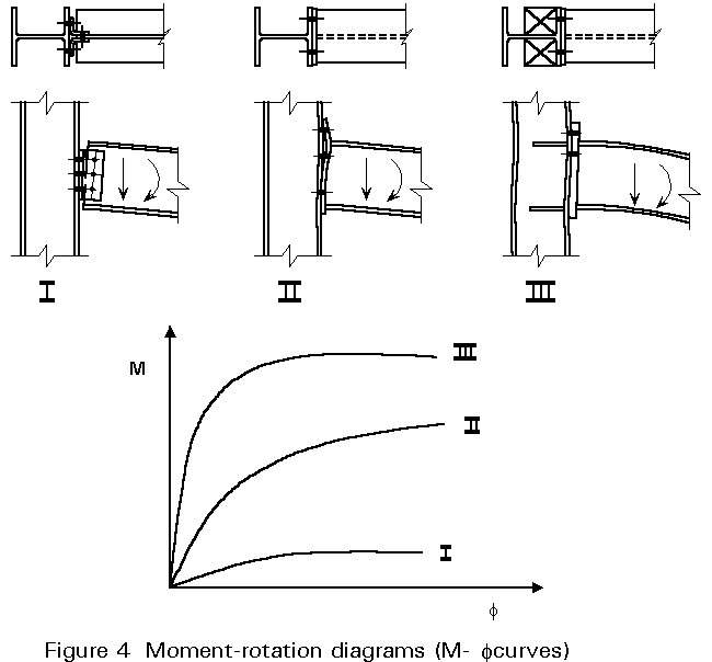
These characteristics may be described as follows:
I Both the rotational stiffness and the moment resistance are small and may reasonably be neglected, leading to the concept of a pinned or hinged connection. Only vertical shear is required to be transferred, with the value being equal to the beam end reaction necessary to resist the beam loading.
II Behaviour intermediate between characteristics I and III, in which the connections possess a finite moment resistance less than the full moment resistance of the beam and a rotational stiffness that permits some relative rotation. (Such connections are usually both semi-rigid and partial strength. However it is possible to have connections that are full-strength and semi-rigid or fully-rigid but only partial strength.)
III The rotational stiffness is very high and the connection's moment resistance is at least that of the beam. Continuity is thus preserved with no rotation of the beam relative to the column; both the beam end reaction and its end moment are transferred to the column.
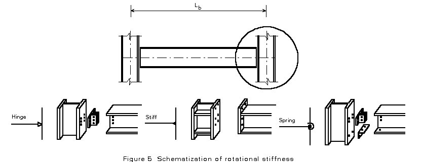
All three possibilities can be applied in multi-storey frames. Type III can be applied in both braced and unbraced frames; Type I is only suitable for braced frames. Type II may be used for both braced and unbraced frames, but in the latter case the influence of connection flexibility on frame behaviour needs to be considered. Figure 5 gives the schematization of rotational stiffness for the frame analysis.
Eurocode 3 [1] provides design rules for both the rotational stiffness and the moment resistance.
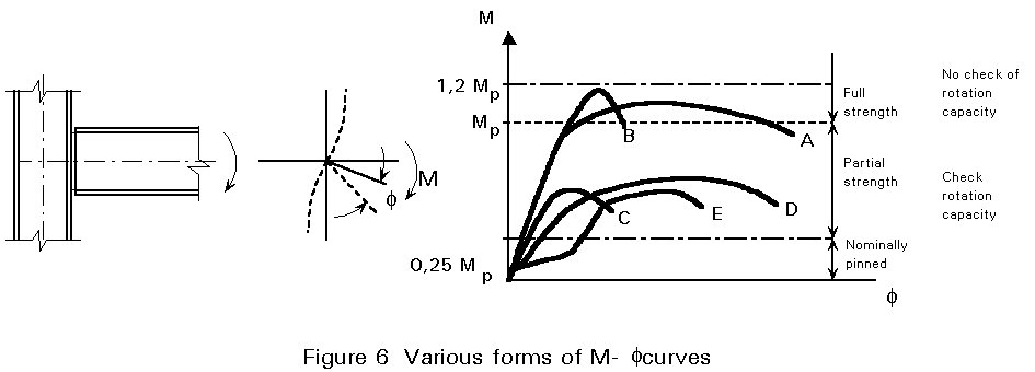
M-f curves as measured in tests are in general non-linear. Another phenomenon is that stiff connections have sometimes a low moment resistance and vice versa. Some examples are shown in Figure 6. M-f curve E is characteristic for some types of bolted connections in clearance holes. At small moments, slip causes a rotation before a higher moment is obtained.
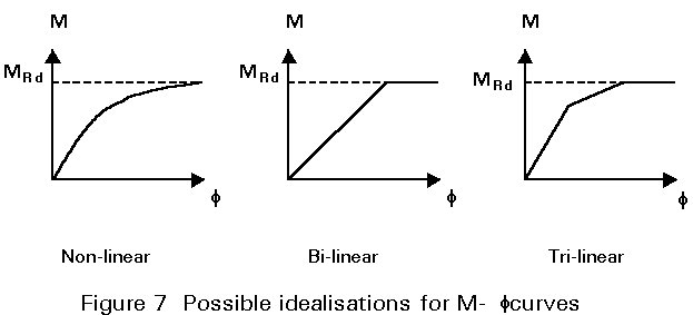
For practical application, it is necessary to idealise the M-f curves. For design a non-linear idealisation or linear idealisations like the bi-linear or tri-linear ones in Figure 7 may be used.
Eurocode 3 [1] gives a classification on the basis of strength and stiffness.
For strength, the following classes can be distinguished:
| nominally pinned | MRd £ 0,25 Mpl.Rd |
| partial-strength | 0,25 Mpl.Rd < MRd < Mpl.Rd |
| full-strength | MRd ³ Mpl.Rd |
| full-strength if rotation capacity is not checked | MRd ³ 1,2 Mpl.Rd |
where
MRd is the design moment resistance of the connection
Mpl.Rd is the design strength of the beam (full plastic moment).
This classification on strength is applicable if the structure is analysed using the theory of plasticity. In a full-strength connection, the plastic hinge is theoretically formed in the beam. In reality however, it is possible that the yield strength of the beam material may be (considerably) higher than its minimum specified value. Therefore it is possible that the plastic hinge will form in the connection despite the calculated MRd > Mpl.Rd. In such cases, it is still necessary that the connection has sufficient rotation capacity to develop the plastic mechanism. Rotation capacity must be proven in all cases. An upper limit is defined, above which it may be assumed that the plastic hinge is always in the beam (1,2 Mpl.Rd).
For stiffness, the classification is as follows:
| nominally pinned | Sj £ 0,5 EIb/Lb |
| semi-rigid | 0,5 EIb/Lb < Sj < 8 EIb/Lb (braced frames) or 25 EIb/Lb (unbraced frames) |
| rigid | Sj ³ 8 EIb/Lb (braced frames) or 25 EIb/Lb (unbraced frames) |
where
Sj is the (secant) rotational stiffness of the connection
EIb is the bending stiffness of the beam
Lb is the span of the beam (see Figure 5).
Design of pinned connections only involves consideration of shear strength and is covered in Lecture 11.5.
For moment connections both shear resistance and moment resistance must be considered. Rigid and/or full strength connections are covered in Lecture 11.6.
Design assuming semi-rigid and/or partial-strength behaviour is explained in Lecture 11.7.
In Section 2 it is indicated that connections should be designed to transfer moments and/or shear forces and/or normal forces, e.g. the connection in Figure 3. The next step in the analysis is to determine the distribution of forces within the connection, Figure 8. It is not necessary and often not feasible to determine the real internal distribution of forces. It is sufficient to assume a realistic distribution, provided that:
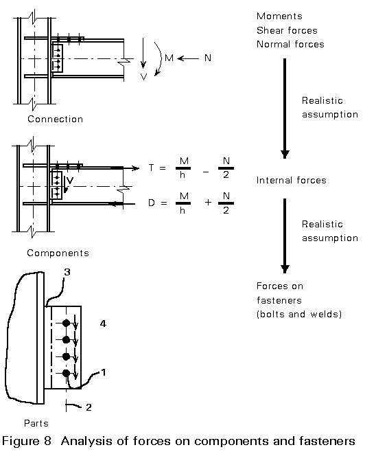
Determining the distribution of forces is the most difficult part of the procedure, because, of necessity, it entails the making of certain simplifying assumptions about the way the connection "works".
In Lectures 11.4 (Analysis of Connections) this subject is covered in detail.
As already indicated in Lecture 11.1.1, a great variety of connection types and connection forms exist.
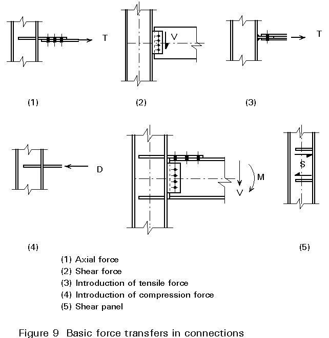
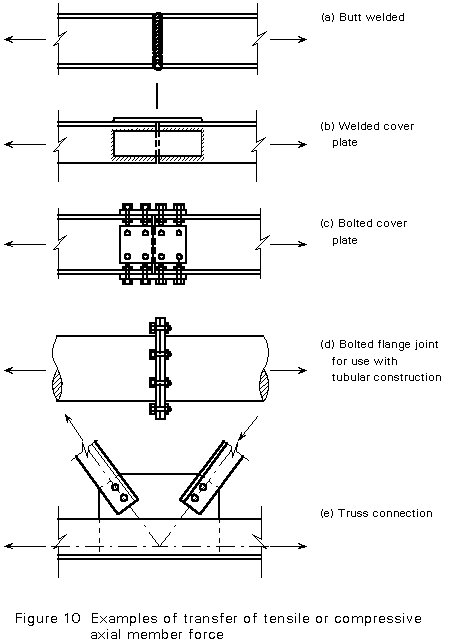
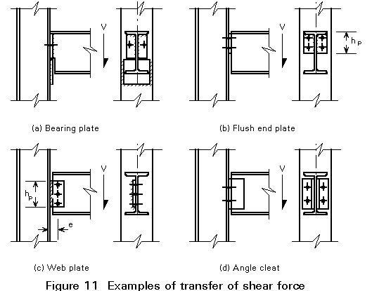
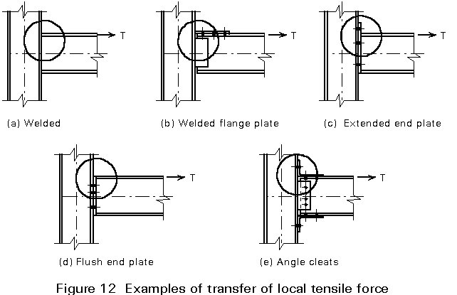
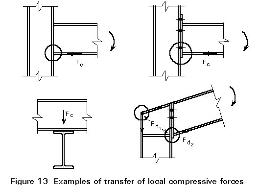
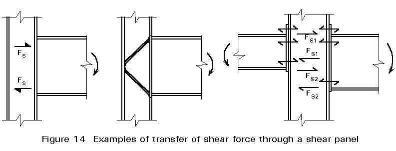
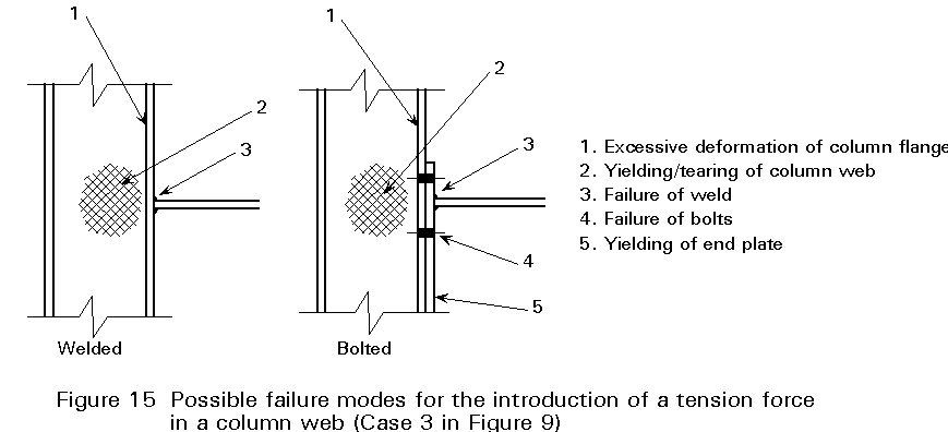
To cover the large variety of types and forms of connections, it is useful to apply the concept of a set of basic force transfers, that can be found in the components of connections. These basic forms are shown in Figure 9. More examples of the basic force transfers are shown in Figures 10 - 14. For each of these basic force transfers a number of failure modes are possible. All of these should be checked. The weakest link determines the resistance of the connection to the applied load. This procedure is illustrated in Figure 15 for the introduction of a tension force in an unreinforced (column) web.
Detailed information on fasteners is given in Lectures 11.2 (Welds) and 11.3 (Bolts), whilst Lectures 11.4 cover the detailed analysis and design of connections using the basic force transfer concept.
[1] Eurocode 3: "Design of steel structures": ENV 1993-1-1: Part 1.1: General rules and rules for buildings, CEN, 1992.
Chapter 6 covers the design of fasteners and of connection components: Annexes J and L deal with the design of beam-to-column connections and column base connections.
Design aid to facilitate the use of Eurocode 3; contains tables and guidelines.
ECCS, Publication No 71, Brussels, 1993
Contains numerous worked examples for the design of bolted and welded connections.
Gives a comprehensive appraisal of bolted joints and reviews in detail methods for design and analysis.
This book presents a wide range of practical solutions for connections in steel and composite buildings. It was translated into four different European languages (French, English, Dutch, Italian).
Thorough treatment of design of multi-storey frame connections. Proposes a range of standardised connections.
Comprehensive text on theory and design of steel structures. Deals extensively with connections.
Explains how flexibility arises in beam to column connections and presents methods for assessing stiffness and strength properties.
Comprehensive coverage of several aspects of connection behaviour and design.
Expands on the more practical aspects of connection design; provides tables to facilitate rigid design in a "look-up" basis.