ESDEP WG 11
CONNECTION DESIGN: STATIC LOADING
To present the basic ideas of the design of connections using ordinary (non-preloaded) bolts.
Lecture 1B.1: Process of Design
Lecture 2.4: Steel Grades and Qualities
Lectures 3.2: Erection
Lecture 11.1.2: Introduction to Connection Design
Lectures 11.3: Other lectures on the Design of Bolted Connections
Lectures 11.4: Analysis of Connections
Lecture 12.6: Fatigue Behaviour of Bolted Connections
This lecture presents the geometrical and mechanical properties of ordinary bolts and describes their behaviour in shear, tension or combined shear and tension.
The effects of the position of the bolts in a connection and of their dimensions on the potential failure modes are also discussed.
A Area of the shank - nominal area [mm2]
As Stress area [mm2]
d Nominal diameter of the bolt (shank) [mm]
do Nominal diameter of the hole [mm]
ds Diameter of the stress area (As) [mm]
e1 End distance [mm]
e2 Edge distance [mm]
F Applied load [N]
Fv Shear force [N]
Fv,Rd Design shear resistance of a bolt [N]
Ft Tensile force [N]
Ft,Rd Design tension resistance of a bolt [N]
Fb.Rd Design bearing resistance [N]
fu Ultimate tensile strength of a steel element [MPa]
fu,b Nominal ultimate stress of the bolt material [MPa]
fy,b Nominal yield stress of the bolt material [MPa]
p1, p2 Pitches [mm]
t Plate thickness [mm]
g
Mb Partial safety factor for the bolt [-]The resistance of a bolted connection is normally determined on the basis of the resistance of the individual fasteners and the connected parts.
Linear-elastic analysis is most frequently used in the design of the connection. Alternatively non-linear analysis of the connection may be employed, provided that it takes account of the load-deformation characteristics of all the components of the connection. Further information about analysis of connections is given in Lectures 11.4.
The present lecture concentrates on the most common type of bolt, the non- preloaded bolt, often called an "ordinary bolt". It is popular because of its low cost both to buy and to install. Connections made with this type of bolt are often referred to as "bearing-type" so as to distinguish them from the slip resistant connections that employ preloaded bolts.
Where a joint loaded in shear is subject to impact or significant vibration, welding or bolts with locking devices, preloaded bolts or other types of bolt which effectively prevent movement should be used.
Where slip is not acceptable in a joint subject to reversal of shear load (or for any other reason), preloaded bolts in a slip-resistant connection, fitted bolts, injection bolts or other bolts with the same effect should be used, see Lectures 11.3.2 and 11.3.3.
For wind and/or stability bracing, bolts in bearing-type connections may normally be used.
In structural connections, bolts are used to transfer loads from one plate to another. The following figures give some examples where bolts are used, loaded by:
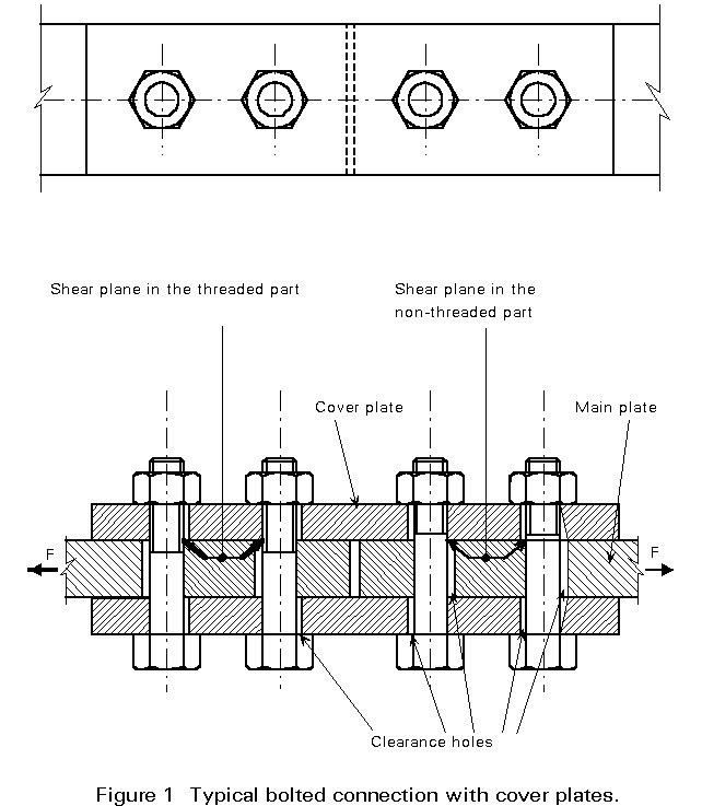
a. Shear force (Figure 1)
The load is transmitted into and out of the bolts by bearing on the connected plates. The forces in the bolts are transmitted by transverse shear.
b. Tension force (Figure 2, only M)
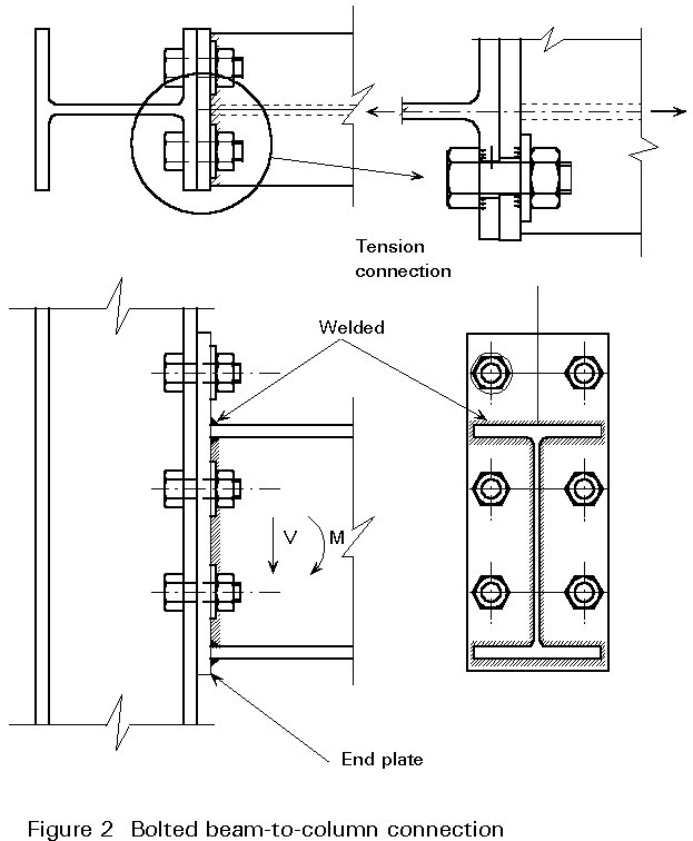
In the case of moment loading (M) only, the tension part of the load is transmitted by axial tension in the bolt.
c. Combined tension and shear force (Figure 2, M and V)
In the case of combined moment (M) and transverse loading (V), the bolts may be required to transmit a combination of transverse shear and axial tension.
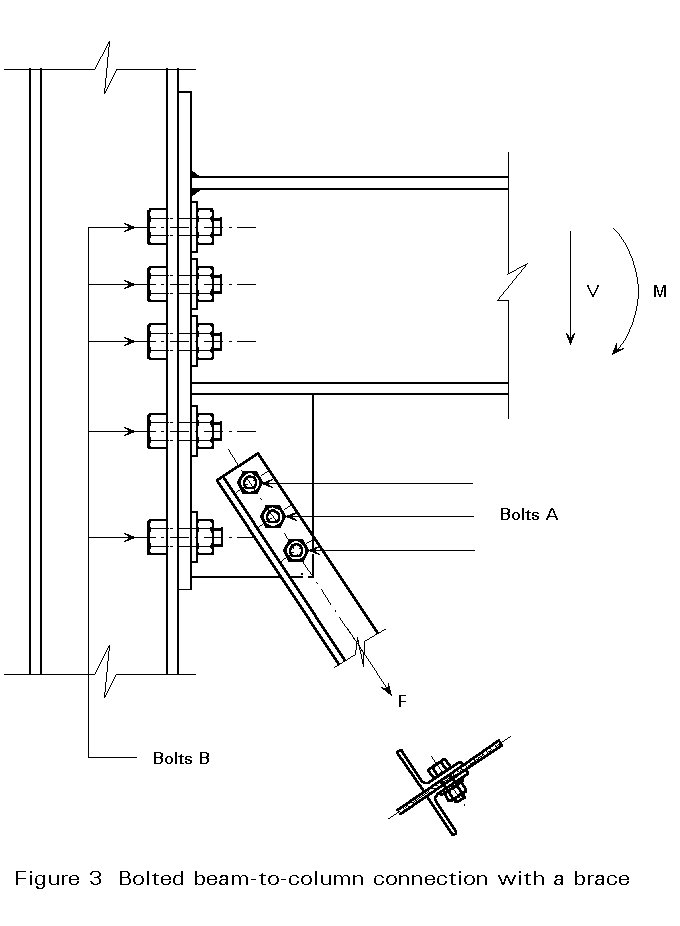
In Figure 3, the bolts A transmit transverse shear, while the bolts B transmit a combination of shear and tension or shear and compression.
Bolts that are not preloaded to a predetermined preload, may be called "non-preloaded bolts" or "ordinary bolts". In case of a shear connection (Figure 1), these bolts are also called "bearing type" bolts.
The principal action on a bolt in a splice joint of the type shown in Figure 4 is shearing on its cross-sectional plane caused by bearing between opposing plates in the joint. The elastic distribution of these bearing stresses and the stresses produced in the bolt are complex. However, for fully developed plastic conditions, the distribution of shear stress is effectively uniform so that the shear strength is the product of the cross-section area of the bolt in the shear plane and the shear strength of the material.
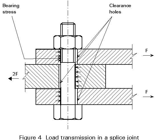
If threads are excluded from the shear plane, the shank area may be used. Otherwise the stress area of the threaded portion should be used. In modern detailing practice it is common to use the smaller area and not to contrive to exclude the threads from the shear plane.
Hexagon headed bolts and nuts are available in a range of sizes up to about 68 mm shank diameter.
The bolt sizes are indicated by the designation M followed by a number multiplied by another number, for example, M 20 x 60, where the diameter of the shank is 20 mm and the length of the shank + the threaded part is 60 mm. The M stands for metric.
The length of the bolt should be such that, after allowing for tolerances, the threaded shank will protrude not less than one thread beyond the nut after tightening and at least one full thread (in addition to the thread run-out) will remain clear between the nut and the unthreaded part of the shank.
Bolts and nuts are available in steels of minimum tensile strengths up to about 1370 MPa.
The grade of the bolts is indicated by two numbers. The most common grades are 4.6, 5.6, 6.5, 6.8, 8.8 and 10.9.
According to Eurocode 3 (2), the design yield stress fyb and the design ultimate stress fub of the usual bolts are as given in Table 1.
Table 1: Mechanical properties of bolts
|
Grade |
4.6 |
5.6 |
6.5 |
6.8 |
8.8 |
10.9 |
|
fyb (MPa) fub (MPa) |
240 400 |
300 500 |
300 600 |
480 600 |
640 800 |
900 1000 |
The design yield stress fyb can be derived from the grade by multiplying the first number by the second number times 10. The design ultimate stress fub is the first number times 100 (stresses in MPa).
Bolts of grade 8.8 are used most frequently.
Because of the tolerances in the positioning of holes and the tolerances of the bolt diameter (d) and the hole diameter (db), a clearance is necessary (Figure 4).
For bearing-type connections, this clearance may cause slip of the plates when they are loaded.
In the case of alternating loading, this movement may occur at each loading reversal. Normally, such movement is not permitted.
Except for fitted bolts or where low-clearance or oversize holes are specified, the nominal clearance in standard holes shall be:
Holes with smaller clearances than standard holes may be specified.
Holes with 2mm nominal clearance may also be specified for M12 and M14 bolts, provided that the design meets the following requirements:
Holes will be formed by drilling or punching. Punching holes in steelwork is much faster than drilling but some cracking may appear in the material and therefore, in some cases, holes will not be punched full size but must be punched 2mm diameter less than full size and then reamed. New punching machines which operate at high speeds induce less distortion in the material, and it is expected that more punching will be allowed in the future.
If there is no specification, punching is allowed for material up to 25mm in thickness provided that the hole diameter is not less than the thickness of the material.
Burrs should be removed from holes before assembly except that, where holes are drilled in one operation through parts clamped together which would not otherwise be separated after drilling, they need to be separated to remove the burrs.
Bolts in structural steelwork must comply with ISO 898/1 (1).
Figure 5 defines the various diameters of such bolts. the area of the shank that is used in design formulae is called the shank area A :
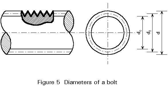
A = pd2/4 (1)
the area of the threaded part that is used in design formulae is called the stress area As:
As = pds2 /4 (2)
The stress diameter ds is somewhat larger than the diameter of the core, because of the fact that a rupture plane always includes at least one thread.
ds is the mean value between the core diameter (dc) and the flank diameter (df) of the thread; the flank diameter is the mean value between the core diameter and the nominal diameter (d):
df = ![]()
ds = ![]()
The value of As for common bolt diameters is given in Table 2.
Table 2: Stress area of bolts
|
Nominal diameter db (mm) |
Nominal area A (mm2) |
Stress area As (mm2) |
|
8 10 12 14 16 18 20 22 24 27 30 |
50,3 78,5 113 154 201 254 314 380 452 573 707 |
36,6 58,0 84,3 115 157 192 245 303 353 459 561 |
Shearing tests on bolts have shown the shear strength to be about 60% of the tensile strength. The effective shear strength of bolts in joints is reduced by secondary bending actions caused by uneven bearing of the plates and by bending of the bolt due to excessive hole clearance. The reduction increases with the length of the bolt for a given diameter. It is particularly significant in lap joints with a single bolt, where the loading tends to straighten out the joint and rotate the bolt as shown in Figure 6, causing both shear and tension in the bolt and local bending stresses under the head and the nut. The reduction in shear resistance of a single fastener may be about 10%. Increasing the length of the joint, i.e. the number of bolts, reduces the bending and hence the loss of shear resistance.
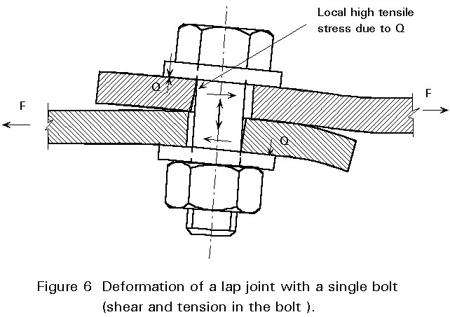
The local bending stresses under the head and the nut in the single bolted connection of Figure 6 may give poor performance in the case of fatigue loading.
The design shear resistance of a bolt (Fv.Rd) in normal conditions, per shear plane, is:
(a) For the shear plane passing through the threaded portion of the bolt:
Fv,Rd = 0,6fubAs/gMb (3)
for strength grades 4.6, 5.6 and 8.8
Fv,Rd = 0,5fubAs/gMb (4)
for strength grades 4.8, 5.8, 6.8 and 10.9
The coefficient 0,5 is the result of a statistical evaluation based on a very large number of test results. It appears that bolts of these grades are less ductile and that the rupture occurs suddenly.
(b) For the shear plane passing through the unthreaded portion of the bolt:
Fv,Rd = 0,6fubA/gMb (5)
The distribution of load between the bolts in a joint when the hole clearance has been taken up depends on the length, the relative cross-sectional areas of the joined plates, the bolt pitch and the shear deformation capacity of the bolts and their immediately surrounding plate (fastener flexibility).
Figure 7 shows the distribution of loads between the bolts in a long joint. The loads transferred through the outer bolts (1 and 9 in the Figure) are greater than those through bolts towards the centre of the joint. If the total area of the cover plates exceeds that of the centre plate the distribution will not be symmetrical, and bolt 1 will transfer more load than any other.
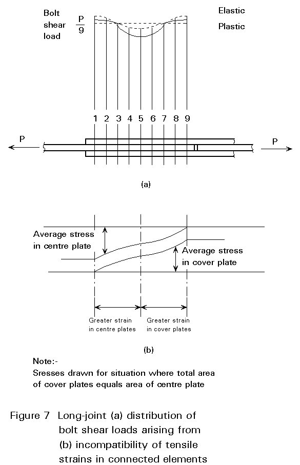
When the fasteners yield, their flexibility increases causing a more uniform sharing of the load (the broken line in Figure 7). However, for long steelwork joints of normal proportions this behaviour will be insufficient to produce an equal load distribution. This the end-bolts will reach their deformation limit and so fail before the remaining ones have been fully loaded. This will result in progressive failure at an average shear value per bolt below the single-bolt shear resistance. Tests have confirmed that joint length, rather than the number of bolts, is the dominant parameter [3].
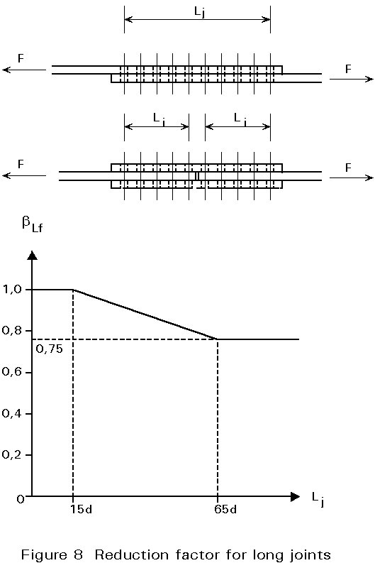
Where the distance Lj between the centres of the end fasteners in a joint, measured in the direction of the transfer of force (see Figure 8), is more than 15d, (where d is the nominal diameter of the bolts) the design shear resistance of all the fasteners shall be reduced by multiplying it by a reduction factor bLf, given by:
bLf = 1 - ![]()
but bLf £ 1,0 and bLf ³ 0,75.
This provision does not apply where there is a uniform distribution of force transfer over the length of the joint, e.g. the transfer of shear force from the web of a section to the flange.
Yielding due to pressure between the bolt shank and plate material may result in excessive deformation of the plate around the bolt hole and possibly some distortion of the bolt.
The area resisting the bearing pressure is assumed to be the product of the plate thickness and the nominal bolt diameter.
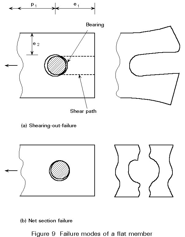
The distance (e1) of the bolt from the end of the plate must be sufficient to provide adequate resistance to the shearing-out mode of failure shown in Figure 9, which is governed by the area of the shear path.
The presence of threads in the grip does not significantly affect the bearing resistance but will cause some increase of the deformation.
If the shear resistance is greater than the bearing resistance of the plates, one of the failure modes shown in Figure 9 will occur. In this case, the deformation capacity of the connection is very large. The joint has a "ductile" behaviour.
In the other case, when the failure is due to the shearing of the bolts, the deformation capacity of the connection is very small and the joint has a "brittle" behaviour.
The design bearing resistance of a bolt [4] is given by:
Fb.Rd = 2,5afudt/gMb (6)
where a is the smallest of:
![]() or 1,0
or 1,0
This reduction coefficient a is necessary, because when the end distance is short, the capacity of deformation is small.
If the net section of the member is small, net section rupture may govern the failure load of the connection (Figure 9).
Equation (6) for the design bearing resistance applies only where the edge distance e2 is not less than 1,5 do and the spacing p2 (Figure 12) measured transverse to the load direction is at least 3,0 do.
If e2 is reduced to 1,2 do and/or p2 is reduced to 2,4 do, then the bearing resistance Fb.Rd should be reduced to 2/3 of the value given by Equation (6). For intermediate values 1,2 do < e2 £ 1,5 do and/or 2,4 do £ 3 do the value of Fb.Rd may be determined by linear interpolation.
Axial tension resistance of a bolt is based on the stress area As and is given by:
Ft = fu,b . As
As a result of statistical evaluation based on a very large number of tests, the following formula should be adopted:
Ft = 0,9 . fu,b . As
The design tension resistance of a bolt is given by:
Ft.Rd = 0,9fubAs/gMb (7)
Generally, when the line of action of the applied force is eccentric to the axis of the bolt, additional tension will be induced in the bolt by prying action.
This action is most easily illustrated in terms of the Tee stub, loaded by a tension force 2F shown in Figure 10. In the bending of the flanges of the Tee, the bolts act as a pivot point so that there is a compressive reaction (Q) between the outer edges of the flanges, which is defined as the Prying Force. The tension induced in the bolts, for equilibrium, is thus Fb = F + Q.
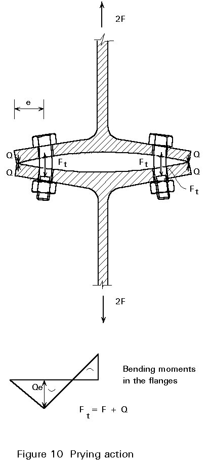
The prying ratio, Q/F, depends upon the geometry and stiffness of the connected parts and the bolt stiffness. An estimate of the prying ratio, taking full account of all the parameters, goes beyond the scope of this lecture. It will be treated in Lecture 11.4.
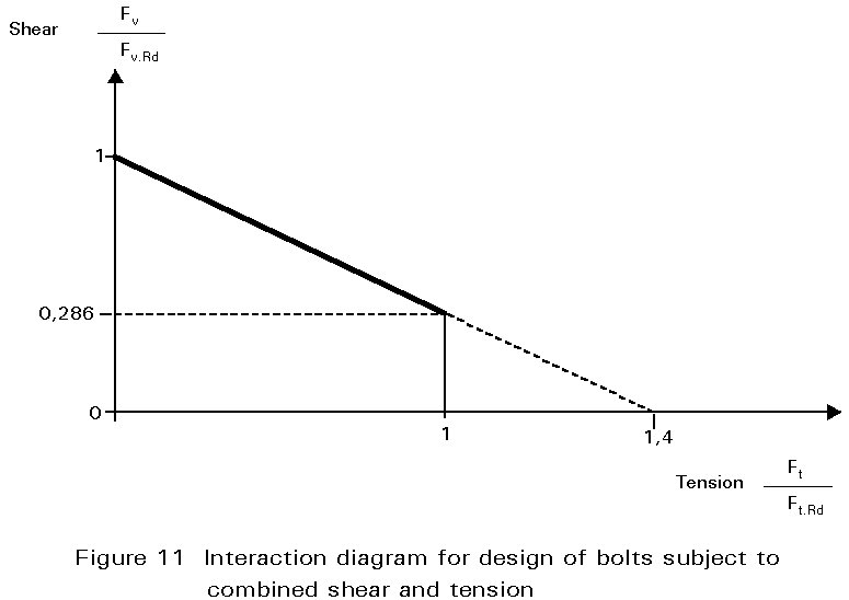
Bolts may be subject to combined shear and tension stresses (Figure 3). Two forces are then acting in the shear plane; Fv (shear) and Ft (tension).
The interaction between the two forces has been investigated in tests [5] and from the results it has been found that bolts subject to shear and tensile force must satisfy the following bi-linear relationship.
![]() £ 1,0
£ 1,0
Thus the full tensile resistance is available for values of shear up to almost 30% of the shear capacity Fv.Rd as shown in Figure 11. This feature is useful when considering situations such as that shown in Figure 2 (M and V) or for bolts B in Figure 3.
The design resistances Fv,Rd and Ft,Rd for shear and tension through the threaded position are restricted to bolts manufactured in conformity with the ISO Standard [1, 6]. For other items with cut threads, such as holding-down bolts or tie rods fabricated from round steel bars where the threads are cut by the steelwork fabricator and not by a specialist bolt manufacturer, the relevant values should be reduced by multiplying them by a factor of 0,85.
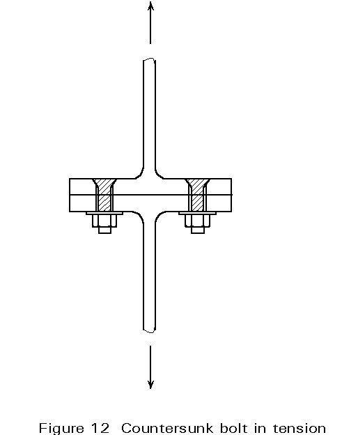
Due to the particular form of the head of a countersunk bolt (see Figure 12) the design tension and bearing resistance of such a bolt have to be reduced.
The positioning of holes for bolts should be such as to prevent corrosion and local buckling and to facilitate the installation of the bolts.
The positioning of the holes shall also be in conformity with the limits of validity for the rules used to determine the design resistances of the bolts with reference to Eurocode 3 (2).
The end distance e1 from the centre of a fastener hole to the adjacent end of any part, measured in the direction of load transfer (see Figure 12a), should not be less than 1,2 do, where do is the hole diameter.
The end distance should be increased if necessary to provide adequate bearing resistance, see Section 8.
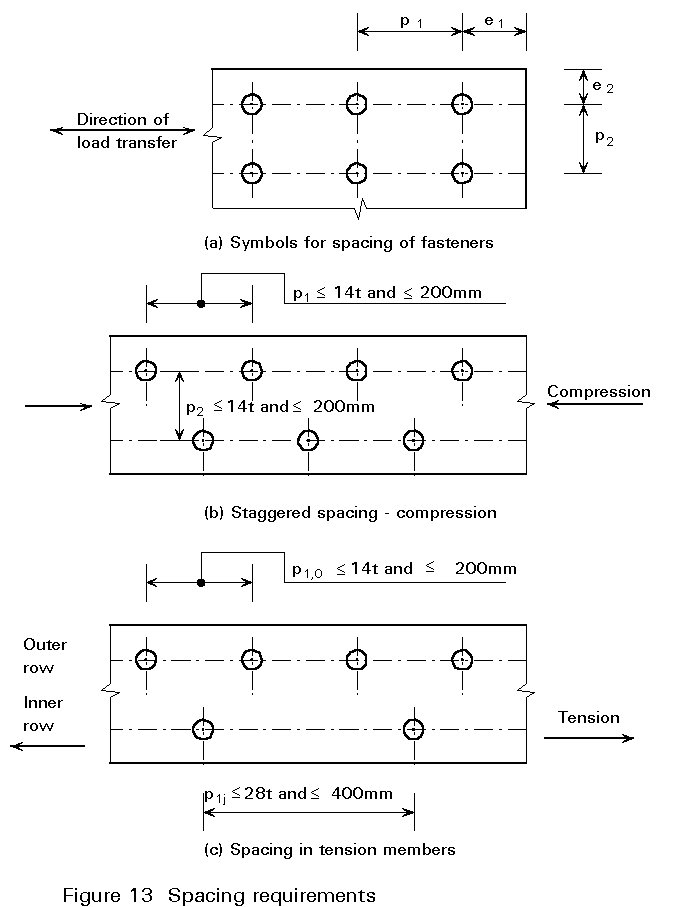
The edge distance e2 from the centre of a fastener hole to the adjacent edge of any part, measured at right angles to the direction of load transfer (see Figure 13a), should normally be not less than 1,5 do.
The edge distance may be reduced to not less than 1,2 do provided that the design bearing resistance is reduced accordingly as given in Section 8.
Where the members are exposed to the weather or other corrosive influences, the maximum end or edge distance should not exceed 40 mm + 4t, where t is the thickness of the thinner outer connected part.
In other cases the end or edge distance should not exceed 12t or 150 mm, whichever is the larger.
The edge distance should also not exceed the maximum to satisfy local buckling requirements for an outstanding element. This requirement does not apply to fasteners interconnecting the components of back-to-back tension members. The end distance is not affected by this requirement.
The spacing p1 between centres of fasteners in the direction of load (see Figure 13b) should not be less than 2,2 do. This spacing should be increased if necessary to provide adequate bearing resistance, see Section 8.
The spacing p2 between rows of fasteners, measured perpendicular to the direction of load, (see Figure 13b), should normally be not less than 3,0 do. This spacing may be reduced to 2,4 do if the design bearing resistance is reduced accordingly, see Section 8.
The spacing p1 of the fasteners in each row and the spacing p2 between rows of fasteners, should not exceed the lesser of 14t or 200 mm. Adjacent rows of fasteners may be symmetrically staggered, see Figure 13b.
The centre-to-centre spacing of fasteners should also not exceed the maximum to satisfy local buckling requirements for an internal element.
In tension members the centre-to-centre spacing p1,i of fasteners in inner rows may be twice that given in Section 10.2.5 for compression in members, provided that the spacing p1,o in the outer row along each edge does not exceed that given in Section 10.2.5, see Figure 13c.
Both of these values may be multiplied by 1,5 in members not exposed to the weather or other corrosive influences.
In the case of unsymmetrical or unsymmetrically connected members such as angles connected by one leg, the eccentricity of fasteners in end connections and the effects of the spacing and edge determine the design resistance.
Angles connected by a single row of bolts in one leg, see Figure 14, may be treated as concentrically loaded and the design ultimate resistance of the net section determined as follows:
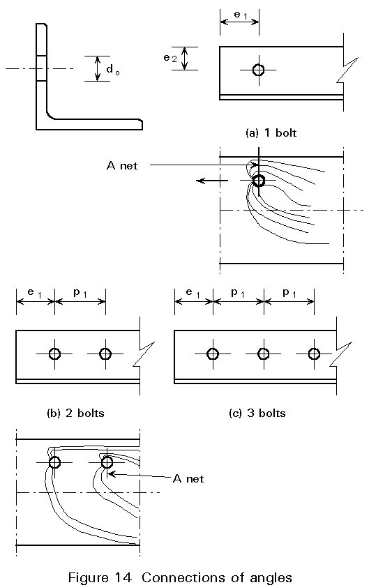
with 1 bolt: Nu,Rd = 2,0(e2 - 0,5do)tfu/gM2
with 2 bolts: Nu,Rd = b3Anetfu/gM2
with 3 or more bolts: Nu,Rd = b3Anetfu/gM2
where b2 and b3 are reduction factors dependant on the pitch p1 as given in Table 3. For intermediate values of p1 the value of b may be determined by linear interpolation,
and Anet is the net section area of the angle. For an unequal-leg angle connected by its smaller leg, Anet should be taken as equal to the net section area of an equivalent equal-leg angle of leg size equal to that of the smaller leg.
Table 3 - reduction factors b2 and b3
|
Pitch p1 |
£ 2,5 do |
³ 5,0 do |
|
2 bolts b2 3 bolts or more b3 |
0,4 0,5 |
0,7 0,7 |
[1] ISO 898/1 - International Standard Mechanical Properties of Fasteners.
Part 1: Bolts, screws and studs.
[2] DD ENV 1993-1-1: 1992, Eurocode 3 "Design of Steel Structures".
Part 1: General Rules and Rules for Buildings.
[3] Kulak, G. L., Fisher, J. W. and Struik, J. H., A Guide to Design Criteria for Bolted and Riveted Joints, 2nd ed, 1987, Wiley.
[4] European Recommendations for Bolted Connections in Structural Steelwork. ECCS publication - Document No. 38.
[5] Shakir-Khalil, H and Ho, C. M., Black Bolts under Combined Tension and Shear, The Structural Engineer, 57B, No 4 (1979).
[6] ISO 898/2 - International Standard Mechanical Properties of Fasteners.
Part 2: Nuts with Specified Proof Load Values.