ESDEP WG 1B
STEEL CONSTRUCTION:
INTRODUCTION TO DESIGN
To introduce the challenge of creative design and to explain approaches by which it may be achieved.
A general knowledge of basic applied mechanics is assumed and prior encouragement should be given to read J E Gordon's three books [1,2,3].
Since this lecture deals with the process of design in general terms almost all other lectures are related to it in some way. Those sections which are most closely associated with it are 1B:Introduction to Design, 14: Structural Systems: Buildings, 15A: Structural Systems: Offshore, 15B: Structural Systems: Bridges, and 15C: Structural Systems: Miscellaneous
The lecture begins by considering a definition of design and some objectives. It discusses how a designer can approach a new problem in general and how a structural designer can develop a structural system. It concludes by considering differences of emphasis in design approach for different classes of structure.
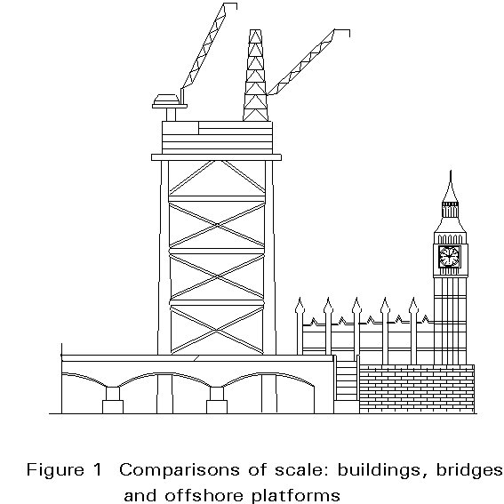
The results of successful design in structural engineering can be seen and used by everyone, see Figure 1.
The question is: how can professional designers be developed and eventually produce better designs than those previously encountered, to benefit and enhance the performance of human activities? In particular how can steel be utilised effectively in structures for:
Design is 'the process of defining the means of manufacturing a product to satisfy a required need': from the first conceptual ideas, through study of human intentions, to the detailed technical and manufacture stages, with the ideas and studies communicated with drawings, words and models.
'Designers'? All people are capable of creative conceptual ideas - they are continuously processing information and making conscious imaginative choices, e.g. of the clothes they wear, of the activities they engage in, and the development of ideas they pursue, causing changes.
In structural design, prime objectives are to ensure the best possible:
These points could possibly be satisfied by either:
Both these extreme approaches are unlikely to be entirely satisfactory. In the former case, the problem may well be slightly different, e.g. the previous bridge may have stimulated more traffic flow than predicted, or vehicle weights may have increased. Economic and material conditions may have changed, e.g. the cost of labour to fabricate small built-up steel elements and joints has increased compared to the production cost of large rolled or continuously welded elements; also, corrosion resistant steels have reduced maintenance costs relative to mild steel. Deficiencies of performance may have been discovered with time, e.g. vibrations may have caused fatigue failures around joints. Energy consumption conditions may have changed, e.g. relating to the global discharge of certain chemicals, the cost of production of certain materials, or the need for greater thermal control of an enclosed space. Finally, too much repetition of a visual solution may have induced boredom and adverse cultural response, e.g. every adjacent building is produced in the "Post Modern Style".
With the latter approach, 'life is often just too short' to achieve the optimal solution whilst the client frets.... Civil and structural engineering projects are usually large and occur infrequently, so a disenchanted client will not make a second invitation. Realisation of new theoretical ideas and innovations invariably takes much time; history shows this repeatedly. Thus methodical analysis of potential risks and errors must temper the pioneering enthusiast's flair.
Positive creative solutions must be achieved for all aspects of every new problem. The solutions will incorporate components from the extremes above, both of fundamental principles and recent developments. However, throughout the Design Process it is prudent to maintain a clear grasp of final objectives and utilise relatively simple technical means and solutions.
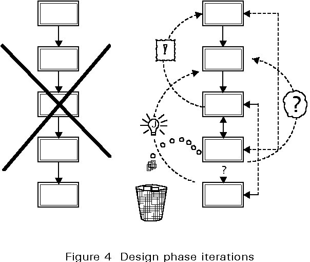
At the outset of a new task an "instant of blind panic" may occur. There are a variety of Design Methods to help progress [4, 5] with the new task, but the following methodical approach is suggested:
At the outset, these five phases appear as a simple linear chain; in fact the design process is highly complex, as all factors in the design are interdependent to a greater or lesser degree. Hence there will be many steps and loops within and between the phases, as seen in Figure 4. The first rapid passage through phases 1, 2 and 3 will decide if there is 'any problem', e.g. is the likely traffic flow adequate to justify a convenient but high cost bridge?
All factors and combinations must be explored comprehensively from idea to detail, with many compromises having to be finely balanced to achieve a feasible solution. Ideas may be developed: verbally, e.g 'brainstorming' or Edward de Bono's 'lateral thinking' approaches [6], graphically, numerically or physically. Always qualitative assessment should proceed quantitative evaluation.
The starting point for Analysis may thus be the designer's current preconceived notion or visual imagination, but the Synthesis will reveal the flexibility of his mind to assimilate new ideas critically, free of preconception.
A designer can prepare himself for the compromises and inversions of thought and interaction with other members of the Design Team leading to successful synthesis, through 'Roleplay Games', e.g. see 'The Monkey House' game, in Appendix 1.
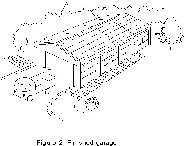
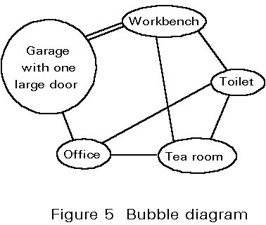
An example of structural design, and the various decision phases, will be briefly considered for a simple two-lorry garage building with an office, toilet and tea room, shown completed in Figure 2. It is assumed in this hypothetical case that an initial decision has already been made by the client to have this set of requirements designed and built.
It is invariably the best idea to start by looking at the functions (performance) required and their relationships. Make a list of individual functions; then generate a 'bubble' (or flow) diagram of relationships between different functional areas to decide possible interconnections and locations, see Figure 5. Find, or assume, suitable plan areas and minimum clear heights of each three-dimensional 'volume of space'. A possible plan layout may then be indicated, noting any particular complications of the site, e.g. plan shape, proximity of old buildings, slope or soil consistency.
Many other plan arrangements will be possible and should be considered quickly at this phase.
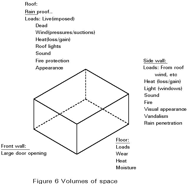
The requirements of each 'volume of space' and its interfaces must be examined for all functional, cost and aesthetic criteria, e.g. what structural applied live loads must be resisted; what heating, ventilating, lighting and acoustic requirements are likely to be desired, see Figure 6.
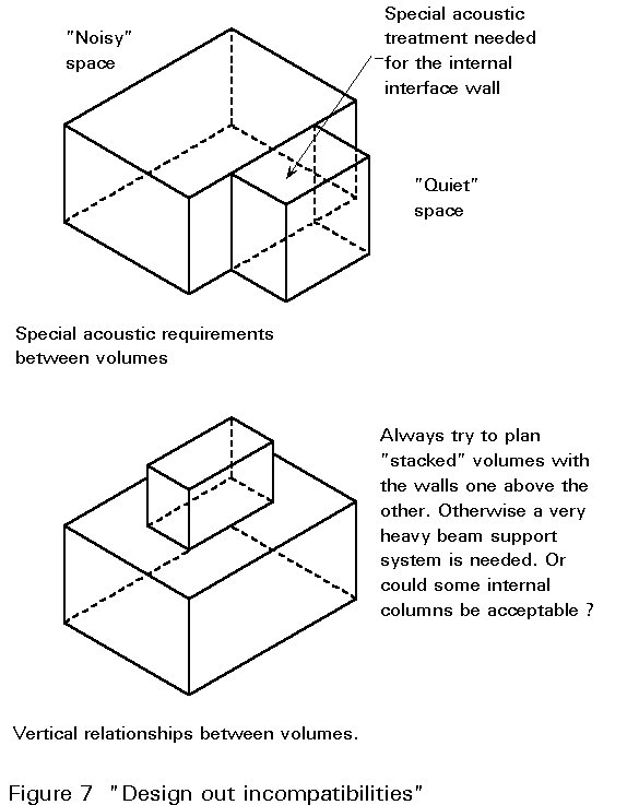
The main criteria can easily be recognised and then followed up and tested by numerical assessment. Incompatibilities may be 'designed out' by re-arranging the planned spaces or making other compromises, see Figure 7, e.g. would you accept an office telephone being very close to the workshop drill or lorry engine, without any acoustic insulation?
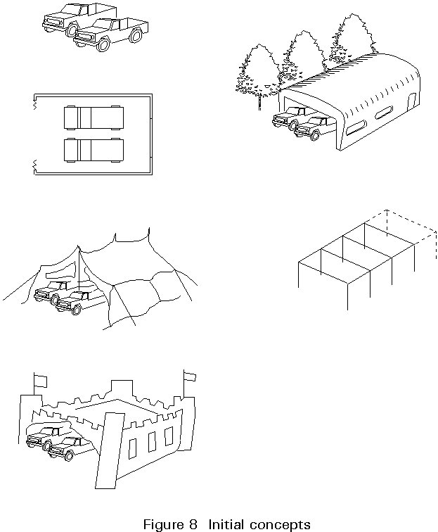
Prepare a set of initial assumptions for possible materials and the structural 'Frame', 'Planar' or 'Membrane' load-bearing system [7] that might be compatible with the 'volumes of space' as shown in Figure 8. These assumptions will be based on previous knowledge and understanding of actual constructions[8-13] or structural theory, see Figure 9 a, b, as well as the current availability of materials and skills. Initial consultations may be needed with suppliers and fabricators, e.g. for large quantities or special qualities of steel.
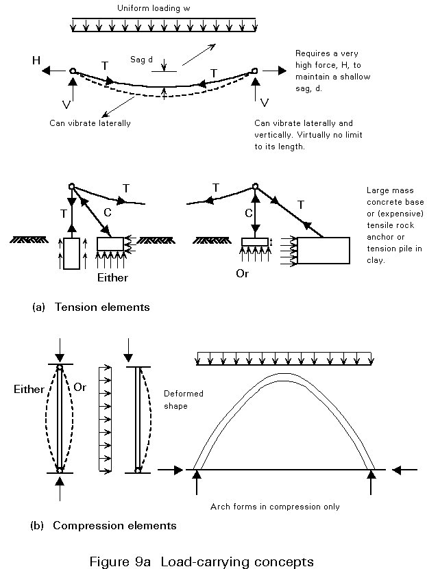
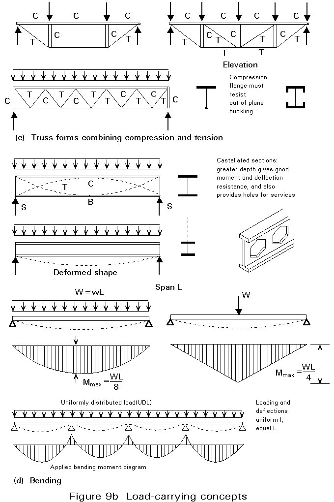
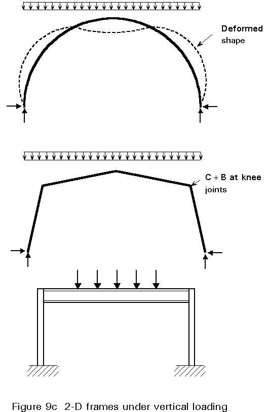
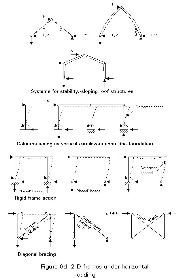
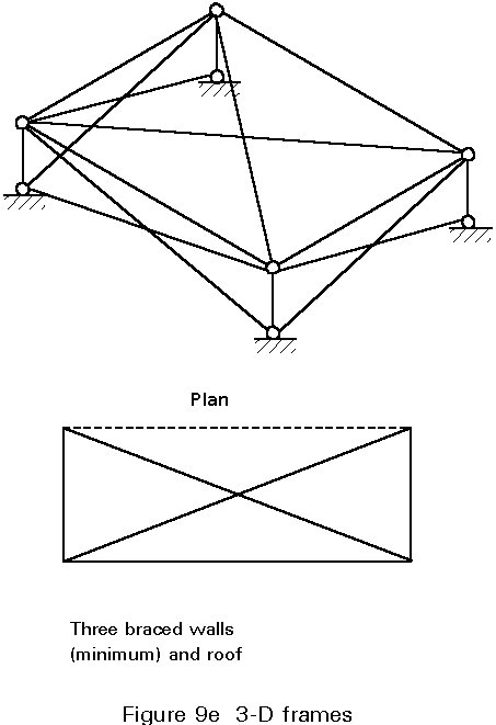
Steelwork, with its properties of strength, isotropy and stiffness, and its straight and compact linear elements, lends itself to 'Frame' systems, see Figure 9 c-e, which gather and transfer the major structural loads as directly as possible to the foundations, as a tree gathers loads from its leaves through branches and main trunk to the roots.
Next (and continuously) elucidate and test your ideas by making quick 3D sketches, or simple physical models, to explore the likely compatibility and aesthetic impact.
A range of stimulating evocative patterns viewed at different distances from, all around, and inside the buildings must be developed:
|
Long range |
the skyline silhouette or "landscape" pattern |
|
Middle distance |
when the whole built object can be seen |
|
Close up |
when a detail is clearly seen |
|
Very close |
when the texture of the materials can be seen. |
All these conditions should be satisfied, and especially for very large buildings for most of the time. Deficiencies may be made up in some people's minds if their social conditions change for the better or natural or changing phenomena occur, e.g. the rays of the setting sun suddenly give a completely different colour appearance or after sunset the interior lighting creates patterns previously unnoticed.
Form, colour, warmth and definition can be achieved with skilful use of steel, especially with "human scale" elements though repetition will soon induce boredom; but only as part of the complete sensory experience which must include elegant solutions to all aspects - especially those easily visible - of the total building design.
It is very important that all principal specialists (architects, engineers for structure and environmental services, and also major suppliers and contractors who should all have common education and understanding of basic design principles) collaborate and communicate freely with each other - also with the client - at this conceptual design phase. Bad initial decisions cannot subsequently be easily and cheaply rectified at the more detailed design phases.
Be prepared to modify the concept readily (use 4B pencils) and work quickly. Timescale for an initial structural design concept: seconds/minutes. But hours will be needed for discussion and communication with others in researching an initial complete design idea.
Consider the applied live loads from roofs, floors or walls, and trace the 'load paths' through the integral 3D array of elements to the foundations, see Figure 10.
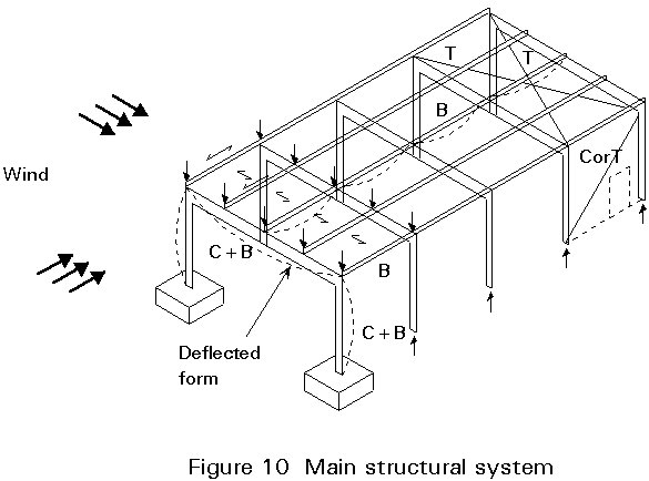
If the roof is assumed to be profiled steel decking, the rainwater should run to the sides, and a manufacturers' data table will indicate both the slope angle to be provided (4° - 6° minimum) and the secondary beam (purlin) spacing required, e.g. commonly 1,4m - 2,6m. The purlins must be supported, e.g. commonly 3m - 8m, by a sloped main beam or truss, usually spanning the shorter direction in plan, and supported by columns stabilised in three dimensions.
Wind loads on the longer side of the building can be resisted by cladding that spans directly to the main columns, or onto sidewall rails spanning between columns. The columns could resist overturning by:
Wind loads on the open short side of the building can be resisted by the opening door spanning top or bottom, or side to side. At the closed short side the wind loads can be resisted by cladding that either spans directly between secondary end wall columns, or onto rails to these columns.
At both ends of the building, longitudinal forces are likely to be induced at the tops of the columns. Trussed bracing can be introduced, usually at both ends of the roof plate, to transfer these loads to the tops of a column bay on the long side - which must then be braced to the ground.
Identify the prime force actions (compression C; tension T; bending B) in the elements and the likely forms of overall and element deflections for all applied loadings both separately and when combined.
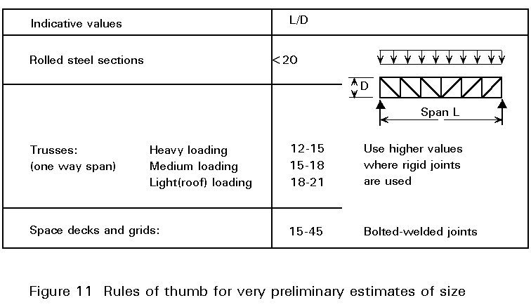
It is always useful to have the elements drawn to an approximate scale, which can be done using manufacturers' data tables for decking and cladding, from observations of existing similar buildings, or using 'Rules of Thumb', e.g. the span/depth ratio for a simply-supported beam equals about 20 for uniform light roof loading, see Figure 11.
At this phase the structural design becomes more definite (use B pencil) and takes longer. Timescale: minutes.
Establish the dead load of the construction and, with the live loads, calculate the following, see Figure 12:
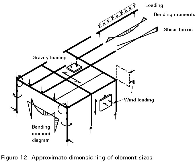
The size of columns carrying little moment can be estimated from Safe Load Tables by using a suitable effective length. Significant bending moments should be allowed for by a suitable increase, i.e. twice or more, in section modulus for the axis of bending.
Beam sizes should be estimated by checking bending strength and stiffness under limiting deflections. Structure/service duct or pipe integration may require beams to be as shallow as possible, or deeper and with holes in the web.
Likely jointing methods must be considered carefully: is the beam to be simply supported or fully continuous and what are the fabrication, erection and cost implications?
Structural calculations are now being performed (use HB pencil with slide rule, simple calculator or computer) and the time involved is more significant. Timescale: minutes/hours.
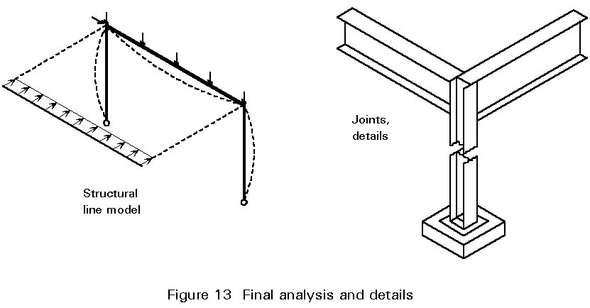
Carry out a full structural analysis of the framework, either elastically or plastically. A computer may well be used, though some established 'hand' techniques will often prove adequate; the former is appropriate when accurate deflections are required, see Figure 13.
For the analysis of statically indeterminate structures, an initial estimate of element stiffnesses (I) and joint rigidity must be determined by the third phase above, before it is possible to find the disposition of bending moments and deflections. If subsequent checking of the design of elements leads to significant changes in element stiffness, the analysis will have to be repeated. The role of the individual element flanges and web in resiting local forces within connections must also be considered very carefully when determining final element sizes. Excessive stiffening to light sections can be prohibitively expensive.
The analysis cannot be completed without careful structural integration and consideration of the compatibility of the entire construction system including its fabrication details.
Element joints will usually be prepared in the factory using welding, with bolts usually completing joints of large untransportable elements at site. Bracings, deckings and claddings will usually be fixed on site with bolts or self-tapping screws. It is important to remember that failures most frequently arise from poor jointing, details and their integration.
The structural calculations and details are now progressing (use HB pencil with slide rule, calculators and computers). Timescale: hours/days.
Iteration of phases 1-4 above will undoubtedly be required, in particular to ensure that the early structural decisions are compatible with the subsequent investigations concerning the functional, environment, cost and aesthetic aspects. The effect of any change must be considered throughout the complete design. Changes usually necessitate a partial 're-design'.
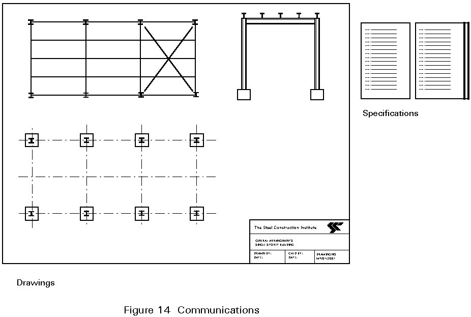
Prepare detail drawings and specifications for contractors' tenders, see Figure 14. Iteration of the design may again be necessary, due to variations in contractors' prices and/or preferred methods, e.g. welding equipment available, difficulties in handling steelwork in the fabricating shop or for transportation and erection. Changes and innovations in the design must be communicated and specified very carefully and explicitly.
In many cases it is common practice for a Consulting Structural Engineer to prepare preliminary designs with choice of main sections, leaving a Steelwork Fabricator to complete the detailed design and jointing system, before checking by the Consultant.
The structural design is now being finalised (use 2 to 4 H pencils and pens, or computers). Timescale: days/weeks.
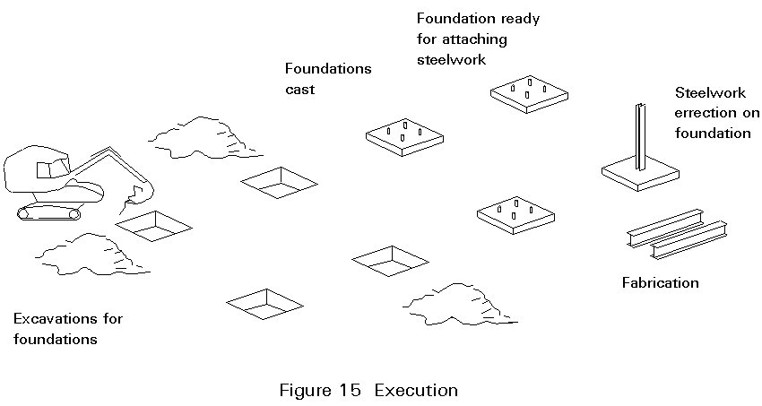
Stability of the structure must be ensured at all stages of the execution, see Figure 15. High quality components and skilled erectors must be available at the right place and time, calling for very careful organisation. If 'all goes to plan' every piece will fit into the complete jigsaw.
The design ideas are now being put into operation (use gumboots). Timescale: weeks/months.
Only regular maintenance already thoroughly planned into the design will be needed, with occasional change and renovation needed with change of use or occupation. Correction of design faults due to innovation and errors should not be needed.
This is the operation phase. (Use a serene outlook on life!) Timescale: years/decades.
Most "traditionally" built timber and masonry houses include some standard steel elements, e.g. hot-rolled steel beams to span larger rooms and support walls, hollow section columns for stair flights, cold-rolled lintels over window openings, stainless steel wall ties and straps, also nails, screws and truss-rafter nail plates.
Cold-rolled galvanised or stainless steel sections can be made up into truss-rafters and replace timber in repetitive conditions. Similar sections can be made up as stud walls, but fire protection of the thin-walled sections will require careful attention, especially for multi-storey houses.
A main steel structural frame may be used for houses, but integration of services, thermal control, fire protection in multi-storeys, corrosion and fabrication costs of elegant jointing must be designed appropriately. Various types of profiled or composite panel cladding can be used for the exterior.
The magnitudes of gravity loading are often relatively greater in bridges, and particular load patterns need to be assessed; also trains of moving wheel loads will occur giving marked dynamic effects. Dynamic effects of wind loading are significant in long-span structures. Accessibility of site, constructability of massive foundations, type of deck structure and regular maintenance cost will govern the system adopted. Aesthetics for users and other observers are important; long distance scale should be appropriately slender but psychologically strong; careful attention is needed for fairly close viewing of abutments and deck underside.
The scale of the whole operation will be very many times that of an onshore building. Gravity loading, wind speeds, wave heights and depth of water are significant design parameters for structure size and stability (here larger elements cause larger wind and wave loads). The scale of the structure also poses special problems for fabrication control, floating out, anchorage at depth by divers and, not least, cost, see Figure 1. Later when the design life is complete, the problems of dismantling should be easy, if considered during the initial design.
[1] Gordon, J. E. 'The New Science of Strong Materials', Pelican.
[2] Gordon, J. E. 'Structures', Pelican.
[3] Gordon, J. E. 'The Science of Structures and Materials', Scientific American Library, 1988.
[4] Jones, J. C. 'Design Methods', Wiley 2nd Edition 1981.
A good overview of general design methods and techniques.
[5] Broadbent, G. H. 'Design in Architecture', Wiley, 1973.
Chapters 2, 13, 19 and 20 useful for designing buildings.
[6] De Bono, E. eg: 'Lateral Thinking' or 'Practical Thinking' or 'The Use of Lateral Thinking', Pelican.
[7] LeGood, J. P, 'Principles of Structural Steelwork for Architectural Students', SCI, 1983 (Amended 1990).
A general introduction and reference booklet to buildings for students.
[8] Francis, A. J, 'Introducing Structures, Pergamon, 1980.
A good overview text, especially Chapter 11 on Structural Design.
[9] Lin, T. Y. and Stotesbury, S. D, 'Structural Concepts and Systems for Architects and Engineers', Wiley, 1981.
Chapters 1-4 give a very simple and thoughtful approach to total overall structural design, especially for tallish buildings.
[10] Schodek, D. L, 'Structures', Prentice Hall, 1980.
Good clear introductory approach to structural understanding of simple concepts, also especially chapter 13 on structural grids and patterns for buildings.
[11] Otto, F, 'Nets in Nature and Technics', Institute of Light Weight Structures, University of Stuttgart, 1975.
Just one of Otto's excellent booklets which observe patterns in nature and make or suggest possible designed forms.
[12] Torroja, E, 'Philosophy of Structures', University of California Press, 1962.
Still a unique source book.
[13] Mainstone, R. J, 'Developments in Structural Form', Allen Lane, 1975.
Excellent scholarly historical work, also chapter 16 on 'Structural Understanding and Design'.
APPENDIX 1
'The Monkey House' roleplay game for a group of students at a seminar, Figure 16
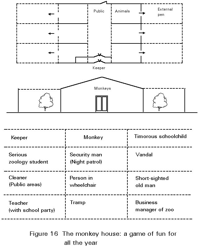
Between 10 and 12 acting roles are created, one for each student in the group, to consider design requirements and interactions. Each actor sees an outline sketch plan of a possible building and has about 3 minutes to prepare his role's requirements, likes and dislikes. These requirements are propounded for about 2/3 minutes to his uninterrupting fellow participants, who note points of agreement/disagreement. When all actors have spoken, the many conflicts are then generally discussed and explored by the actors for about 30 minutes. Then the chairperson seeks a conclusion - who is The Monkey House really for?