ESDEP WG 1B
STEEL CONSTRUCTION:
INTRODUCTION TO DESIGN
To explain the objectives of structural design and the uncertainties which affect it; to outline how different priorities might influence the design, and to describe different approaches to quantifying the design process.
Lecture 1B.1: Process of Design
Lecture 1B.3: Background to Loadings
Lecture 1B.8: Learning from Failures
Lecture 2.4: Steel Grades and Qualities
Lecture 2.5: Selection of Steel Quality
The fundamental objectives of structural design are discussed. The uncertainties associated with designing structures in terms of loading and material properties are considered. The development of structural design methods for strength and resistance is reviewed briefly and the importance of achieving structural stability is explained. Other design considerations such as deflections, vibration, force resistance and fatigue are discussed. Matters of construction and maintenance are included. The importance of considering these aspects and others, such as accommodating services and cladding costs, in developing an efficient design is emphasised. The responsibilities of the designer and the need for effective communication are considered.
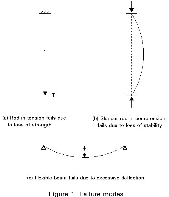
The precise objectives of structural design vary from one project to another. In all cases, the avoidance of collapse is an important - if not the most important - requirement and an adequate factor of safety must be provided. In this context, the structure must be designed in order to fulfil both strength and stability requirements. These concepts are illustrated in Figure 1 in which a long thin rod is subject to tension (Figure 1a) and compression (Figure 1b). In the case of tension, the load resistance of the rod is governed by strength, that is the ability of the material to carry load without rupturing. The rod can only carry this load in compression if it remains stable, i.e. it does not deform significantly in a direction perpendicular to the line of action of the applied load. The stiffness of the structure is yet another important characteristic, concerned with resistance to deformation rather than collapse. This is particulary important in the case of beams whose deflection under a particular load is related to their stiffness (Figure 1c). Large deformations are not necessarily associated with collapse, and some brittle materials, such as glass, may rupture with little prior deformation. Other considerations may also need to be included in the design process. They include: quantifiable behaviour such as deformation, fatigue, fire resistance and dynamic behaviour; considerations such as corrosion and service accommodation which may influence both detail and overall concept, but in a more qualitative way; and appearance, which is largely a subjective judgement. In addition considerations of economy are likely to be a significant influence on the great majority of structural designs. In this context questions of speed and ease of construction, maintenance and running costs, as well as basic building costs, are all relevant. The relative importance of each of these aspects will vary depending on circumstances.
The approach to structural design is dealt with in Lecture 1B.1, which describes how the designer might begin to accommodate so many different requirements, many of which will exert conflicting pressures. In this lecture the focus is on how a satisfactory structural design can be achieved through a rational analysis of various aspects of the structure's performance. It is worth emphasising that the process of structural design can be considered as two groups of highly interrelated stages. The first group is concerned with defining the overall structural form - the type of structure, e.g. rigid frame or load bearing walls, the arrangement of structural elements (typically in terms of a structural grid), and the type of structural elements and material to be used, e.g. steel beams, columns and composite floor slabs. A high degree of creativity is required. The synthesis of a solution is developed on the basis of a broad understanding of a wide range of topics. The topics include structural and material behaviour, as well as a feel for the detailed implications of design decisions made at this stage - for instance recognising how deep a beam may need to be for a particular purpose. Formalised procedures are of little use at this stage. A satisfactory solution depends more on the creative ability of the designer.
The later stages are concerned with the more detailed sizing of structural components and the connections between them. By now the problem has become clearly defined and the process can become more formalised. In the case of steelwork the process generally involves selecting an appropriate standard section size, although in some circumstances the designer may wish to use a non-standard cross-section which, for execution, would then need to be made up, typically by welding plates or standard sections together into plate girders or trusses.
Design regulations are largely concerned with this stage of detailed element design. Their intention is to help ensure that buildings are designed and constructed to be safe and fit for purpose. Such design legislation can vary considerably in approach. It may be based simply on performance specification, giving the designer great flexibility as to how a satisfactory solution is achieved. An early example of this is the building laws published by King Hummarabi of Babylon in about 2200BC. They are preserved as a cuneiform inscription on a clay tablet and include such provisions as 'If a builder builds a house for a man and does not make its construction firm and if the house which he has built collapses and causes the death of the owner of the house, then that builder shall be put to death. If it causes the death of the son of the owner of the house, then a son of the builder shall be put to death. If it causes the death of a slave of the owner of the house, then the builder shall give the owner a slave of equal value'. The danger, and at the same time the attraction, of such an approach is that it depends heavily on the ability of the designer. Formal constraints, based on current wisdom, are not included and the engineer has the freedom to justify the design in any way.
The other extreme is a highly prescriptive set of design rules providing 'recipes' for satisfactory solutions. Since these can incorporate the results of previous experience gained over many years, supplemented by more recent research work they might appear to be more secure. However, such an approach cannot be applied to the conceptual stages of design and there are many cases where actual circumstances faced by the designer differ somewhat from those envisaged in the rules. There is also a psychological danger that such design rules assume an 'absolute' validity and a blind faith in the results of using the rules may be adopted.
Clearly there is a role for both the above approaches. Perhaps the best approach would be achieved by specifying satisfactory performance criteria to minimise the possibility of collapse or any other type of 'failure'. Engineers should then be given the freedom to achieve the criteria in a variety of ways, but also be provided with the benefit of available data to be used if appropriate. Perhaps the most important aspect is the attitude of the engineer which should be based on simple 'common sense' and include a healthy element of scepticism of the design rules themselves.
Simply quantifying the design process, using sophisticated analytical techniques and employing powerful computers does not eliminate the uncertainties associated with structural design, although it may reduce some of them.
These uncertainties include the following:
Loading is discussed in more detail in Lecture 1B.3. Although it is possible to quantify loads on a structure, it is important to recognise that in most cases these represent little more than an estimate of the likely maximum load intensity to which a structure will be exposed. Some loads, such as the self weight of the structure, may appear to be more easily defined than others, such as wind loads or gravity waves on offshore structures. However, there is a significant degree of uncertainty associated with all loads and this should always be recognised.
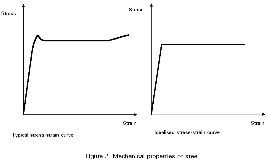
Constitutive laws are typically based on the results of tests carried out on small specimens. For convenience, the mathematical representation of the behaviour, for instance in the form of a stress-strain curve, is considered in a simplified form for the purpose of structural design. In the case of steel the normal representation is linear elastic behaviour up to the yield point with plastic behaviour at higher strains (Figure 2). Although this representation provides a reasonable measure of the performance of the material, it is clearly not absolutely precise. Furthermore, any material will show a natural variability - two different samples taken from the same batch will typically fail at different stresses when tested. Compared with other materials, steel is remarkably consistent in this respect, but nevertheless variations exist and represent a further source of uncertainty.
Methods of analysing structural behaviour have advanced significantly in recent years, particularly as a result of developments in computing. Despite this, structural analysis is always based on some idealisation of the real behaviour. In some cases, such as isolated beams supported on simple bearings, the idealisation may be quite accurate. In other circumstances, however, the difference between the model and the real structure may be quite significant. One example of this is the truss which is typically assumed to have pinned joints, although the joints may in fact be quite rigid and some members may be continuous. The assumption that loadings are applied only at joint positions may be unrealistic. Whilst these simplifications may be adequate in modelling overall performance the implications, at least with regard to secondary effects, must be recognised.
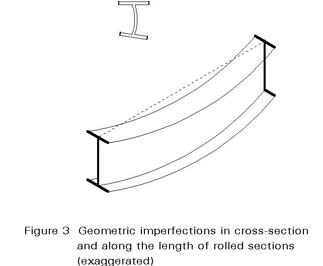
Yet another source of uncertainty results from structural imperfections which are of two types: geometrical, i.e. out of straightness or lack of fit, and mechanical, i.e. residual stresses due to fabrication procedures or inhomogenities in the material properties. It is not possible to manufacture steel sections to absolute dimensions - wear on machinery and inevitable variations in the manufacturing process will lead to small variations which must be recognised. In the same way, although steel construction is carried out to much tighter tolerances than for most other structural materials, some variations (for instance in the alignment of individual members) will occur (Figure 3).
In adopting a quantified approach to structural design, all these uncertainties must be recognised, and taken into account. They are allowed for by the following means:
These measures do not eliminate the uncertainties but simply help to control them within defined bounds.
Structural design is not something which is new. Ever since man started building - dwellings, places of worship, bridges - some design philosophy has been followed, albeit often unconsciously. For many centuries the basis of design was simply to copy previous "designs". Where "new developments" or modifications were introduced, trial and error techniques were all that was available. As a result many structures were built, or partially built only to collapse or perform inadequately. Yet these failures did have a positive value in that they contributed to the fund of knowledge about what is workable and what is not.
This unscientific approach persisted for many centuries. Indeed it still forms part of the design approach adopted today. Rules of thumb and empirical design recommendations are frequently used, and these are largely based on previous experience. Nor is structural engineering today totally free of failures, despite the apparent sophistication of design methods and the power of computers. The dramatic box girder bridge collapses in the early 1970s were a grim reminder of what can happen if new developments are too far ahead of existing experience.
The emergence of new materials, notably cast and wrought iron, required a new approach and the development of more scientific methods. The new approach included testing, both of samples of the material and proof testing of structural components and assemblies. New concepts too were sometimes justified in this way, for instance in the case of the Forth Rail Bridge.
The first moves to rationalise structural design in a quantitative way came at the beginning of the 19th century with the development of elastic analysis. This type of analysis allowed engineers to determine the effect (on individual structural components) of forces applied to a complete structure.
Testing of materials provided information concerning strength and, in the case of iron and steel, other characteristics such as the elastic limit. Of course there were often great variations in the values measured, as indeed there are even today with some materials. In order to ensure a safe design, a lower bound on the test results - a value below which experimental data did not fall - was normally adopted as the 'strength'. Recognising some of the uncertainties associated with design methods based on calculation, stresses under maximum working load conditions were limited to a value equal to the elastic limit divided by a factor of safety. This factor of safety was specified in an apparently arbitrary fashion with values of 4 or 5 being quite typical.
This approach provided the basis of almost all structural design calculations until quite recently, and for some applications is still used today. As understanding of material behaviour has increased and safety factors have become more rationalised, so design strengths have changed. Changes in construction practice, and the development of new, higher strength materials, have necessitated detailed changes in design rules, particularly with regard to buckling behaviour. However the basic approach remained unchanged until quite recently when certain limitations in classical allowable-stress design became apparent. The limitations can be summarised as follows:
i. there is no recognition of the different levels of uncertainty associated with different types of load.
ii. different types of structure may have significantly different factors of safety in terms of collapse, and these differences do not appear in any quantifiable form.
iii. there is no recognition of the ductility and post-yield reserve of strength characteristic of structural steelwork.
The last of these limitations was overcome by the work of Baker [1] and his colleagues in the 1930s when plastic design was developed. This method was based upon ensuring a global factor of safety against collapse, allowing localised 'failure' with a redistribution of bending stresses. A comparison of elastic and plastic design is given by Beal [2].
In recognition of the disadvantages of the allowable stress design method, an alternative approach, known as limit state design has been adopted. Limit state design procedures have now become well established for most structural types and materials. The approach recognises the inevitable variability and uncertainty in quantifying structural performance, including the uncertainties of material characteristics and loading levels. Ideally, each uncertainty is typically treated in a similar manner using statistical techniques to identify typical or characteristic values and the degree of variation to be expected from this norm [3]. It is then possible to derive partial safety factors, one for each aspect of design uncertainty, which are consistent. Thus different load types, for instance, have different factors applied to them. The structure is then examined for a variety of limit states. In that case the structure is designed to fail under factored loading conditions, giving a clearer picture of the margins of safety than was previously the case with allowable stress design.
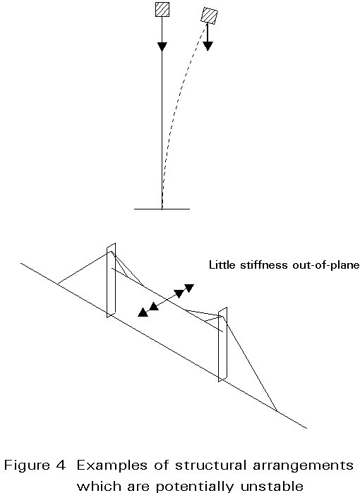
Inadequate strength is not the only cause of collapse. In particular the designer must ensure adequate stability, both of the complete structure (a function of the overall structural form) and of each part of it (dependent on individual member proportions and materials). The latter is generally dealt with by modifying the material strength to account for individual conditions. Overall stability is very much more difficult to quantify and must be carefully considered at the earliest stage of structural design. In this sense structural stability can be defined by the conditions that a structure will neither collapse (completely or partially) due to minor changes, for instance in its form, condition or normal loading, nor be unduly sensitive to accidental actions. Some examples are shown in Figure 4.
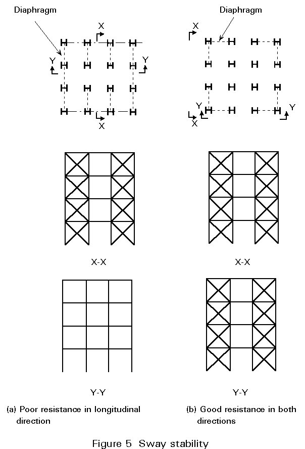
In designing for stability the positioning of the main load-bearing elements should provide a clearly defined path for transmitting loads, including wind and seismic actions to the foundations. In considering wind loads on buildings it is important to provide bracing in two orthogonal vertical planes, distributed in such a way as to avoid undue torsional effects, and to recognise the role of the floor structure in transmitting wind loads to these braced areas (Figure 5). The bracing can be provided in a variety of ways, for instance by cross-bracing elements or rigid frame action.
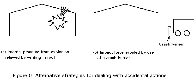
Consideration of accidental actions, such as explosions or impact, is more difficult, but the principle is to limit the extent of any damage caused. Limitation of damage can be achieved by designing for very high loads (not generally appropriate) or providing multiple load paths. Design requires consideration of local damage rendering individual elements of the structure ineffective, and ensuring the remaining structure is able to carry the new distribution of loads, albeit at a lower factor of safety. Alternative strategies are to provide for dissipation of accidental actions, for instance by venting explosions, and to protect the structure, for instance by installing bollards to prevent vehicle impact on columns (Figure 6).
Structural stability must of course be ensured when alterations are to be carried out to existing structures. In all cases stability during execution must be very carefully considered.
In many ways robustness is associated with stability. Construction forms which fulfil the primary function of accommodating normal loading conditions - which are highly idealised for design purposes - may not perform a secondary function when the structure is subject to real loading conditions. For instance the floor of a building is normally expected to transmit wind loads in the horizontal plane to the braced positions. Transmission of wind loads can only be achieved if there is adequate connection between the floor and other parts of the structure and building fabric, and the floor itself is of a suitable form of construction.
Although design against collapse is a principal consideration for the structural engineer, there are many other aspects of performance which must be considered. None of these aspects can be quantified and only certain ones will normally apply. However, for a successful solution, the designer must decide which considerations can be ignored, what the most important criteria are in developing the design, and which can be checked simply to ensure satisfactory performance.
The deflection characteristics of a structure are concerned with stiffness rather than strength. Excessive deflections may cause a number of undesirable effects. They include damage to finishes, (particularly where brittle materials such as glass or plaster are used), ponding of water on flat roofs (which can lead to leaks and even collapse in extreme cases), visual alarm to users and, in extreme cases, changes in the structural behaviour which are sufficient to cause collapse. Perhaps the most common example of deflection effects occurs in columns, which are designed for largely compressive loads but may become subject to significant bending effects when the column deforms in a horizontal plane - the so called P-delta effect.
The normal approach in design is to check that calculated deflections do not exceed allowable levels, which are dependent upon structural type and finishes used. For instance, deflection limits for roof structures are not normally as severe as those for floor structures. In performing these checks it is important to recognise that the total deflection dmax consists of various components, as shown in Figure 7, namely:
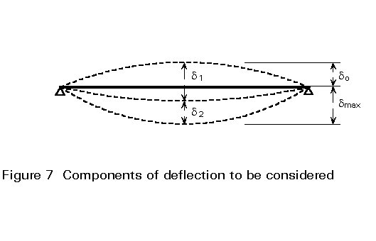
dmax = d1 + d2 - d0
where d1 is the deflection due to permanent loads
d2 is the deflection due to variable loads
d0 is the precamber (if any) of the beam in the unloaded state.
In controlling deflections it is often necessary to consider both dmax and d2, with more severe limits applying in the latter case.
Although the calculated deflections do not necessarily provide an accurate prediction of likely values, they do give a measure of the stiffness of the structure. They are therefore a reasonable guide to structural performance in this respect. With the trend towards longer spans and higher strength materials, design for deflection has become more important in recent years. In many cases this consideration dictates the size of structural elements rather than their resistance. In the case of certain structures, deflection control is of paramount importance. Examples include structures supporting overhead cranes and those housing sensitive equipment. Design for deflection is likely to be the critical condition in such cases.
The vibration characteristics of a structure are, like deflection behaviour, dependent upon stiffness rather than strength. The design principle is to adopt a solution for which the natural frequency of vibration is sufficiently different from any source of excitation, such as machines, to avoid resonance. Longer spans, lighter structures and a reduction in the mass and stiffness of partitions and cladding have all contributed to a general lowering of the natural frequencies for building structures. Cases of human discomfort have been recorded and Eurocode 3 [4] now requires a minimum natural frequency of 3 cycles per second for floors in normal use and 5 cycles per second for dance floors.
Wind excited oscillations may also need to be considered for unusually flexible structures such as very slender, tall buildings, long-span bridges, large roofs, and unusually flexible elements such as light tie rods. These flexible structures should be investigated under dynamic wind loads for vibrations both in-plane and normal to the wind direction, and be examined for gust and vortex induced vibrations. The dynamic characteristics of the structure may be the principal design criterion in such cases.
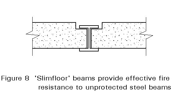
The provision for safety in the event of fire is dealt with in Group 4B. It is a common requirement that structural integrity is maintained for a specified period to allow building occupants to escape and fire-fighting to be carried out without the danger of structural collapse. For steel structures alternative design strategies can be adopted to achieve this requirement. The traditional approach has been to complete the structural design 'cold' and to provide some form of insulation to the steelwork. This approach can give an expensive solution and alternative methods have now been developed, allowing reductions, and in some cases complete elimination, of fire protection. In order to implement these alternatives in an effective manner, it is important that, at an early stage in the design process, the structural design considers how the fire resistance of the steelwork is to be achieved. Adopting a design solution which may be relatively inefficient in terms of the weight of steel for normal conditions may be more than offset by savings in fire protection (Figure 8).
Buildings close to a site boundary may require special consideration to prevent an outbreak of fire spreading to adjacent sites due to structural collapse. Again quantitative design procedures have been developed for such circumstances [5].
Where structures, or individual structural elements, are subject to significant fluctuations in stress, fatigue failure can occur after a number of loading cycles at stress levels well below the normal static resistance. The principal factors affecting fatigue behaviour are the range of stresses experienced, the number of cycles of loading and the environment. Structures which need particular consideration in this respect are crane gantry girders, road and rail bridges, and structures subject to repeated cycles from vibrating machinery or wind-induced oscillations. Design guidance is included in Eurocode 3 [4].
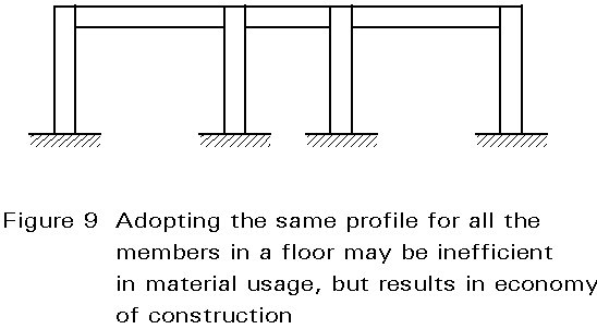
One of the principal advantages of steelwork is the speed with which execution can proceed. In order to maximise this advantage it may be necessary to adopt a structurally less efficient solution, for instance by using the same profile for all members in a floor construction, even though some floor beams are less highly loaded than others (Figure 9). Temporary propping should be avoided as must late changes in detail which might affect fabrication.
It is important that the structure is not considered in isolation, but rather treated as one part of the complete construction, along with services, cladding and finishes. By adopting a co-ordinated approach to the design, integrating the parts and eliminating or reducing wet trades, speed of execution of the project as a whole can be maximised. A good example of this is the two-way continuous grillage system used for the BMW Headquarters at Bracknell and other projects [6].
The installation of services can have significant implications for speed, cost and detail of construction. In buildings with major service requirements, the cost of the services can be considerably greater than the cost of the structure. In such circumstances it may well be better to sacrifice structural efficiency for ease of accommodating the services. The design of the total floor zone including finishes, structure, fire protection and services also has implications for other aspects of the building construction. The greater the depth of floor construction, the greater the overall height of the building and hence the quantity of external cladding required. In many commercial developments very sophisticated and expensive cladding systems are used. Savings in cladding systems may more than offset the use of shallower, but less efficient, floor construction. Where there is strict planning control of overall building height, it may even be possible to accommodate additional storeys in this way.
All structures should be inspected and maintained on a regular basis, although some conditions are likely to be more demanding in this respect. For instance, steelwork within a dry, heated interior environment should not suffer from corrosion, whilst a bridge structure in a coastal area will need rigorous maintenance schedules. Some structural forms are easier to maintain than others, and where exposure conditions are severe, ease of inspection and maintenance should be an important criterion. Principal objectives in this context are the avoidance of inaccessible parts, dirt and moisture traps, and the use of rolled or tubular individual sections in preference to truss-like assemblies composed of smaller sections.
One engineer should be responsible for ensuring that the design and details of all components are compatible and comply with the overall design requirements. This responsibility is most important when different designers or organisations are responsible for individual parts of the structure, such as foundations, superstructure and cladding. It should include an appraisal of the working drawings and other documents to establish, inter alia, that requirements for stability have been incorporated in all elements, and that they can be met during the execution stage.
Effective communication both within the design team and between the designer and constructor before and during execution is essential. Good communication will help to avoid potential design conflicts, for instance when services have to penetrate the structure, and also to promote safe completion of the structure in accordance with the drawings and specification. The constructor may also require information concerning results of site surveys and soil investigations, design loadings, load resistance of members, limits on positions of construction joints, and lifting positions on members to be erected as single pieces. A statement accompanied by sketches detailing any special requirements should be prepared when necessary, e.g. for any unusual design or for any particularly sensitive aspects of the structure or construction. This statement should be made available to the contractor for appropriate action regarding temporary works and execution procedures.
The designer should be made aware of the proposed construction methods, erection procedures, use of plant, and temporary works. The execution programme and sequence of erection should be agreed between the designer and constructor.
Full and effective communication between all parties involved will help not only to promote safe and efficient execution but may also improve design concepts and details. Design should not be seen as an end in itself, but rather as an important part of any construction project.
[1] Baker, J.F., and Heyman, J. "Plastic Design of Frames 1: Fundamentals", Cambridge University Press, 1969.
[2] Beal, A.N. "What's wrong with load factor design?", Proc. ICE, Vol. 66, 1979.
[3] Armer, G.S.T., and Mayne, J.R. "Modern Structural Design Codes - The case for a more rational format", CIB Journal Building Research and Practice, Vol. 14, No. 4, pp. 212-217, 1986.
[4] Eurocode 3 "Design of Steel Structures" ENV1992-1-1: Part 1: General Rules and Rules for Buildings, CEN, 1992.
[5] Newman, G.J. "The behaviour of portal frames in boundary conditions", Steel Construction Institute.
[6] Brett, P.R. 'An alternative approach to industrial building", The Structural Engineer, Nov. 1982.