ESDEP WG 1B
STEEL CONSTRUCTION:
INTRODUCTION TO DESIGN
To explain the philosophy of limit state design in the context of Eurocode 3: Design of Steel Structures. To provide information on partial safety factors for loads and resistance and to consider how the particular values can be justified.
Lecture 1B.1: Process of Design
Lecture 1B.3: Background to Loadings
Lecture 1B.8: Learning from Failures
Lecture 2.4: Steel Grades and Qualities
Lecture 2.5: Selection of Steel Quality
The need for structural idealisations is explained in the context of developing quantitative analysis and design procedures. Alternative ways of introducing safety margins are discussed and the role of design regulations is introduced. The philosophy of limit state design is explained and appropriate values for partial safety factors for loads and strength are discussed. A glossary of terms is included.
The fundamental objectives of structural design are to provide a structure which is safe and serviceable to use, economical to build and maintain, and which satisfactorily performs its intended function. All design rules, whatever the philosophy, aim to assist the designer to fulfil these basic requirements. Early design was highly empirical. It was initially based largely upon previous experience, and inevitably involved a considerable number of failures. Physical testing approaches were subsequently developed as a means of proving innovative designs. The first approaches to design based upon calculation methods used elastic theory. They have been used almost exclusively as the basis for quantitative structural design until quite recently. Limit state design is now superseding the previous elastic permissible stress approaches and forms the basis for Eurocode 3 [1] which is concerned with the design of steel structures. In the following sections the principles of limit state design are explained and their implementation within design codes, in particular Eurocode 3, is described.
The procedures of limit state design encourage the engineer to examine conditions which may be considered as failure - referred to as limit states. These conditions are classified into ultimate and serviceability limit states. Within each of these classifications, various aspects of the behaviour of the steel structure may need to be checked.
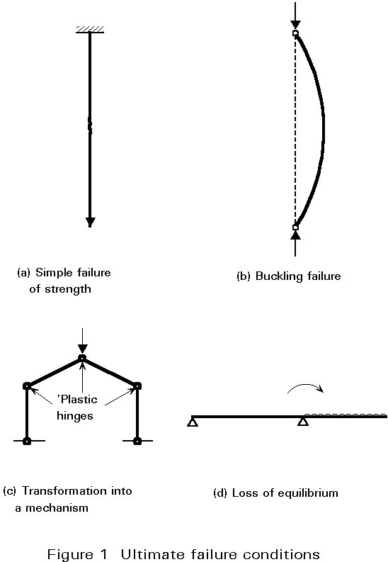
Ultimate limit states concern safety, such as load-carrying resistance and equilibrium, when the structure reaches the point where it is substantially unsafe for its intended purpose. The designer checks to ensure that the maximum resistance of a structure (or element of a structure) is adequate to sustain the maximum actions (loads or deformations) that will be imposed upon it with a reasonable margin of safety. For steelwork design the aspects which must be checked are notably resistance (including yielding, buckling, and transformation into a mechanism) and stability against overturning (Figure 1). In some cases it will also be necessary to consider other possible failure modes such as fracture due to material fatigue and brittle fracture.
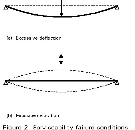
Serviceability limit states concern those states at which the structure, although standing, starts to behave in an unsatisfactory fashion due to, say, excessive deformations or vibration (Figure 2). Thus the designer would check to ensure that the structure will fulfil its function satisfactorily when subject to its service, or working, loads.
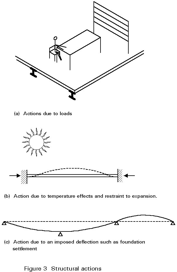
These aspects of behaviour may need to be checked under different conditions. Eurocode 3 for instance defines three design situations, corresponding to normal use of the structure, transient situations, for example during construction or repair, and accidental situations. Different actions, i.e. various load combinations and other effects such as temperature or settlement, may also need to be considered (Figure 3).
Despite the apparently large number of cases which should be considered, in many cases it will be sufficient to design on the basis of resistance and stability and then to check that the deflection limit will not be exceeded. Other limit states will clearly not apply or may be shown not to govern the design by means of quite simple calculation.
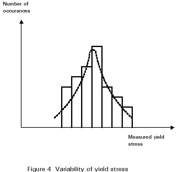
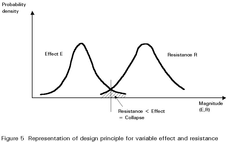
At its most basic level limit state design simply provides a framework within which explicit and separate consideration is given to a number of distinct performance requirements. It need not necessarily imply the automatic use of statistical and probabilistic concepts, partial safety factors, etc., nor of plastic design, ultimate load design, etc. Rather it is a formal procedure which recognises the inherent variability of loads, materials, construction practices, approximations made in design, etc., and attempts to take these into account in such a way that the probability of the structure becoming unfit for use is suitably small. The concept of variability is important because the steelwork designer must accept that, in performing his design calculations, he is using quantities which are not absolutely fixed or deterministic. Examples include values for loadings and the yield stress of steel which, although much less variable than the properties of some other structural materials, is known to exhibit a certain scatter (Figure 4). Account must be taken of these variations in order to ensure that the effects of loading do not exceed the resistance of the structure to collapse. This approach is represented schematically in Figure 5 which shows hypothetical frequency distribution curves for the effect of loads on a structural element and its strength or resistance. Where the two curves overlap, shown by the shaded area, the effect of the loads is greater than the resistance of the element, and the element will fail.
Proper consideration of each of the limits eliminates the inconsistencies of attempting to control deflection by limiting stresses or of avoiding yield at working load by modifying the design basis (formula, mathematical model, etc.) for an ultimate resistance determination.
The procedure of limit state design can therefore be summarised as follows:
An action on a structure may be a force or an imposed deformation, such as that due to temperature or settlement. Actions are referred to as direct and indirect actions respectively in Eurocode 3.
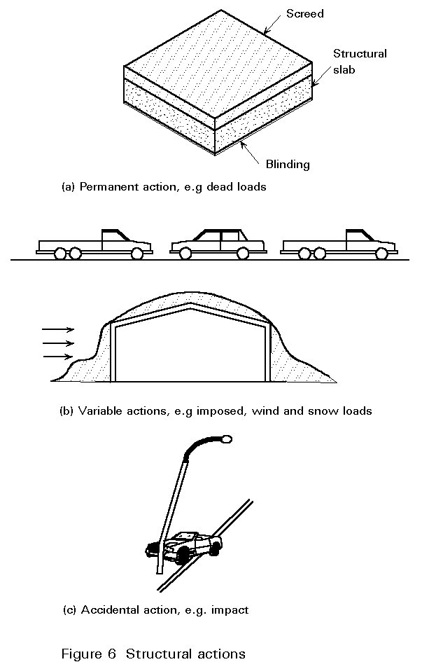
Actions may be permanent, e.g. self-weight of the structure and permanent fixtures and finishes, variable, e.g. imposed, wind and snow loads, or accidental, e.g. explosions and impact (Figure 6). For earthquake actions, see Lectures 17 and Eurocode 8 [2]. Eurocode 1 [3] represents these by the symbols G, Q and A respectively, together with a subscript - k or d to denote characteristic or design load values respectively. An action may also be classified as fixed or free depending upon whether or not it acts in a fixed position relative to the structure.
The actual loadings applied to a structure can seldom be defined with precision; liquid retaining structures may provide exceptions. To design a structure for the maximum combination of loads which could conceivably be applied would in many instances be unreasonable. A more realistic approach is to design the structure for 'characteristic loads', i.e. those which are deemed to have just acceptable probability of not being exceeded during the lifetime of the structure. The term 'characteristic load' normally refers to a load of such magnitude that statistically only a small probability, referred to as the fractile, exists of it being exceeded.
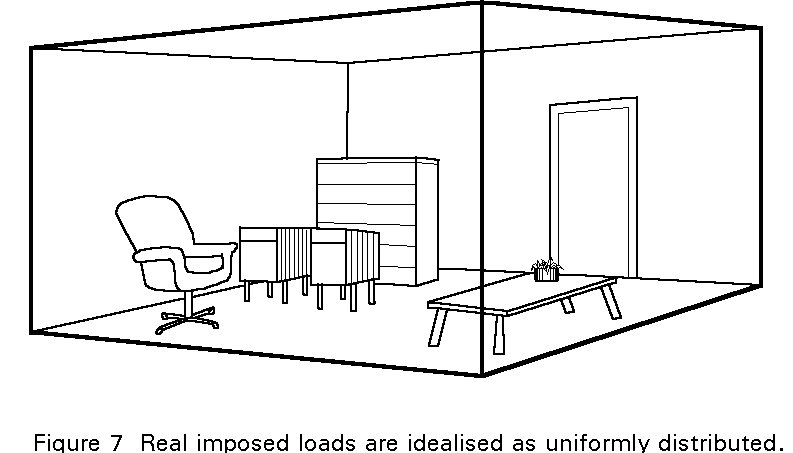
Imposed loadings are open to considerable variability and idealisation, typically being related to the type of occupancy and represented as a uniform load intensity (Figure 7). Dead loads are less variable although there is evidence that variations arising in execution and errors can be substantial, particularly in the case of in-situ concrete and finishes such as tarmac surfacing on road bridges.
Loadings due to snow, wind, etc. are highly variable. Considerable statistical data on their incidence have been collated. Consequently it is possible to predict with some degree of certainty the risk that these environmental loads will exceed a specified severity for a particular location.
The design value of an action is its characteristic value multiplied by an appropriate partial safety factor. The actual values of the partial factors to be used depend upon the design situation (normal, transient or accidental), the limit state and the particular combination of actions being considered. Corresponding values for the design effects of actions, such as internal forces and moments, stresses and deflections, are determined from the design values of the actions, geometrical data and material properties.
Variability of loading is only one aspect of uncertainty relating to structural behaviour. Another important one is the variability of the structural material which is reflected in variations in strength of the components of the structure. Again, the variability is formally accounted for by applying appropriate partial safety factors to characteristic values. For structural steel, the most important property in this context is the yield strength.
The characteristic yield strength is normally defined as that value below which only a small proportion of all values would be expected to fall. Theoretically this can only be calculated from reliable statistical data. In the case of steel, for practical reasons a nominal value, corresponding typically to the specified minimum yield strength, is generally used as the characteristic value for structural design purposes. This is the case in Eurocode 3 which tabulates nominal values of yield strength for different grades of steel.
The design value for the strength of steel is defined as the characteristic value divided by the appropriate partial safety factor. Other material properties, notably modulus of elasticity, shear modulus, Poisson's ratio, coefficient of linear thermal expansion and density, are much less variable than strength and their design values are typically quoted as deterministic.
In addition to the quantified values used directly in structural design, certain other material properties are normally specified to ensure the validity of the design procedures included within codified rules. For instance Eurocode 3 stipulates minimum requirements for the ratio of ultimate to yield strength, elongation at failure and ultimate strain if plastic analysis is to be used [1].
Geometrical data are generally represented by their nominal values. They are the values to be used for design purposes. The variability, for instance in cross-section dimensions, is accounted for in partial safety factors applied elsewhere. Other imperfections such as lack of verticality, lack of straightness, lack of fit and unavoidable minor eccentricities present in practical connections should be allowed for. They may influence the global structural analysis, the analysis of the bracing system, or the design of individual structural elements and are generally accounted for in the design rules themselves.
Instead of the traditional single factor of safety used in permissible stress design, limit state design provides for a number of partial safety factors to relate the characteristic values of loads and strength to design values. ISO Standard 2394 [4] suggests the use of seven partial safety factors but these are often combined to simplify design procedures. This is the case in the Eurocodes [1,3] which include factors for actions and resistance. Further details are given in the Appendix.
In principle, the magnitude of a partial safety factor should be related to the degree of uncertainty or variability of a particular quantity (action or material property) determined statistically. In practice, whilst this appears to be the case, the actual values of the partial safety factors used incorporate significant elements of the global safety factor and do not represent a rigorous probabilistic treatment of the uncertainties [5-8].
In essence the characteristic actions (Fk) are multiplied by the partial safety factors on loads (gF) to obtain the design loads (Fd), that is:
Fd = gf Fk
The effects of the application of the design loads to the structure, i.e. bending moment, shear force, etc. are termed the 'design effects' Ed.
The design resistance Rd is obtained by dividing the characteristic strengths Rk by the partial safety factors on material gM, modified as appropriate to take account of other considerations such as buckling. For a satisfactory design the design resistance should be greater than the 'design effect'.
The following conditions may need to be verified under appropriate design actions:
a. Ed,dst £ Ed,stb
where Ed,dst and Ed,stb are the design effects of destabilising and stabilising actions respectively. This is the ultimate limit state of static equilibrium.
b. Ed £ Rd
where Ed and Rd are the internal action and resistance respectively. In this context it may be necessary to check several aspects of an element's resistance. These aspects might include the resistance of the cross-section (as a check on local buckling and yielding), and resistance to various forms of buckling (such as overall buckling in compression, lateral-torsional buckling and shear buckling of webs), as well as a check that the structure does not transform into a mechanism.
c. no part of the structure becomes unstable due to second order effects.
d. the limit state of rupture is not induced by fatigue.
The serviceability limit state is generally concerned with ensuring that deflections are not excessive under normal conditions of use. In some cases it may also be necessary to ensure that the structure is not subject to excessive vibrations. Cases where this is particularly important include structures exposed to significant dynamic forces or those accommodating sensitive equipment. Both deflection and vibration are associated with the stiffness rather than strength of the structure.
At the serviceability limit state, the calculated deflection of a member or of a structure is seldom meaningful in itself since the design assumptions are rarely realised because, for example:
The calculated deflection is, however, valuable as an index of the stiffness of a member or structure, i.e. to assess whether adequate provision is made in relation to the limit state of deflection or local damage. For this purpose, sophisticated analytical methods are seldom justified. Whatever methods are adopted to assess the resistance and stability of a member or structure, calculations of deflection should relate to the structure of the elastic state. Thus, when analysis to check compliance with the strength limit is based on rigid-elastic or elastic-plastic concepts, the structural behaviour in the elastic phase must also be considered.
Calculated deflections should be compared with specified maximum values, which will depend upon circumstances. Eurocode 3 [1] for instance tabulates limiting vertical deflections for beams in six categories as follows:
In determining the deflection it may be necessary to consider the effects of precamber, permanent loads and variable loads separately. The design should also consider the implications of the deflection values calculated. For roofs, for instance, regardless of the limits specified in design rules, there is a clear need to maintain a minimum slope for run-off. More stringent limits may need therefore to be considered for nearly flat roof structures.
The dynamic effects to be considered at the serviceability limit state are vibration caused by machinery and self-induced vibrations, e.g. vortex shedding. Resonance can be avoided by ensuring that the natural frequencies of the structure (or any part of it) are sufficiently different from those of the excitation source. The oscillation and vibration of structures on which the public can walk should be limited to avoid significant discomfort to the users. This situation can be checked by performing a dynamic analysis and limiting the lowest natural frequency of the floor. Eurocode 3 recommends a lower limit of 3 cycles per second for floors over which people walk regularly, with a more severe limit of 5 cycles per second for floors used for dancing or jumping, such as gymnasia or dance halls [1]. An alternative method is to ensure adequate stiffness by limiting deflections to appropriate values.
No structural theory, whether elastic or plastic, can predict the load-carrying resistance of a structure in all circumstances and for all types of construction. The design of individual members and connections entails the use of an appropriate structural theory to check the mode of failure; sometimes alternative types of failure may need to be checked and these may require different types of analysis. For example, bending failure by general yielding can only occur when the plastic moment is attained; however bending failure is only possible if failure does not occur at a lower load level by either local or overall buckling.
Serviceability limit states are concerned with the performance of the structure under service loading conditions. The behaviour should therefore be checked on the basis of an elastic analysis, regardless of the model used for the ultimate limit state design.
A limit state is a condition beyond which the structure no longer satisfies the design performance requirements.
The ultimate limit state is a state associated with collapse and denotes inability to sustain increased load.
The serviceability limit state is a state beyond which specified service requirements are no longer met. It denotes loss of utility and/or a requirement for remedial action.
Characteristic loads (Gk, Qk, Ak) are those loads which have an acceptably small probability of not being exceeded during the lifetime of the structure.
The characteristic strength (fy) of a material is the specified strength below which not more than a small percentage (typically 5%) of the results of tests may be expected to fall.
Partial safety factors (g G, g Q, g M) are the factors applied to the characteristic loads, strengths, and properties of materials to take account of the probability of the loads being exceeded and the assessed design strength not being reached.
The design (or factored) load (Gd, Qd, Ad) is the characteristic load multiplied by the relevant partial safety factor.
The design strength is the characteristic strength divided by the appropriate partial safety factor for the material.
[1] Eurocode 3: "Design of Steel Structures" ENV 1993-1-1: Part 1.1: General Rules and Rules for Buildings, CEN, 1992.
[2] Eurocode 8: "Structures in Seismic Regions-Design", CEN (in preparation).
[3] Eurocode 1: "Basis of Design and Actions on Structures" CEN (in preparation).
[4] ISO 2394, General Principles for the Verification of the Safety of Structures, International Standards Organisation, 1973.
[5] Rationalisation of Safety and Serviceability Factors in Structural Codes, CIRIA Report 63, London, 1972.
[6] Allen, D. E., "Limit States Design - A Probabilistic Study", Canadian Journal of Civil Engineers, March 1975.
[7] Augusti, G., Baratta, A., and Casciati, F., "Probabilistic Methods in Structural Engineering", Chapman and Hall, London 1984.
[8] Armer, G. S. T., and Mayne, J. R, "Modern Structural Design Codes - The Case for a More Rational Format", CIB Journal Building Research and Practice, Vol. 14, No. 4, pp 212-217, 1986.
1. Pugsley, A., "The Safety of Structures", Edward Arnold, London 1966.
2. Thoft-Christensen, P., and Baker, M. J., "Structural Reliability Theory and its Application", Springer-Verlag, 1982.
3. "The Steel Skeleton", Cambridge University Press, Vol 1 1960, Vol II 1965.
4. Blockley, D., "The Nature of Structural Design and Safety", Ellis Horwood, Chichester, 1980.
5. Fukumoto, Y., Itoh, Y. and Kubo, M., "Strength Variation of Laterally Unsupported Steel Beams", ASCE, Vol 106, ST1, 1980.
6. ISO 8930: General Principles on Reliability of Structures - List of Equivalent Terms, 1987.
APPENDIX - PARTIAL SAFETY FACTORS
Partial safety factors for actions
Eurocodes 1 and 3 define three partial safety factors as follows:
g
G permanent actionsg
Q variable actionsg
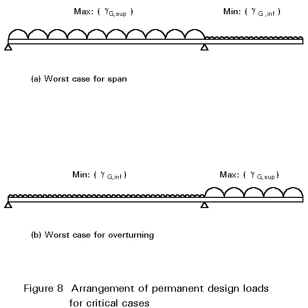
A accidental actionsTwo values are specified for gG. These are gG,sup and gG,inf representing 'upper' and 'lower' values respectively. Where permanent actions have an adverse effect on the design condition under consideration, the partial safety factor should be the upper value. However, where the effect of a permanent action is favourable (for instance in the case of loads applied to a cantilever when considering the design of the adjacent span), the lower value for the partial safety factor should be used, see Figure 8.
The treatment of load combinations is quite sophisticated, and involves the definition of 'representative' values, determined by applying a further factor to the design loads, depending upon the particular combination considered. However, simplified procedures are generally permitted. They are outlined below. Note that the values of partial safety factors are indicative only. Although they are specified in Eurocode 3, their precise value may be adjusted by individual countries for use within the country.
Load combinations for the ultimate limit state
Either, all permanent loads plus one variable load, all factored, i.e:
S
gG Gki + gQ Qk1where gG and gQ are taken as 1,35 and 1,5 respectively,
or, all permanent loads plus all variable loads, all factored, i.e:
S
gG Gki + S gQ Qkiwhere gG and gQ are both taken as 1,35.
These values recognise the reduced probability of more than one variable load existing simultaneously. For instance, although a structure may on occasions be subject to its maximum wind load, it is much less likely that it will be exposed to a combination of maximum wind and imposed loads.
Load combinations for the serviceability limit state
Either, all permanent loads plus one variable load are considered. In each case the partial safety factor is unity, i.e. the loads are unfactored characteristic values:
S
Gki + Qk1or, all permanent loads (partial safety factor unity) plus all variable loads (with a partial safety factor of 0,9), i.e:
S
Gki + 0,9 S QkiWhere simplified compliance rules are provided for serviceability, there is no need to perform detailed calculations with different load combinations.
Partial safety factors for material
Alternative partial safety factors for material are specified as follows:
g
M0 = 1,1 for consideration of resistance of Class 1, 2 or 3 cross-section.g
M2 = 1,1 for consideration of resistance of Class 4 cross-section and resistance to buckling.g
M2 = 1,25 for resistance consideration of cross-section at holes