ESDEP WG 11
CONNECTION DESIGN: STATIC LOADING
To use the design methods given in Eurocode 3 for fillet welds.
Lectures 1B.5: Introduction to Design of Buildings
Lecture 2.1: Characteristics of Iron-Carbon Alloys
Lecture 2.3: Engineering Properties of Steels
Lecture 3.2: Erection
Lecture 3.5: Fabrication/Erection of Buildings
Lecture 3.6: Inspection/Quality Assurance
Lecture 11.1.2: Introduction to Connection Design
Lecture 2.4: Steel Grades and Qualities
Lecture 2.6: Weldability of Structural Steels
Lecture 3.3: Principles of Welding
Lecture 3.4: Welding Processes
Lecture 11.4: Analysis of Connections
Lectures 11.2.1 & 11.2.2: Other lectures on Welded Connections
This lecture illustrates the design of fillet welds subject to loads of different directions. A comparison is made between the mean stress method and the alternative method in Eurocode 3 [1].
NOTATION
A cross-section area of plate [mm2]
a throat thickness of weld [mm]
b width of flange [mm]
beff effective breadth [mm]
F external load [N]
fy, fyp nominal yield stress of parent metal [MPa]
fu nominal ultimate tensile stress of parent metal [MPa]
fvw design shear strength of weld metal [MPa]
l, l2 length of fillet welds [mm]
r radius of fillet in rolled sections [mm]
t, tp thickness of plate [mm]
tf thickness of flange [mm]
tw thickness of web [mm]
b
w reduction factorg
Mw partial safety factor for weldsg
M2 partial safety factor for parent materials
1 normal stress perpendicular to the throat area of the weld [MPa]t
1 shear stress in the plane of the throat area transverse to the weld axis [MPa]t
2 shear stress in the plane of the throat area parallel to the weld axis [MPa]Lecture 11.2.2 sets out the two methods proposed in Eurocode 3 [1] for designing fillet welds, the mean stress method and the alternative method.
The mean stress method (Eurocode 3 - Clause 6.6.5.3) is a simplification of the alternative method. The welds, must satisfy
F/al £ fvw = fu/[Ö3.bwgMw] (1)
where
F is the external force (independent of orientation) transmitted by the fillet welds
a is the throat thickness
l is the length of the weld
fvw is the design shear strength of the weld.
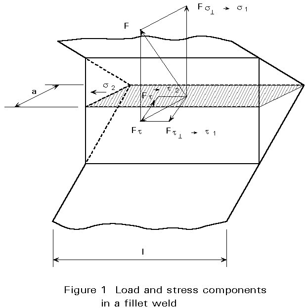
The alternative method (Eurocode 3, Annex M) requires a calculation of the different stress components in the weld to determine an equivalent stress. The following conditions must be satisfied:
Ö[s12 + 3(t12 + t22)] £ fu/[bwgMw] (2)
and s1 £ fu/gMw (3)
where
s
1, t1, and t2 are the tensile and shear stress components (see Figure 1) applied to the throat area of the weld
fu is the nominal ultimate tensile strength of the weaker part joined
g
Mw is the partial safety factor for welds = 1,25b
w is the correlation factor for which the values are:bw = 0,8 for S235 steel, (fu = 360MPa)
bw = 0,85 for S275 steel, (fu = 430MPa)
bw = 0,90 for S355 steel, (fu = 510MPa)
A comparison of designs produced by the two methods follows.
Side fillet welds transfer an axial force F applied in a direction parallel to the weld length. Consider a lap joint with two side fillet welds (Figure 2). Each weld transmits the force ![]() .
.
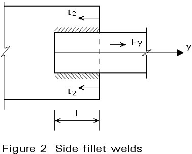
Condition (1) gives F/(2al) £ fu/[Ö3.bwgMw]
Hence, the throat thickness must satisfy
a ³ (Ö3/2)F/(ful).bwgMw (4)
With this axial force, only the stress component t2 is considered:
t2 = ![]()
s1 = t1 = 0
Condition (2) gives
Ö(3t22) = Ö3F/(2al) £ fu/(bwgMw)
and the minimum throat thickness is:
a ³ (Ö3/2)Fy/(ful).bwgMw
Condition (3) need not be considered here (s1 = 0). For side welds, the two methods lead to the same result for the throat area of the welds.
The connection can be designed by comparison to be as strong as the connected member. For this purpose it is not necessary to determine the magnitude of the force acting on the connection.
In the case of two side fillet welds transferring an axial force, the following condition for equal strength can be set:
2alfu/(Ö3.bwgMw) ³ A fy
or
a ³ Ö3Afy/(2lfu).bwgMw (5)
where
A is the cross-section area of the connected member
fy is the nominal yield strength of the member
End fillet welds transfer an axial force applied in a direction perpendicular to the weld length. Consider a tee joint with two end fillet welds (Figure 3). Each weld transmits the force ![]() .
.
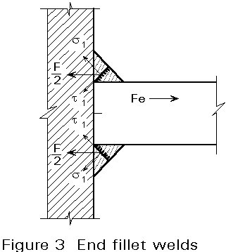
Condition (1) gives
F/(2al) £ fu/(Ö3.bwgMw)
and a ³ Ö3F/(2lfu).bwgMw (6)
Only the stress components s1 and t1 are determined in the throat area of the weld.
s1 = t1 = ![]()
t2 = 0
Using condition (2)
Ö[s12 + 3t12] £ fu/[bwgMw]
then

The minimum throat thickness for each weld is:
a ³ (Ö2/2)(F/ful)[bwgMw] (7)
Condition (3) s1 = F/(2Ö2al) £ fu/gMw
gives a ³ Fx/(2Ö2ful).gMw (7')
Comparison of (7) and (7') shows that the throat thickness given by (7) governs the choice of weld dimensions.
For end welds, the alternative method is more advantageous than the mean stress method. The reduction of the throat thickness is ![]() = 0,82.
= 0,82.
From (7) and (4) the equivalent strength for an end fillet weld few and a side fillet weld fsw according to the alternative method can easily be deduced. These values as well as condition (8) for different steel grades are given in Table 1.
|
S235 |
S275 |
S355 |
|
|
few [N/mm2] (end fillets) equal strength with two welds |
255 a ³ 0,46 t |
286 a ³ 0,48 t |
321 a ³ 0,55 t |
|
fsw [N/mm2] (side fillets) |
208 |
234 |
262 |
Table 1 Equivalent strength for end and side fillet welds for different steel grades
In the case of two end fillet welds transferring a force perpendicular to the weld length, the following condition for equal strength applies (the alternative method):
2alfu /(Ö2bwgMw) ³ t l fy
or
a ³ (Ö2/2)(tfy/fu).bw gMw (8)
where
t is the thickness of the connected member.
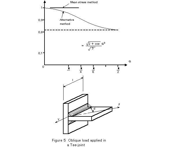
The two loading conditions described in chapters 2 and 3 occur frequently. A fillet weld may also be subject to oblique loading. Figure 4 shows some cases of oblique loaded welds.
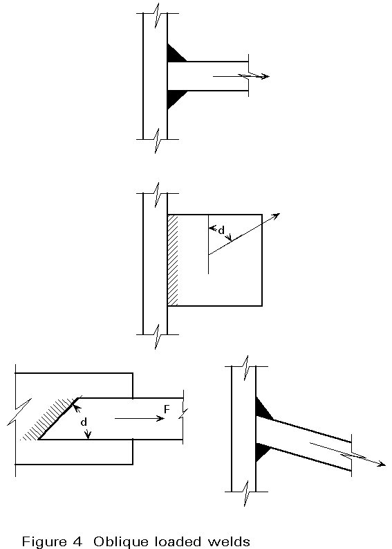
Using the mean stress method, the design of oblique loaded welds is very simple. With the alternative method the design is made as follows:
Figure 5 shows the relation between the calculated required throat thickness according to the alternative and the mean stress method for a tee-joint subject to an oblique load.
The load-deformation behaviour of fillet welds is illustrated in Figure 6. It is clear that an end fillet weld is considerably stronger than a side fillet weld. The difference is actually larger than one would expect from the calculation methods described here. One reason is that the failure plane for an end fillet weld differs from the theoretical throat plane, resulting in a larger failure area of the weld. The failure plane for a side fillet weld, however, is closer to the throat plane.
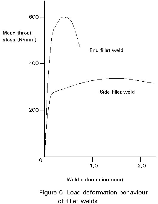
Figure 6 also shows that the ductility of an axially loaded weld is much larger than a weld loaded in the transverse direction.
If a plate is welded to an unstiffened flange of an I- or a box section, loading will tend to deform the flange or the box side unequally along the breadth. The result is that the parts of the weld near the web will be more heavily loaded than the other parts, see Figure 7. Therefore a reduced effective breadth shall be taken into account both for the parent material and for the welds.
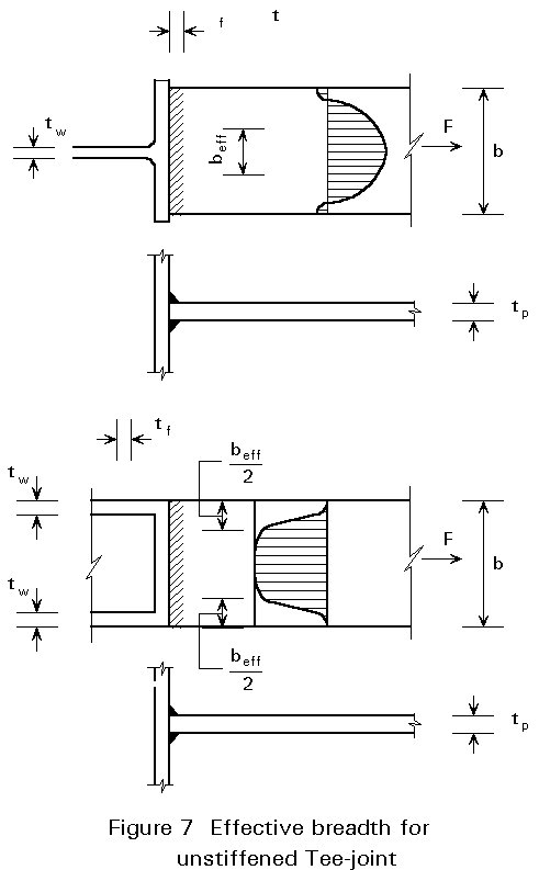
For an I-section the effective breadth beff should be taken as:
beff = tw + 2r + 7 tf (9)
but
beff = tw + 2r + 7 ![]() (10)
(10)
where
the geometrical parameters tw, r, tf and tp are shown in Figure 7.
fy is the design yield strength of the member
fyp is the design yield strength of the plate.
If beff < 0,7 b the joint should be stiffened.
For a box section the effective breadth beff should be taken as:
beff = 2tw + 5tf (11)
but
beff £ 2tw + 5 ![]() (12)
(12)
Whatever weld design method is used it is also necessary to ascertain that the base metal of the connected parts has sufficient resistance. To check the base metal three possible failures have to be considered, see Figure 8:
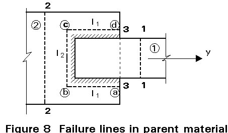
{2l1/Ö3 + l2}t2fu2 /gM2 ³ fu2 (13)
where
t2 is the thickness of member 2
fu2 is the ultimate deign strength of member 2
gM2 is the partial safety factor against ultimate = 1,25.
Note that tensile failure in the members need not be checked again in the design of the connection. The previous design of the members satisfies the strength requirements.
i) determination of the load components acting on the throat section of the fillet welds,
ii) calculation of the corresponding stress components,
iii) checking with the basic formula.
[1] Eurocode 3: "Design of Steel Structures": ENV 1993-1-1: Part 1: General rules and rules for buildings, CEN, 1992.
[1] Blodgett, O.W., "Design of welded structures", James F Lincoln Arc Welding Foundation, Cleveland, Ohio, USA, 1972.
[2] Owens, G.W. and Cheal, B.D., Structural Steelwork Connections, 1st Ed., 1989.