ESDEP WG 3
FABRICATION AND ERECTION
To explain why inspection is essential for the assurance of structural safety and to introduce the most important types of inspection - material, dimensional, welding and bolting - and the equipment used to carry it out. To define terms and generate awareness of the subject.
None.
Lecture 1B.2.1: Design Philosophies
Lectures 3.1: General Fabrication of Steel Structures
Lecture 3.3: Principles of Welding
Lecture 3.4: Welding Processes
The lecture defines the important terms used in this field. It discusses the main objectives of Inspection and Quality Assurance, which is to ensure that safety is achieved without prejudicing economy. The interrelated responsibilities of design, fabrication and inspection are defined. The main types of inspection and the most common methods of inspection are introduced with some explanation of why they are required.
The following definitions apply generally to design and manufacturing activities including those for structural steelwork:
|
Quality |
The totality of features and characteristics of a product or service that bear on its ability to satisfy a given need. |
|
Quality Assurance |
The system, including all activities, documentation and functions concerning the achievement of the required quality. |
|
Quality Control |
The operational techniques and activities that ensure the product or service quality complies with specified requirements. It is also the use of such techniques and activities. |
|
Specification |
The document that prescribes in detail, the requirements with which the product or service has to comply. |
|
Inspection |
The process of measuring, examining, testing, gauging, or otherwise comparing the item with the applicable requirements. |
|
Certification |
The authoritative act of documenting compliance with requirements. |
It will be seen from the definitions above that Inspection is an important part of Quality Control and that Quality Control and Certification is an important part of Quality Assurance.
The objectives of quality assurance in steel construction are to ensure that:
a) The quality of the design, specification and detailing are such that the requirements of the limit states are complied with most economically.
b) The quality of the materials, fabrication and erection comply with the requirements of the design.
All processes are subject to variable influences, some of which could be detrimental to structural safety or economy. For example, if a steel section is rolled much thinner than specified it could be unsafe. If it is rolled much thicker than required it would be wasteful. The dimensions of sections are never exactly the same as those in the steel sections standard.
Variations from the theoretical dimensions and material properties are due to economic limitations on control of the manufacturing process. These variations can be assessed statistically and controlled so that compliance with specifications can be assured, enabling appropriate values of gm to be selected accordingly.
Other types of variation come under the heading of gross error. These variations are rare events, but if they occur they can be very serious. For example, if a 356 x 406 Universal Column section of 287 kg/m were supplied in place of the next larger size (340 kg/m) and used undetected in the work the potential loss of strength would be about 16%. Even worse, if the grade of steel weld was Fe 275 instead of the specified Fe 350 the loss of strength would be a further 23%.
It is not economical to allow for gross error by increasing the partial safety factor for the material. The risk of gross error must be reduced to an acceptable minimum by means of adequate quality control procedures. Thus correct identification and traceability are just as important to safety as routine measurement and testing.
Quality assurance on a structural steelwork contract is the concern of:
(i) Designer/client
(ii) Material supplier/fabricator/erector
(iii) Inspector
This list is a simplified breakdown for the purpose of defining responsibility. The organisation structure depends on the type and conditions of contract. For instance the designer, fabricator and inspector might belong to one organisation and the client to another. In another case the client and designer may be the same. The inspector may or may not be employed by the fabricator.
It may be thought that the only party concerned with the attainment of adequate quality is the inspector. However, from the time when the steel is obtained to the time when the structure is completed everyone connected with the planning, design, fabrication and erection of the structure is involved with some aspect of its quality. Quality Assurance is the whole mechanism which ensures that everyone involved:
a) Knows what to do.
b) Does it.
c) Is seen to have done it.
The systems of Quality Assurance now in operation have evolved through the years. They are written down in codes of practice, standard specifications and procedures. These documents are incorporated in design and construction contracts.
The job of the inspector is primarily concerned with (c) above. Most of the time the staff concerned with design, material supply, fabrication, or erection inspect their own work, since it is their responsibility to ensure that the necessary standards are met. However, when contracts are awarded on the basis of minimum tender cost there are commercial pressures to reduce the time and hence the cost of each activity.
There is always a risk that someone:
Either does not always know what to do,
Or has insufficient time or forgets to do it,
And that the lack of some action goes undetected.
These are the prime causes of structural failure and apply equally to design, fabrication and erection operations.
It is the responsibility of the independent inspector to act as a second line of defence to reduce such aberrations to a minimum. It would clearly be uneconomical to monitor everyone's activity continuously. The act of independent inspection is therefore to measure, examine and test in such a way and at such a time that serious errors have the highest chance of being detected as early as possible and with the minimum of extra cost to production.
The importance of early detection of error or non-compliance with specification cannot be over emphasised. The consequential cost of an error remaining undetected increases exponentially with time. Errors may occur at the early stage of design which can be very serious. If the behaviour of the structure is incorrectly modelled, the stresses wrongly calculated or the wrong materials selected, the consequential cost if the structure has been erected could easily double the total cost. On the other hand, if a cracked weld is discovered and repaired prior to leaving the welding bay the economical implications are relatively small.
Independent inspection is becoming a more specialised activity as the demands of reliability increase.
Inspectors do not have a managerial or production role and are usually qualified to limited types of inspection. In the field of design they may be termed check, proof or certifying engineers rather than inspectors.
One of the most important functions of the inspector is to provide permanent evidence of compliance with the necessary quality specifications. This requirement may be in a number of ways, the most common being:
(i) Writing a report.
(ii) Witnessing an activity and signing a certificate of compliance.
(iii) Marking a component with a permanent and unique identification mark.
In the design, the most important types of inspection are concerned with checking that the dimensions are consistent with satisfactory operations and that the materials, strengths and deflections are within the limits allowed by the relevant codes of practice. The calculations form the main basis for compliance and the check is often done by a third party.
These checks involve examination of drawings, specifications, calculations and computer program listings.
The manufacture of basic components such as steel sections and plates, bolts and welding consumables requires the following checks, which are usually made at the manufacturer's works:
(i) Identification of batch.
(ii) Chemical analysis.
(iii) Mechanical testing.
(iv) Dimensional checks - external, internal.
A certificate of conformity is signed by the Inspector who carried out or witnesses the checks, which are normally made on the finished product.
At the fabrication and erection stages, when the basic components are being assembled into larger more complex units, it is not practical to carry out chemical analysis or mechanical testing of the work itself. This particularly applies in the case of welded joints where the act of welding can alter the chemistry and physical properties of the original materials. In this case reliance is placed on the checks of the welding process against specification followed by NDT (non-destructive testing) procedures.
In Section 4.4 the importance of the timing of inspections was emphasised. There are many stages of inspection on structural steelwork contracts. The most important are at:
(i) Completion of calculations.
(ii) Completion of working drawings.
(iii) Completion of shop drawings.
(iv) Manufacture of basic products.
(v) Delivery to and removal from store.
(vi) Procedure trials.
(vii) Operator qualification tests (particularly welding).
(viii) Completion of preparation of materials (cutting, drilling, etc.).
(ix) Completion of jigging, and fitting up of components.
(x) Completion of shop assembly (welding, etc.).
(xi) Completion of preparation for protective coating.
(xii) Completion of protection coating.
(xiii) Completion of assembly on site.
(xiv) Completion of erection on site.
Most of the above stages of inspection are carried out at the end of a particular phase at the place of work. Thus any deficiencies can be rectified with the minimum cost and delay to the programme.
Conformance to a planned programme of work is also an important feature of quality assurance.
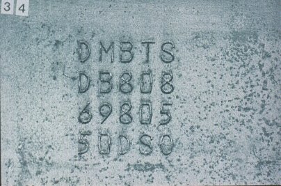
Steel plates and sections are identified by the cast number. Individual pieces are marked permanently by hardstamping or indelible painting. When lengths are cut these marks must be transferred to all cut pieces apart from those used for scrap.
Slide 1
Slide 1 : Identification mark on rolled plate
Small manufactured components such as bolts or welding rods usually have the standard or grade to which they are made embossed or marked on each item. The batch number is marked on the bag or container in which they are supplied.
Structural components are given identification numbers by the fabricator. Identical members usually have the same mark to avoid unnecessary complexity.
All materials and components should be traceable back to source at any stage of the project.
Drawings and revisions to them should be clearly identified and superseded issues withdrawn from the shop.
Test certificates should have an unique identification number.
The first requirement for the acceptance of a product is that its identification mark can be traced back to and matched against that on a source document such as a certificate or drawing, etc.
Checks on chemical analysis are an important part of quality control. The analysis of steel is normally carried out for each cast. Levels of carbon and manganese have a direct bearing on strength.
Levels of chromium, molybdenum, vanadium, nickel and copper are also taken into account in measuring weldability by the use of the Carbon Equivalent Formula. A check of these levels is vital to the preparation of welding procedures (see Lecture 3.4). Levels of sulphur and phosphorus should also be controlled to ensure ductility and weldability.
Most structural steel specifications have defined limits of carbon, manganese, sulphur and phosphorus. The cast analysis is shown on the mill test certificate.
Slide 2
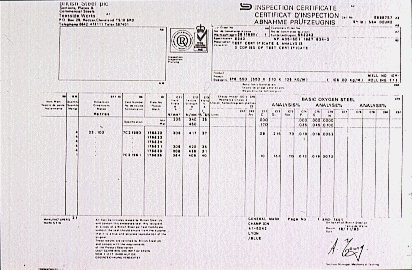
Slide 2 : Typical mill certificate detailing cast analysis
Welding consumables are supplied to a specified analysis.
Analysis of steels by X-ray spectrometry is usually carried out at the steel mill.
Paints are subject to specialist analysis to ensure consistency from batch to batch.
The most important mechanical test is the tensile test. This test is carried out by the steel supplier on each batch of a particular cast, product form and grade. A typical batch may be 40 to 50 tonnes. The tensile specimen, Slide 3, is machined from a corner of the product and tested to destruction. The load and extension is measured. The resulting yield stress, Slide 4, ultimate stress and elongation (or reduction of area) are recorded on the test certificate.
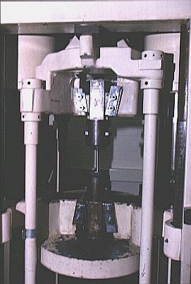
Slide 3 : Typical tensile test
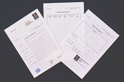
Slide 4 : Tensile test certificate
Another important mechanical test is the Charpy V-notch test to assess the notch-ductility of the steel at the relevant temperature, Slides 5 and 6. This test must be carried out at the prescribed temperature which may vary from Room Temperature (+20°C) to -50°C or 60°C depending on the specified toughness grade. The requirement is that the energy absorption is not less than the specified minimum energy at the test temperature (usually 27 Joules). The specimen orientation, location and machining are carefully specified. The temperature is usually obtained by use of carbon dioxide 'ice'.
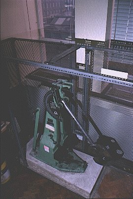
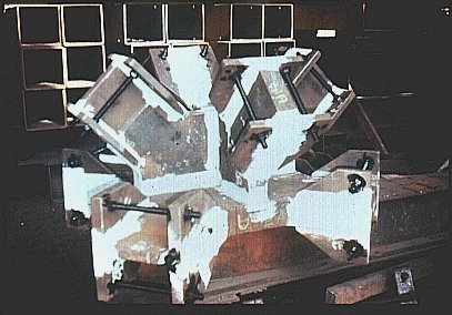
Slide 5 : Charpy test machine
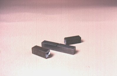
Slide 6 : Charpy test specimen
Other material tests include the through-thickness ductility test, for determining the resistance to lamellar tearing, the bend test for butt welds, the nick break test for fillet welds and a bend test for shear connectors, Slide 7.
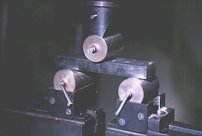
Slide 7 : Bend test
The quality of trial welds is usually assessed by taking a macro-section through the weld. This section is then polished and etched to reveal the fusion boundary and heat affected zone (HAZ). A hardness survey is then done to find the peak hardness. This survey involves pressing a diamond pyramid pointer into the surface using a specified force and measuring the size of the diamond indentation, Slide 8. Specifications often limit the allowable hardness to about 350 Vickers for HAZs in welds and flame cut edges.
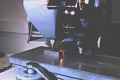
Slide 8 : Hardness test
For butt welds in some structures it may be required that production tests are made on coupon plates which are extensions of the weld in the structural joint. These coupons are of the same material as the structure and are welded at the same time. They are subsequently cut off the end of the joint and subjected to appropriate mechanical tests.
External
A range of simple tools is used to check dimensional accuracy, Slide 9.
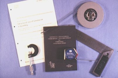
Slide 9 : Principal tools for checking dimensional accuracy
Thicknesses of plates may be checked with a micrometre gauge. Lengths and cross-sections are checked with steel tapes.
Straightness of beams and columns are checked with a line pulled taut between the ends. The departure from the straight is measured between the side of the member and the line at different positions along the member.
Flatness of plate elements is checked with a steel or aluminium straight edge and a feeler or dial gauge.
Angles are measured with a protractor or, in the case of shallow angles, they are measured as the slope (cotangent) of the angle, e.g. 1 in 20, 1 in 10, etc.
On site, levels are checked with a surveryor's automatic level and, for short lengths, by a spirit level. Columns are plumbed with a theodolite or a vertical plumb line.
Fit up of machined parts is checked with a set of feeler gauges or a taper feeler gauge.
The purposes of dimensional checks are to ensure operational acceptability and satisfactory appearance, and to ensure proper fit-up, assembly and erection.
Acceptance is on the basis of the tolerances specified on the drawings or in the specification, Slide 10.
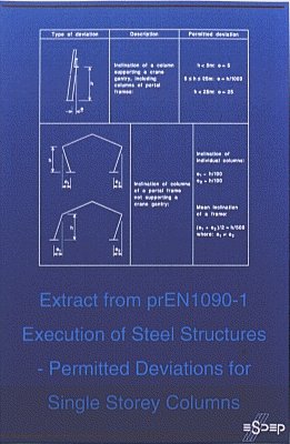
Slide 10 : Extract from a typical specification
Internal (NDT)
Ultrasonic detection, Slide 11
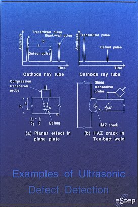
Slide 11 : Examples of ultrasonic defect detection
For critical work the internal quality of the steel products may have to be checked for freedom from rolling defects such as laminations. This check is made by means of an ultrasonic probe which sends out a beam of high frequency sound, usually at about 2MHz frequency. Any planar discontinuity in the plate sends back a reflection to the probe. The time taken to travel to and from the discontinuity is displayed on the flaw detector cathode ray screen in its x-axis. The magnitude of the return signal gives some indication of the severity of the discontinuity. This is displayed in the y-axis.
The same principle can be applied to welded joints. The only difference is that the geometry restricts the location of the probe, which must always be on a smooth surface to ensure adequate transmission of the ultrasound waves. Butt welds are checked with this technique and measurements of defect size has now been highly developed using computerised systems. It is very sensitive to small discontinuities and thus is a good technique for detection. Its main drawbacks are that characterisation of discontinuities is a subjective skill, and that its capability for sizing is limited (height 3-4mm, length 5mm).
An angled probe is generally used for welds.
Radiography, Slide 12
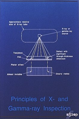
Slide 12 : Principles of X and Gamma-Ray inspection
This method is also used for weld inspection. It has the advantage of producing a permanent record on photographic film. The film is placed on the opposite side of the joint from the X-ray source. The technique gives a better picture of the quality of the weld but it has distinct disadvantages compared with ultrasonic testing:
Its use in structural work tends to be limited compared to ultrasonics.
This technique is used for finding very tight cracks at or very near the surface which cannot be seen with the naked eye. It works on the principle of applying a magnetic flux to the joint using a permanent magnet or an electromagnet. A solution containing iron filings is sprayed onto the surface which congregate around any break in the magnetic flux such as may be induced by a crack. It is quick to use but does not leave a permanent record unless photographed.
Magnetic Particle Inspection can also be used for detecting cracks at flame cut edges and cold-formed bends.
Slide 13 : Magnetic particle inspection
Penetrant Dyes
These are used for the same purposes as MPI except that they cannot detect any dyes which does not actually break the surface. The principle is to spray a coloured dye on the surface which is then absorbed into the crack. The surface is then cleaned and a thin layer of chalk sprayed over it. The dye is then drawn out of the crack into the surrounding chalk.
MPI and penetrant dyes can estimate the length of a crack, but not its depth.
Various standards on testing and inspection (International, European and National) are also available and should be referred to.