ESDEP WG 3
FABRICATION AND ERECTION
To review the welding processes commonly used in construction and to highlight some practical considerations.
Lectures 3.3: Principles of Welding
This lecture describes the welding processes commonly used in construction: Manual Metal Arc Welding, Dip and Spray Transfer Metal Active Gas Welding, Submerged Arc Welding and Stud Welding. Each process is briefly described and its advantages, disadvantages and limitations of use are summarised. Choice of welding process for a particular situation is discussed.
MAG Metal Active Gas Welding (sometimes referred to as MIG: Metal Inert Gas Welding)
MMA Manual Metal Arc Welding
SAW Submerged Arc Welding
There are three principal methods used to generate the heat required for welding:
Each method produces a pool of molten steel which must be protected against atmospheric contamination. The method used to achieve this, i.e. the shielding technique, has a major influence on the characteristics of the process. For constructional steelwork, the processes used are usually based upon the electric arc.
In arc welding, a flux or a non-reactive (inert) gas can be used to 'blanket' the weld pool and thus exclude air. This lecture is particularly concerned with the four arc welding processes commonly used in structural work.
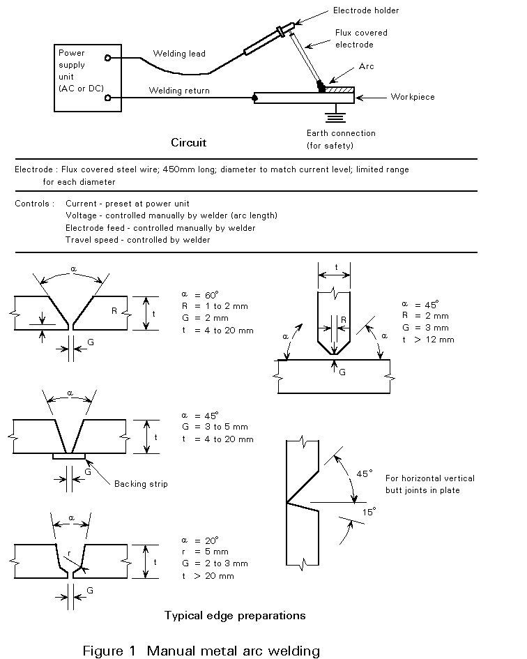
This manual method is one of the most widely used arc welding processes (see Figure 1). It requires considerable skill to produce good quality welds. The electrode consists of a steel core wire and a covering flux containing alloying elements, e.g. manganese and silicon. The arc melts the parent metal and the electrode. As metal is transferred from the end of the core wire to the weld pool, the welder moves the electrode to keep the arc length constant. This is essential as the width of the weld run is largely governed by the arc length. The flux melts with the core wire and flows over the surface of the pool to form a slag, which must be removed after solidification.
MMA has many advantages as follows:
Its main drawback is a low duty cycle, i.e. only a small volume of metal is deposited before the welder has to stop and insert another electrode. This is not a problem on short welds but becomes a consideration on long welds, especially when labour costs are high.
The operating characteristics of the electrode are controlled by the composition of the flux covering. A variety of electrodes are available to suit different applications. The current used is chosen to match the diameter of wire being used. When low hydrogen contents in the weld pool are necessary to avoid cracks in the heat-affected zone (HAZ) on cooling, MMA electrodes must be baked and stored at temperatures and times recommended by the manufacturer. These procedures ensure that the electrodes deposit weld metal with appropriate low levels of diffusible hydrogen.
This process is sometimes referred to as Metal Inert Gas (MIG) Welding, although strictly speaking the term MIG should be limited to the use of pure argon as a shielding gas, which is not used for carbon steel.
MAG is a semi-automatic process where the welding gun at the end of a flexible conduit can be hand held and manipulated, but all other operations are automatic (see Figure 2).
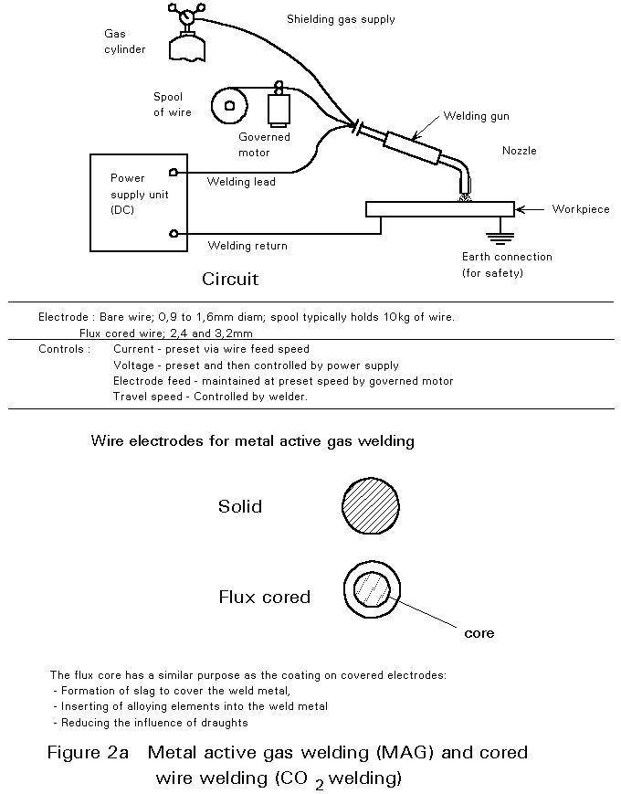
The arc and weld pool are shielded by a gas which does not react with molten steel; in current practice the shielding gas is carbon dioxide, or a mixture of argon and carbon dioxide. No flux is necessary to shield the pool since the alloying elements are in the electrode wire, but sometimes a flux-cored electrode is used to produce a slag which controls the weld profile and reduces the liability of lack of fusion defects and the incidence of porosity. The arc length is controlled by the power supply unit. Although MAG welding is somewhat easier to use than MMA, skill is required to set up the correct welding conditions.
The way in which metal is transferred from the electrode wire to the molten pool depends upon current, voltage and shielding gas composition. As the current is increased the form of the transfer changes abruptly to a stream of fine drops which are propelled across the arc gap by the electro-magnetic forces in the arc. This is called spray transfer and it enables welding to be carried out against gravity. Changing the shielding gas to carbon dioxide (assuming steel electrodes) causes the transfer to become more globular and less well directed; however, the situation can be reversed by using a mixture of inert gas and carbon dioxide.
When using steel electrodes, decreasing the arc voltage markedly and also reducing current (by reducing the wire feed rate) results in a form of transfer known as dip transfer or short-circuit transfer. In this mode of transfer metal is fused directly into the pool without passing freely across the arc gap. At slightly higher voltages the transfer is across a gap but is in larger globules without the pronounced directionality of the spray transfer. The globular to spray change is less marked with steel than with certain other metals. Welds in steel are sometimes made in which this type of transfer predominates. It is also possible to control the type of metal transfer at low to medium currents by using a special power source which delivers pulsed current to the arc.
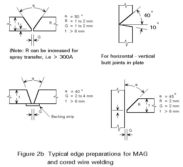
For 'positional' welding, i.e. vertical and overhead, the current must be kept below 180 amp (so that welding takes place in the 'Dip Transfer' mode) and welding speeds are comparable with MMA. Overall times for a joint, and hence productivity, are better since there is no need to deslag or change electrode. In the flat position, currents up to 400 amp ('Spray Transfer') can be used to give high welding speeds. MAG welding is especially suitable for fillet welded joints, e.g. beam to column and stiffener to panel connections. It is not easy to use on site because of problems of equipment movement and the need to provide screens to avoid loss of the gas shield in draughty conditions.
This is a fully mechanised process in which the welding head travels along the joint automatically (Figure 3). The electrode is a bare wire which is advanced by a governed motor. The voltage and current are selected at the beginning of the weld and are maintained at the pre-selected values by feed-back systems which, in practice, vary in sophistication. The flux is in the form of particles and is placed on the surface of the joint. The arc operates below the surface of the flux, melting a proportion of it to form a slag. Unfused flux is collected and may be re-used for the next weld.
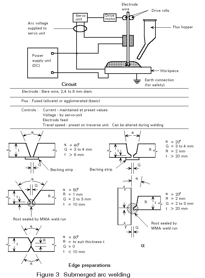
Submerged arc welding is generally operated at currents of between 400 and 1000 amps. This means that weld pools are large and can only be controlled in the flat position, although fillets can be deposited in the horizontal-vertical position up to 10mm leg length in one run. Where it is difficult to control penetration in a root run a backing strip may be used; alternatively, the root run can be made by MMA or MAG and the groove filled with SAW. SAW offers considerable advantages when welding long joints (i.e. those in excess of one metre in length). The high welding speeds and continuous operation lead to high productivity. An accurate joint fit-up is, however, a prime requirement.
This is a variation of arc welding in which studs are welded to plane surfaces automatically (Figure 4). The stud, which may be a plain or threaded bar (if plain it will have a head) is the electrode and it is held in the chuck of a welding gun which is connected to the power supply. The stud is first touched onto the surface of the steel plate or section. As soon as the current is switched on, the stud is moved away automatically to establish an arc. When a weld pool has formed and the end of the stud is molten, the latter is automatically forced into the steel plate and the current is switched off. The molten metal which is expelled from the interface is formed into a fillet by a ceramic collar which is placed around the stud arc at the beginning of the operation. This ferrule also provides sufficient protection against atmospheric contamination.
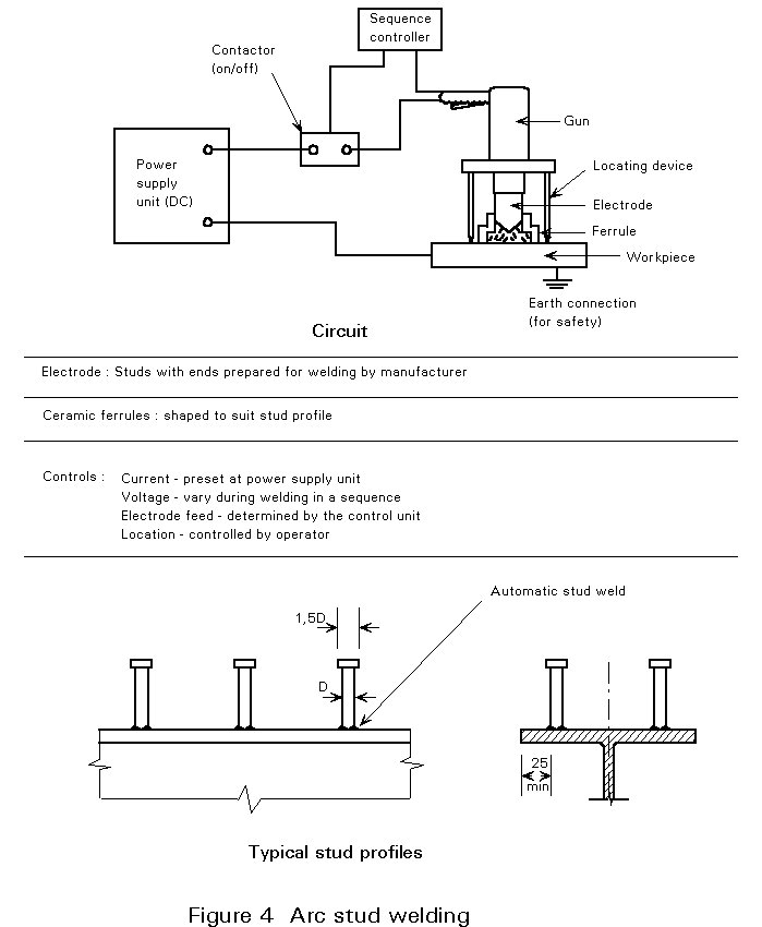
Stud welding offers an accurate and fast method of attaching shear connectors, etc., with the minimum of distortion. Whilst it requires some skill to set up the weld parameters (voltage, current, arc time and force), the operation of the equipment is relatively straightforward.
When choosing a welding process a number of factors must be taken into account:
× description of processes.
× details of individual processes.