
ESDEP WG 2
APPLIED METALLURGY
To introduce important aspects of the metallurgy of steel required for the understanding of the engineering properties of steel.
None.
Lecture 2.2: Manufacturing and Forming Processes
Lecture 2.3.1: Introduction to Engineering Properties of Steels
Lecture 2.3.2: Advanced Engineering Properties of Steels
Lecture 2.4: Steel Grades and Qualities
Lecture 2.6: Weldability of Structural Steels
This lecture commences with a discussion of the need for civil and structural engineers to have a basic knowledge of the metallurgy of steel. Then the crystalline nature of irons and steels is described together with the influence of grain size and composition on properties. The ability of iron to have more than one crystalline structure (its allotropy) and the properties of the principal crystalline forms of alloys of iron and carbon are discussed.
The metallurgy and properties of slowly cooled steels are reviewed, including the influence of grain size, rolling, subsequent heat treatment and inclusion shape and distribution. Rapidly cooled steels are treated separately; a brief description of quenching and tempering is followed by a discussion of the influence of welding on the local thermal history. Hardenability, weldability and control of cracking are briefly discussed. Finally the importance of manganese as an alloying element is introduced.
The engineering properties of steel, i.e. strength, ductility and resistance against brittle fracture, depend on its crystalline structure, grain size and other metallurgical characteristics.
These microstructural properties are dependent on the chemical composition and on the temperature-deformation history of the steel. Heat treatments that occur during welding may also have a large influence on the engineering properties.
When selecting steel for welded structures, it is important to have at least a basic knowledge of metallurgy. This knowledge is required especially when large and complicated structures are being designed, such as bridges, offshore structures, and high rise buildings.
Selecting materials, welding processes and welding consumables usually requires consultation of "real" metallurgists and welding specialists. A basic knowledge of metallurgy is essential for communication with these specialists.
Finally, a basic knowledge of metallurgy also enables civil and structural engineers to have a better understanding of the engineering properties of steel and the performance of welded structures.
Lecture 2.1 deals with the characteristics of iron-carbon alloys. Where possible, direct links are indicated to the engineering properties and weldability of steel. These subjects are covered in Lectures 2.2 and 2.6 respectively.
Lecture 2.3 describes steelmaking and the forming of steel into plates and sections. The various processes for controlling the chemical composition and the different temperature-deformation treatments are discussed. Most of the underlying principles described in Lecture 2.1 are applied.
Steels are available in various grades and qualities. The grade designates the strength properties (yield strength and ultimate strength), while the quality is mainly related to resistance against brittle fracture. Grades and qualities are explained in Lecture 2.4. A system for choosing the right quality according to Eurocode 3 (Annex C) [1] is presented. Some guidelines for the selection of steel grade are given.
To get an impression of the metallurgical structure of steel, a piece of steel bar can be cut to expose a longitudinal section, the exposed surface ground and polished and examined under a microscope.
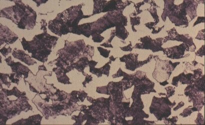
At modest magnifications, a few particles are seen which are extended in the direction of rolling of the bar, see Slide 1. These particles are inclusions. They are non-metallic substances which have become entrained within the metal during its manufacture, mostly by accident but sometimes by design. Their presence does not affect the strength but has an adverse effect on ductility and toughness. Particular types of inclusion can greatly enhance the machinability of steels and may therefore be introduced deliberately.
Slide 1 : Longitudinal stringers of inclusions in hot rolled steel. (x 500)
To reveal the true structure of the metal, the polished surface must be chemically etched. When this is done, a wide diversity of microstructure may be seen which reflects the composition of the steel and its processing, see Slides 2 - 5.
The microstructure has a significant effect on the engineering properties as described in later sections of this lecture.
Steels and cast irons are alloys of iron (Fe) with carbon (C) and various other elements, some of them being unavoidable impurities whilst others are added deliberately.
Carbon exerts the most significant effect on the microstructure of the material and its properties. Steels usually contain less than 1% carbon by weight. Structural steels contain less than 0,25% carbon: the other principal alloying element is manganese, which is added in amounts up to about 1,5%. Further alloying elements are chromium (Cr), nickel (Ni), molybdenum (Mo) etc. Elements such as sulphur (S), phosphorus, (P), nitrogen (N) and hydrogen (H) usually have an adverse effect on the engineering properties and during the steel production, measures are taken to reduce their contents. Cast irons generally contain about 4% carbon. This very high content of carbon makes their microstructure and mechanical properties very different from those of steels.
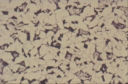
Each of the microstructures shown in Slides 2, 3, 4 and 5 is an assembly of smaller constituents. For example, the 0,2% C steel of Slide 2 is predominantly an aggregate of small, polyhedral grains, in this case <20mm in size. Closer examination of one of these grains shows it to be a single crystal. However, unlike crystals of quartz or silicon or copper sulphate, crystals of iron (Fe) are soft and ductile. The internal structure of these crystals is discussed later.
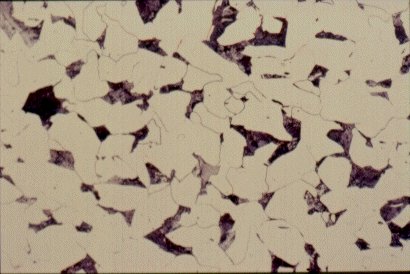
Slide 2 : Microstructure of hot rolled steel containing 0,2% carbon showing ferrite (white) and pearlite colonies (dark). (x 200)
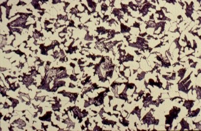
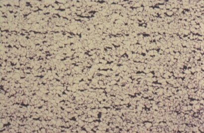
Slide 3 : Microstructure of hot rolled steel containing 0,36% carbon showing increased proportions of pearlite (dark). (x 500)
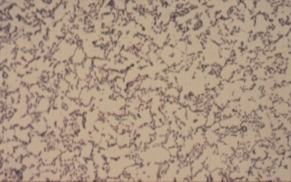
Slide 4 : Microstructure of heat treated hot rolled steel containing 0,36% carbon showing spheroidised pearlite (dark) in a ferrite matrix. (x 750)
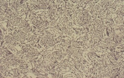
Slide 5 : Microstructure of quenched hot rolled steel containing 0,36% carbon showing bainite (x 200)
The steel of Slide 2 is an example of a polycrystalline substance which has been made visible by polishing and etching.
(a) The surface is polished but not etched.
(b) The surface is polished and etched. Different reflections of the light indicate different orientation of crystals (polycrystalline structure).
(c) Some etchants affect only the grain boundaries. These etchants are used when it is required to investigate the grain structure, e.g. to estimate the grain size.
(d) The appearance of etched grain boundaries of Figure 1c.
(e) The appearance of a steel with 0,15% carbon (enlargement 100x). The dark areas are pearlite. The grain boundaries are clearly indicated. The dark areas indicate the presence of carbon.
By adjusting the history of rolling and heating treatment experienced by the steel during its production, the grain size can be altered. This technique is useful because the grain size affects the properties. In particular, the yield strength is determined by the grain size, according to the so-called Petch equation:
sy = so + kd-1/2
where sy is the yield strength
so is effectively the yield strength of a very large isolated crystal: for mild steel this is » 50N/mm2
d is the grain size in mm
k is a material constant, which for mild steel is about 20N/mm-3/2
Thus, if the grain size is 0.01 mm, sy » 250N/mm2.
The internal structure of the crystal grains is composed of iron atoms arranged according to a regular three-dimensional pattern. The pattern is illustrated in Figure 2. This pattern is the body-centred cubic crystal structure; atoms are found at the corners of the cube and at its centre. The unit cell is only 0,28nm along its edges. A typical grain is composed of about 1015 repetitions of this unit.
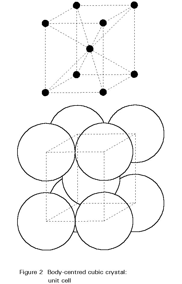
This crystal structure of iron at ambient temperature is one of the major factors determining the metallurgy and properties of steels.
Steels contain carbon. Some of it, a very small amount, is contained within the crystals of iron. The carbon atoms are very small and can fit, with some distortion, into the larger gaps between the iron atoms. This arrangement forms what is known as an interstitial solid solution: the carbon is located in the interstices of the iron crystal.
In the steels of Slides 2, 3 and 4, most of the remaining carbon has formed a chemical compound with the iron, Fe3C, iron carbide or cementite. Iron carbide is also crystalline but it is hard and brittle. With 0,1%C, there is only a small amount of Fe3C in steel. The properties of such steel are similar to those of pure iron) [2]. It is ductile but not particularly strong and is used for many purposes where ability to be shaped by bending or folding is the dominant requirement.
For a steel of higher carbon content, say 0,4%, as shown in Slide 5, a low magnification shows it to be composed of light and dark regions - about 50:50 in this case. The light regions are iron crystals containing very little dissolved carbon, as in the low carbon steel. The dark regions need closer examination. Slide 6 shows one such region at higher magnification. It is seen to be composed of alternate layers of two substances, iron and Fe3C. The spacing of the laminae is often close to the wavelength of light and consequently the etched structure can act as a diffraction grating, giving optical effects which appear as a pearl-like iridescence. Consequently, this mixture or iron and iron carbide has acquired the name 'pearlite'. The origin of the pearlite and its effect on the properties of steel are revealed by examining what happens during heating and cooling of steel.
Slide 6 : Polycrystalline structure of steel containing 0,4% carbon. (x 400)
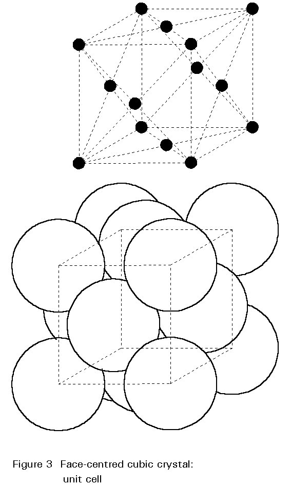
The crystal structure of steel changes with increasing temperature. For pure iron this change occurs at 910° C. The body-centred cubic (bcc) crystals of Figure 2 change to face-centred cubic (fcc) crystals as illustrated in Figure 3. For fcc crystals the atoms of iron are on the cube corners and at the centres of each face of the cube. The body-centred position is empty.
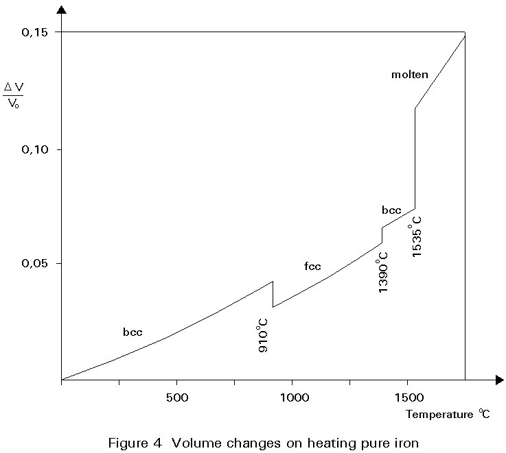
A given number of atoms occupy slightly less volume when arranged as fcc crystals than when arranged as bcc crystals. Thus the change of the crystal structure is accompanied by a volume change. This change is illustrated in Figure 4. When a piece of pure iron is heated, expansion occurs in the normal way until the temperature of 910° C is reached. At this temperature there is a step contraction of about ½% in volume associated with the transformation from the bcc to fcc crystal structure. Further heating gives further thermal expansion until, at about 1400°C the fcc structure reverts to the bcc form and there is a step expansion which restores the volume lost at 910°C. Heating beyond 1400°C gives thermal expansion until melting occurs at 1540°C. The curve is reversible on cooling slowly.
The property that metals may have different crystal structures, depending on temperature, is called allotropy.
When the atoms of two materials A and B have about the same size, crystal structures may be formed where a number of the A atoms are replaced by B atoms. Such a solution is called substitutional because one atom substitutes for the other. An example is nickel in steel.
When the atoms of two materials have a different size, the smaller atom may be able to fit between the bigger atoms. Such a solution is called interstitial. The most familiar example is the solution of carbon in iron. In this way the high temperature fcc crystals can contain up to 2% solid solution carbon at 1130°C, while in the low temperature bcc crystals, the maximum amount of carbon which can be held in solution is 0,02% at 723°C and about 0,002% at ambient temperature.
Thus a steel containing 0,5% carbon, for example, can dissolve all the carbon in the higher temperature fcc crystals but on cooling cannot maintain all the carbon in solution in the bcc crystals. The surplus of carbon reacts with iron to form iron carbide (Fe3C), usually called cementite. Cementite is hard and brittle compared to pure iron.
The amount of cementite and the distribution of cementite particles in the microstructure is important for the engineering properties of steel.
The distribution of cementite is highly dependent on the cooling rate. The distribution may be explained by considering the so-called iron-carbon phase diagram, see Section 3.4.
The following nomenclature is used by the metallurgist:
|
Ferrite or a -Fe |
The bcc form of iron in which up to 0,02%C by weight may be dissolved. |
|
Cementite |
Iron carbide Fe3C (which contains about 6,67%C). |
|
Pearlite |
The laminar mixture of ferrite and cementite described earlier. The overall carbon content of the mixture is 0,8% by weight. |
|
Austenite or g -Fe |
The fcc form of iron which exists at high temperatures and which can contain up to approximately 2%C by weight. |
|
Steel |
Alloys containing less than 2% carbon by weight. |
|
Cast Iron |
Alloys containing more than 2% carbon by weight. |
Steel used in structures such as bridges, buildings and ships, usually contains between 0,1% and 0,25% carbon by weight.
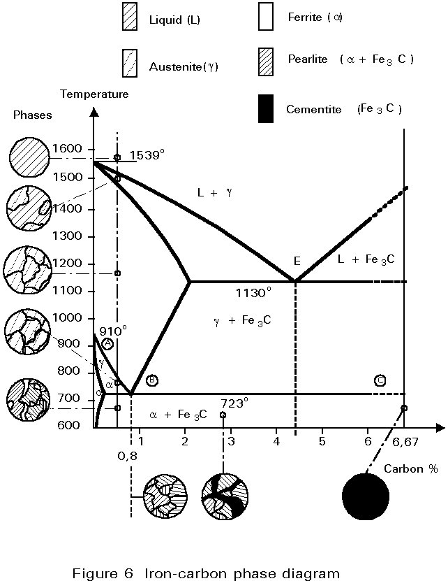
The iron-carbon phase diagram is essentially a map. The most important part is shown in Figure 5. More details are given in Figure 6.
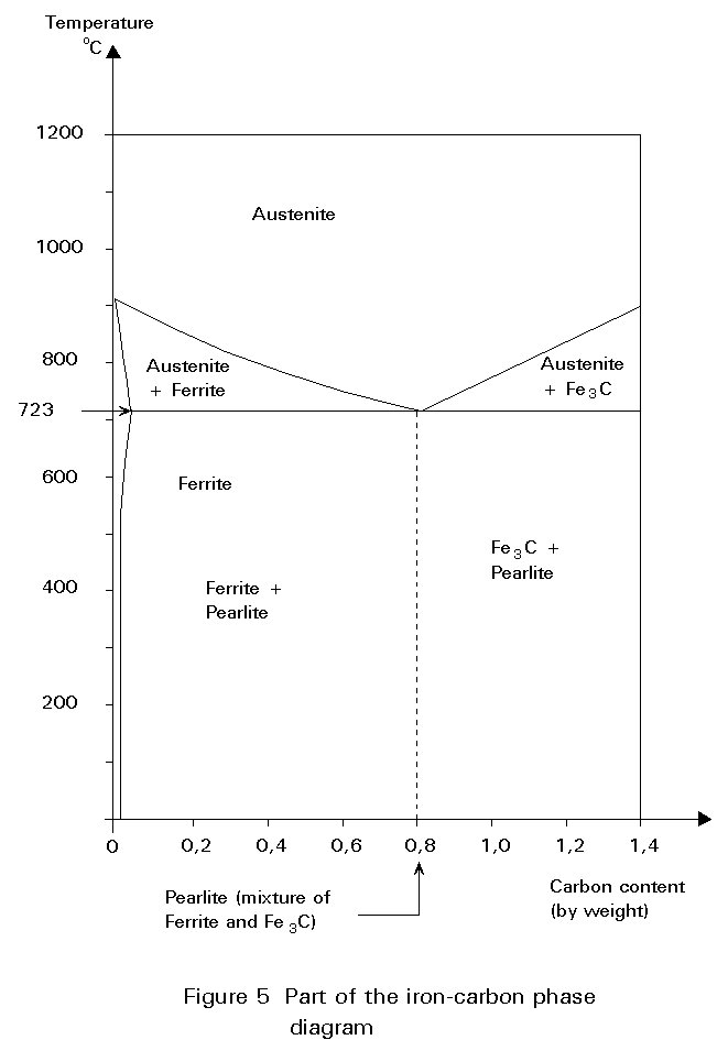
Any point in the field of the diagram represents a steel containing a particular carbon content at a particular temperature.
The diagram is divided into areas showing the structures that are stable at particular compositions and temperatures.
The diagram may be used to consider what happens when a steel of 0,5%C is cooled from 1000°C (Figure 6).
At 1000°C the structure is austenite, i.e. polycrystalline fcc crystals with all the carbon dissolved in them. No change occurs on cooling until the temperature reaches about 800°C. At this temperature, a boundary is crossed from the field labelled Austenite (g) to the field labelled Ferrite + Austenite (a + g), i.e. some crystals of bcc iron, containing very little carbon, begin to form from the fcc iron. Because the ferrite contains so little carbon, the carbon left must concentrate in the residual austenite. The carbon content of the austenite and the relative proportions of ferrite and austenite in the microstructure adjust themselves to maintain the original overall carbon content.
These quantities may be worked out by considering the expanded part of the iron-carbon diagram shown in Figure 7. Imagine that the steel has cooled to 750°C. The combination of overall carbon content and temperature is represented by point X.
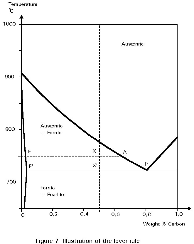
All the constituents of the microstructure are at the same temperature. A line of constant temperature may be drawn through X. It cuts the boundaries of the austenite and ferrite field at F and A. These intercepts give the carbon contents of ferrite and austenite respectively at the particular temperature.
If, now, the line FA is envisaged as a rigid beam which can rotate about a fulcrum at X, the 'weight' of austenite hanging at A must balance the 'weight' of ferrite hanging at F. This is the so-called Lever Rule:
Weight of ferrite ´ FX = Weight of austenite ´ AX
The ratio of ferrite to austenite in the microstructure is then given by:
![]()
Thus, as the steel cools, the proportion of ferrite increases and the carbon content of the remaining austenite increases, until cooling reaches 723°C. At this temperature the carbon content of the austenite is 0,8% and it can take no more. Cooling to just below this temperature causes the austenite to decompose. It decomposes into the lamellar mixture of ferrite and Fe3C identified earlier as pearlite.
The proportions of ferrite and pearlite in the microstructure, say at 722°C, are virtually the same as the proportions of ferrite and austenite immediately before the decomposition at 723°C. Thus, referring to Figure 7 and using the Lever Rule:
Weight of ferrite ´ F¢ X¢ = Weight of pearlite ´ F¢ P
In this case, there should be about twice as much pearlite as ferrite.
For other steels containing less than 0,8%C, the explanation is identical except for the proportions of pearlite in the microstructure below 723°C. This varies approximately linearly with carbon content between zero at 0,02%C and 100% at 0,8%C. A typical mild steel containing 0,2%C would contain about 25% pearlite.
For steels containing a greater percentage of carbon than 0,8%, the structure is fully austenitic on cooling from high temperatures. The first change to occur is the formation of particles of Fe3C from the austenite. This change reduces the carbon content of the residual austenite. On further cooling, the carbon content of the austenite follows the line of the boundary between the g field and g + Fe3C field. Once again, on reaching 723°C the carbon content of the austenite is 0,8%. On cooling further, it decomposes into pearlite as before. Therefore, the final microstructure consists of a few particles of Fe3C embedded in a mass of pearlite, see Figure 6.
During cooling of austenite, the new bcc ferrite crystals start to grow from many points. The number of starting points determines the number of ferrite grains and consequently the grain size. This grain size is important because the engineering properties are dependent on it. Small grains are favourable. By adding elements like aluminium and niobium, the number of starting points can be increased. Another important factor is the cooling rate. When cooling is slow, the new ferrite grains develop from only a few most favourable sites. At high cooling rates, the number of starting points will be much higher and the grain size smaller. Slides 7 - 9 shows steels with various grain sizes, produced at different finish rolling temperatures.
Slide 7 : Microstructure of pearlite. (x 1000)
Another important factor is that, when a fine grained steel is heated to a temperature in excess of about 1000°C, some of the austenite grains grow while neighbouring grains disappear. This grain growth occurs during welding in the so-called heat affected zone (HAZ). This is a 3-5 mm wide zone in the plate adjacent to the molten metal. Microstructural changes in the heat affected zone usually give rise to a deterioration of the engineering properties of the steel.
The iron-carbon phase diagram in Figures 5 and 6 shows that, for structural steel (between 0,1% and 0,25% carbon), the formation of ferrite starts at about 850°C and ends at 723°C. It will be remembered that ferrite can contain hardly any carbon. Consequently, the austenite phase transforms to ferrite and cementite (Fe3C).
When the cooling rate is slow, the carbon atoms have time to migrate to separate "layers" in the microstructure and to form the structure called pearlite, as shown before in Slides 2, 3, 4 and 5. The ferrite in this mixture is soft and ductile. The cementite constituent is hard and brittle. The mixture (pearlite) has properties between these two extremes.
The tensile strength properties of a steel containing both ferrite and pearlite roughly scale according to the proportions of these constituents in the microstructure as seen in Figure 8.
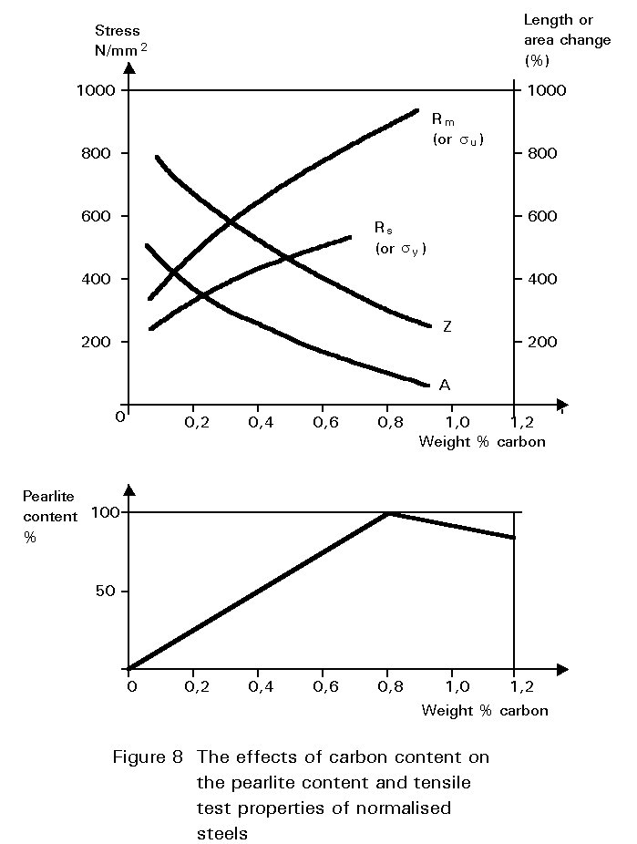
The dramatic effect of carbon content on toughness is shown in Figure 9. Increasing pearlite content decreases the upper shelf toughness and increases the ductile-brittle transition temperature.
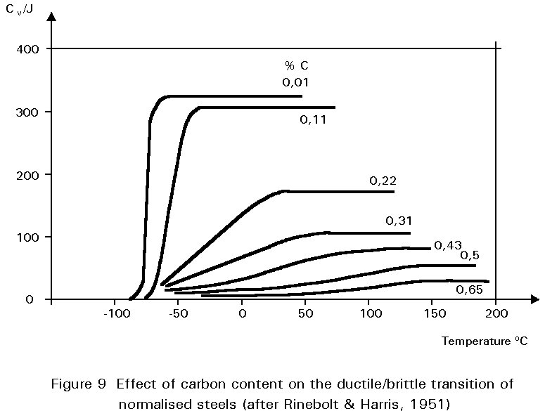
Figures 8 and 9 illustrate one of the difficulties in the choice of carbon content. Increasing the carbon content is beneficial in that it improves yield strength and ultimate tensile strength, but is undesirable in that it reduces ductility and toughness. A high carbon content may also cause problems during welding, see Section 4.3.
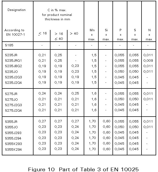
In European Norm 10025, Table 3, [3] the chemical composition for flat and long products is given. An extract is presented in Figure 10. The designation S235 JR, for example, indicates that the yield strength is at least 235 N/mm2. It is emphasised that the compositional values in the table are maximum values. Many steelmakers achieve much lower levels, resulting in better ductility, resistance against brittle fracture, and weldability.
The lowest carbon content that can be achieved easily on a large scale is about 0,04%. This content is characteristic of sheet or strip steels intended to be shaped by extensive cold deformation, as in deep drawing.
Carbon contents of more than 0,25% are used in the wider range of general engineering steels. These steels are usually put into service in the quenched and tempered state (see below) for a great multiplicity of purposes in mechanical engineering. High strength bolts for some structural applications would also be steels of this type.
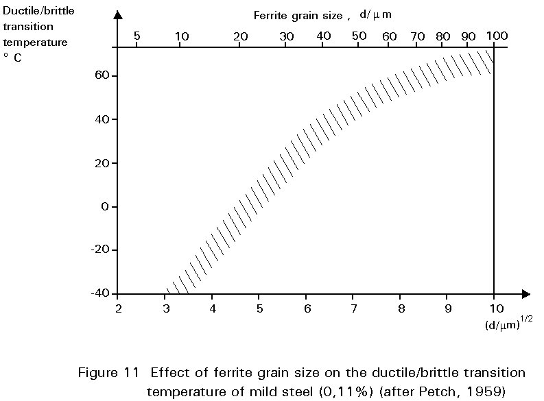
The mechanical properties of steel are affected by grain size. Slides 8 and 9 show microstructures of two samples of the same batch of mild steel which have been treated, by methods outlined in Section 4.2.3, to give different grain sizes. Reduction in grain size improves yield strength but also has a profound effect on the ductile/brittle transition temperature, see Figure 11. Thus, there are several benefits from the same microstructural charge. This is an unusual circumstance in metallurgy where adjustments to improve one property often mean a worsening of another and a compromise is necessary. An example of such compromise relates to carbon content, already discussed above.
Slide 8 : Microstructure of typical hot rolled structural steel containing 0,15% carbon and showing white ferrite grains and pearlite colonies. (x 200)
Slide 9 : Refined microstructure of controlled rolled structural steel containing 0,15% carbon (white ferrite grains and pearlite colonies. (x 200)
In Section 4.2.1 the transformations that can occur when steels are cooled slowly are described. To form ferrite and pearlite from austenite, the carbon atoms in the steel must change their positions. The diffusion processes which transport the atoms within the solid occur at rates which depend exponentially on temperature. The rate of cooling also affects these transformations.
If the cooling rate is increased the transformations occur faster. In addition, the diffusional processes cannot keep up with the falling temperature. Thus, a steel cooled very slowly in a furnace keeps close to the requirements of the phase diagram. But the same steel, removed from the furnace and allowed to cool in air, may undercool before completing its sequence of transformations. This more rapid cooling has two effects. First it tends to increase slightly the proportion of pearlite in the microstructure. Secondly it produces ferrite with a finer grain size and pearlite with finer lamellae. Both of these microstructural changes give higher yield strength and better ductility and toughness.
Furnace cooled steels are known as fully annealed steels. Air cooled steels are known as normalised steels.
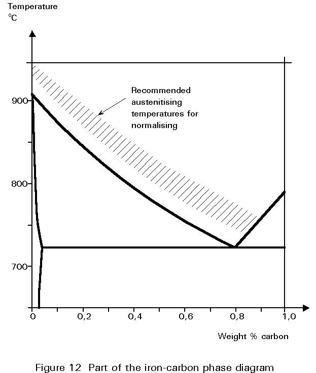
Grain size can also be affected by the temperature to which the steel is heated in the austenite range. The grains of austenite coarsen with time, the rate of coarsening increasing exponentially with temperature. The coarsening is important because the transformation to ferrite and pearlite on cooling starts at the grain boundaries in the austenite. If the new structures start growing from points which are further apart in a coarse grained austenite, the grain size of the resulting ferrite is itself coarser. Thus, steels should not be overheated when austenitising before normalising.
The temperature to which the steel is heated before cooling in air is usually referred to as the normalising temperature. The requirements of the last paragraph mean that this temperature should be as low as possible, as long as the structure is single phase austenite. A glance at the phase diagram of Figure 5 shows that the normalising temperature decreases as the carbon content increases from zero to 0,8%. It should lie in the hatched band shown in Figure 12.
Structural steel sections are produced by hot rolling ingots or continuously cast strand into the required forms. The rolling processes have important effects on the development of the microstructure in the materials.
The early stages of rolling are carried out at temperatures well within the austenite range, where the steel is soft and easily deformed. The deformation suffered by the material breaks up the coarse as-cast grain structure but, at these high temperatures, the atoms within the material can diffuse rapidly which allows the deformed grains to recrystallise and reform the equiaxial polycrystalline structure of the austenite.
Heavy deformation at low temperatures in the austenite range gives finer recrystallised grains. If the rolling is finished at a temperature just above the ferrite + austenite region of the equilibrium diagram and the section is allowed to cool in air, an ordinary normalised microstructure having moderately fine-grained ferrite results. Modern controlled rolling techniques aim to do this, or even to roll at still lower temperatures to give still finer grains.
If the temperature falls so that the rolling is finished in the ferrite + austenite range, the mixture of ferrite and austenite grains is elongated along the rolling direction and a layer-like structure is developed. If now, the section is air-cooled, the residual austenite decomposes into fine-grained ferrite and pearlite, with the later being present as long, cigar shaped, bands in the material, as in Slide 10. Structural steels are not harmed by microstructures of this sort.
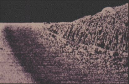
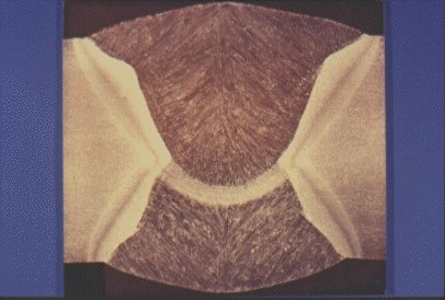
Slide 10 : Microsection through a fillet weld on structural steel showing three distinct regions: the coarse grained cast structure of the weld deposit, the heat affected zone, and the unaffected microctructure of the parent steel. (x 200)
If the finish rolling temperature drops further, to below 723°C, the equilibrium diagram shows that the structure should be a mixture of ferrite and pearlite. Rolling in this range is usually restricted to low carbon steels containing less than 0,15%C because the presence of pearlite makes rolling difficult.
If the temperature is above about 650°C, the ferrite grains recrystallise as they are deformed, as was the case with austenite. The carbide laths (Fe3C) in the pearlite become broken and give rise to strings of small carbide particles extending in the direction of rolling, see Slide 11. The ferrite from the pearlite becomes indistinguishable from the rest of the ferrite.
Slide 11 : Macrosection through a butt weld on hot rolled steel plate, typical of line pipe weld.
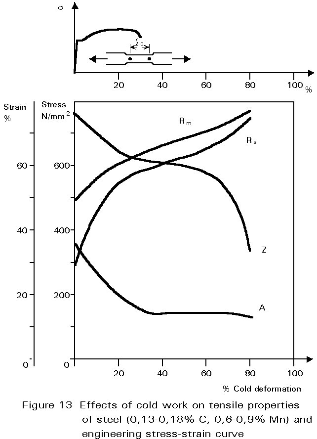
If rolling is done at ambient temperature, the pearlite is broken up in the same way, but the ferrite can not recrystallise. It work-hardens, i.e. the yield and ultimate tensile strength of the steel increase, and the ductility decreases, see Figure 13. As cold rolling continues, the force required to continue deformation increases because of the increasing yield strength. Furthermore, the steel becomes less ductile and may begin to split. The amount of cold rolling that can be done is therefore very much smaller than that which can be achieved when the steel is hot.
Of course, cold working need not be applied by rolling. Any way of deforming the material causes work hardening. For example, high strength steel wire is made by cold-drawing, imparting large deformations. In another example, one type of reinforcing bar is made by twisting square section bar into a helical form. The cold-deformation produced in this way is not large but causes significant work hardening.
To restore the ductility and at the same time reduce the work hardened state of the material, it is necessary to reform the isotropic, polycrystalline structure of the ferrite. Re-heating to temperatures between about 650°C and 723°C allows the ferrite to recrystallise. The carbide particles are unaffected by this treatment.
Thus, there is another technique for controlling the grain size of steel. The greater the amount of deformation before the recrystallisation treatment and the lower the temperature of the treatment, the finer is the final grain size. Because this type of treatment does not involve the formation and decomposition of austenite, it is known as sub-critical annealing. The resulting microstructure has good ductility and deep drawing characteristics. Sheet steels of low carbon content (< 0,1%C) are usually supplied in this condition. Objects such as motor car body panels are formed from such steels by cold pressing.
If the material is heated into the austenite range, subsequent cooling reforms the normalised microstructure.
Normalising causes steels to undercool below the requirements of the phase diagram before the austenite transforms into fine ferrite and pearlite. Still further increases in cooling rate give further undercooling and still finer microstructures.
Very rapid cooling by quenching into cold water, causes the formation of ferrite and pearlite to be suspended. The internal diffusion-controlled rearrangement of atoms needed to form those products cannot occur sufficiently rapidly. Instead, new products are formed by microstructural shear transformations at lower temperatures. Very fast cooling gives martensite: its microstructure is shown in Slide 12. When martensite forms, there is no time for the formation of cementite and the austenite transforms to a highly distorted form of ferrite which is super saturated with dissolved carbon. The combination of the lattice distortion and the severe work hardening resulting from the shear deformation processes necessary to achieve the transformation cause martensite to be extremely strong but very brittle.
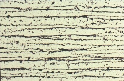
Slide 12 : Longitudinal section of hot rolled structural steel showing dark bands of pearlite in a ferrite matrix. (x 200)
Less rapid cooling can give a product called bainite,. This is similar to tempered martensite where much of the carbon has come out of solution and formed fine needles of cementite which reinforce the ferrite.
Civil engineering structures are not heat-treated by heating to, say, 900°C and quenching into water. However, there is one important circumstance which can produce martensite in localised parts of the structure, and that is welding. The weld zone is raised to the melting temperature of the steel and the immediately adjacent solid metal is heated to temperatures well within the austenite range. When the heat source is removed, the whole region cools at rates determined mainly be thermal conduction into the surrounding mass of cold metal. These rates of cooling can be very large, exceeding 1000°C per second in some cases and can produce transformation structures such as martensite and bainite. The properties of rapidly cooled steels and the influence of carbon content on the nature of the transformation product - ferrite and pearlite, or bainite, or martensite - are discussed below.
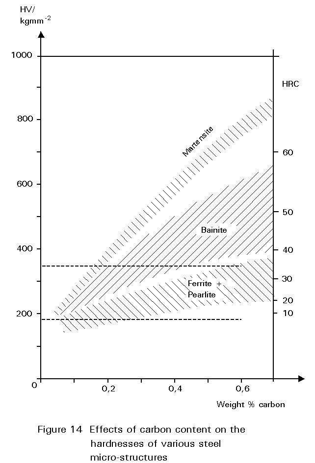
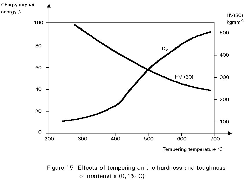
Figure 14 shows the hardness of martensite as a function of its carbon content. Reheating martensite to temperatures up to about 600°C causes cementite to precipitate which causes the steel to soften and become much tougher. This reheating is known as tempering. The extent of these changes increases as the reheating temperature increases, as shown in Figure 15. Tempering at 600°C produces an extremely tough material. What is more, its ductile-brittle transition temperature is lower than for the same steel in the normalised condition. Bainite has properties similar to those of tempered martensite.
The process of quenching and tempering, when allied to changes of steel composition, can produce a bewilderingly wide range of properties. Steels heat-treated in this way are used for a multiplicity of general engineering purposes which demand hardness, wear resistance, strength and toughness. Once again, compromises must be struck between these desirable properties but generally quenched and tempered steels exhibit optimum combinations of strength and toughness. For structural purposes quenched and tempered plate is used in large storage tanks, hoppers, earthmoving equipment, etc.
Martensite produced in a weld heat-affected zone as a result of single pass welding would be in its hard and brittle untempered condition. Furthermore, the formation of martensite from austenite is accompanied by a volume expansion of approximately 0,4%. This expansion, together with the uneven thermal contractions taking place as a result of uneven cooling, can produce local stresses of sufficient magnitude to crack the martensite. Because this type of cracking occurs after the HAZ has cooled, it is referred to as cold cracking. The cracking problem can be further aggravated if the weld has picked up hydrogen. Sources of hydrogen during welding might include moisture from the atmosphere or damp welding electrodes. Hydrogen dissolved in the weld metal diffuses to the hard HAZ where it initiates cracks at sites of stress concentration. This diffusion can lead to cracking which occurs some time, even days, after the welding is completed. Hard HAZs of low ductility are less able to cope with this problem than are softer and more ductile materials. This type of cracking is called delayed cracking or hydrogen cracking.
Avoidance of cold cracking and hydrogen cracking requires that the material should not be overhardened. As a rule of thumb, as-welded hardnesses of less than about HV = 350 are considered to be acceptable. In modern fine grain low carbon steels the "allowable" hardness may be increased to HV = 400 or even HV = 450.
The danger of hydrogen cracking may also be present in high strength quenched and tempered steels, e.g. 10.9 bolts (Re ³ 900 N/mm2 and Rm ³ 1000 N/mm2). When such bolts are electroplated with zinc or cadmium, hydrogen may be picked up from the plating bath. Usually cracking does not occur until sometime after tightening bolts when the hydrogen has diffused to the sites of stress concentration at the thread roots.
Martensite forms because ferrite and pearlite did not! If follows that metallurgical factors which promote the formation of ferrite and pearlite inhibit the production of martensite. The ability of a steel to form martensite rather than ferrite and cementite is called hardenability. Note that this term does not refer to the absolute value of hardness obtained, but to the ease of formation of martensite.
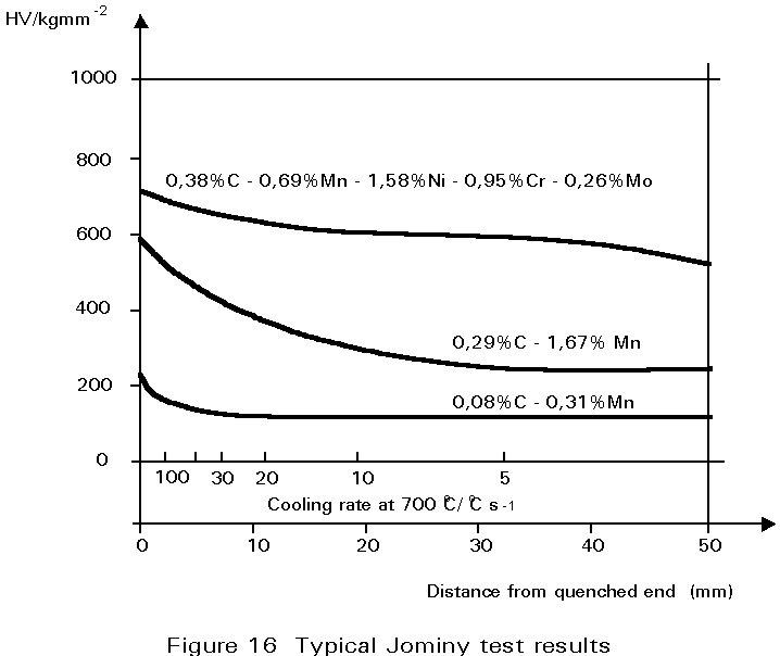
The most convenient method of assessing hardenability is the so called Jominy end quench. A rod-shaped sample is austenitised and then quenched by spraying water onto one end face such that different cooling rates are produced along the length of the bar. Thereafter, a flat is ground along its length and the hardness measured as a function of distance from the quenched end.
Some typical results are shown in Figure 16 for three different steels. For a carbon steel containing 0,08%C and 0,3%Mn, cooling rates at 700°C of greater than about 50°C s-1 are necessary to form martensite. On the other hand in the 0,29%C, 1,7%Mn steel, martensite forms at much slower cooling rates. It is mainly the increased carbon content that causes this difference. In the alloy steel illustrated, martensite is formed even at very slow cooling rates.
The significance of these curves depends very much on what is being produced. If it is a thick-section gear wheel, the alloy steel would be ideal. It could be cooled gently and still produce martensite, the gentle cooling being an advantage because it would reduce stresses arising from differential contraction rates, and hence reduce the possibility of quench cracking. Thereafter, it could be tempered to achieve the desired combination of strength and toughness. On the other hand, for a welded joint, the plain carbon steel would be preferable in which it is difficult to form martensite and the hardness of any martensite produced would be relatively low.
Welding presents particular problems for the metallurgist. Slide 13 shows a micro section through a typical structural weld. The micro structures range from the coarse grained cast structure of the weld deposit, to the heat affected zone (HAZ) and to the unaffected microstructure of the parent metal. Both the deposited weld metal and the HAZ must have adequate strength and toughness after welding.
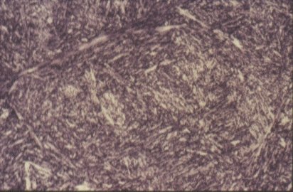
Slide 13 : Microstructure of martensite (x 500)
For welding, a steel of low hardenability is therefore required. Hardenability is affected by steel composition, including not only carbon content but other alloying elements as well. To take all of these factors into account, the concept of the carbon equivalent value is used. There are a number of ways of calculating carbon equivalents for use in different circumstances. In the context of welding:
C.E. = ![]()
If the CE is lower than about 0,4%, the steel can be welded with little or no trouble from martensite and HAZ hydrogen cracking. As indicated before, the cooling rate is also an important factor, which means that during welding, thick plates are more susceptible to hydrogen cracking than thin plates. To reduce susceptibility to martensite formation, the cooling rate (between 800°C and 500°C) can be reduced by preheating the plates before welding.
One tonne of steel, a cube with sides of about 0,5m, contains between 1012 and 1015 inclusions which can occupy up to about 1% of the volume. The total content is largely determined by the origins of the ores, coke and other materials used to extract the metal in the first place, and by the details of steelmaking practice.
The principal impurities which worry steelmakers are phosphorus and sulphur. If not at very low concentrations, these impurities form particles of phosphide and sulphide which are harmful to the toughness of the steel. Typically, less than 0,05% of each of these elements is demanded. Low phosphorus contents are relatively easily attained during the refining of the pig iron into steel, but sulphur is more difficult to remove. It is controlled by careful choice of raw materials and, in modern steelmaking, by extra processing steps to remove it.
Manganese is always added to steels. It has several functions but the important one in this context is that it combines with the sulphur to form manganese sulphide (MnS). If the manganese were not present, iron sulphide would form which is much more harmful than MnS.
Some of the inclusions are too small to be seen with optical microscopes and must be detected by more elaborate methods. Among this group, which are mainly equiaxial in shape, are nitrides of aluminium and titanium which are deliberately introduced in order to inhibit the processes which lead to coarsening of grain size.
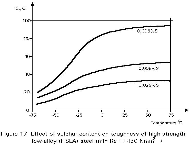
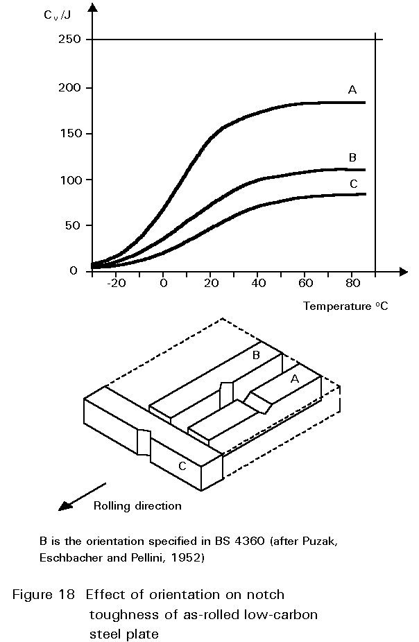
Other inclusions, large enough to be seen readily with the optical microscope, include entrained particles of slag, deoxidation products and manganese sulphide. At hot rolling temperatures, these inclusions are plastic and are elongated in the rolling direction. The result is shown in Figure 1. The properties of steels containing such inclusions reflect both the volume of the inclusions and the anisotropy of their shapes, see Figures 17 and 18.
In recent years, a number of practices have been introduced which aim to reduce the inclusion content in the molten steel before it is cast into ingots. Sulphur contents of 0,01% or less are now regularly produced. These processes produce what have become known as 'clean steels'. The expression is relative. Clean steels still contain many inclusions, but are significantly tougher than ordinary steels. Inclusion shape control is also practised in better quality steels. Additions of calcium or cerium and other rare earth elements to the refined molten steel combine with the sulphur in preference to the manganese. Sulphides of these elements appear in the final microstructure as equiaxial particles and are not so deleterious to the through-thickness ductility of the material as elongated MnS inclusions. Steels treated in these ways are used in applications where toughness is of paramount importance and where the extra cost can be justified. Examples include high integrity pressure vessels, oil and gas pipelines and the main legs of offshore platforms. The introduction of continuous casting has also improved the quality of conventional structural steels.
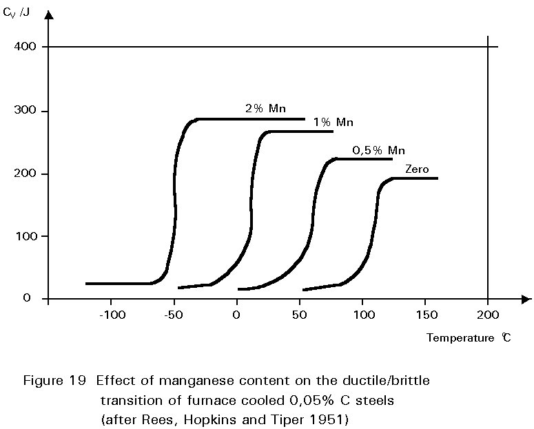
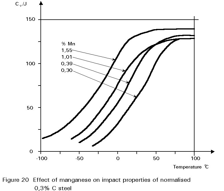
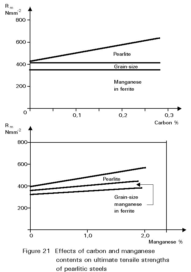
It has been noted earlier that the residual sulphur impurity in steel is less harmful when formed into particles of MnS rather than iron sulphide. The presence of small amounts of manganese in the steel confers several other benefits. In normalised steels, it tends to increase the amount of undercooling before the start of the formation of ferrite and pearlite. This gives finer grained ferrite and more finely divided pearlite. Both of these changes improve strength and reduce the ductile/brittle transition temperature. The dissolution of the manganese atoms in the ferrite crystals also improves the strength of the ferrite. These effects on properties are summarised in Figures 19 - 21.
If the manganese content is increased too much, its effect ceases to be beneficial and can become harmful because it increases hardenability, i.e. promotes martensite formation. It is for this reason that a maximum manganese content is specified: For S355 in Table 3 of EN 10025 this maximum is 1,7% by weight, see Figure 16. A convention has also grown that distinguishes between plain carbon steels, i.e. steels containing < 1%Mn, and carbon manganese steels i.e. >1%Mn.
[1] Eurocode 3: 'Design of Steel Structures' ENV 1993-1-1: Part 1.1: General Rules and Rules for Buildings, CEN, 1992.
[2] Rollason, E. C., 'Metallurgy for Engineers', 4th Edition, Arnold, 1973.
[3] Euronorm 10025