ESDEP WG 9
THIN-WALLED CONSTRUCTION
To introduce cold-formed members, and to discuss their manufacture, applications and design.
Lecture 6.2: General Criteria for Elastic Stability
Lectures 6.6: Buckling of Real Structural Elements
Lecture 8.1: Introduction to Plate Behaviour and Design
Lecture 2.4: Steel Grades and Qualities
Lecture 4A.3: Practical Corrosion Protection for Buildings
Lecture 14.1.1: Single-Storey Buildings: Introduction and Primary Structure
This lecture introduces cold-formed sections and members; it discusses methods of manufacture and applications and shows how these sections have certain advantages over more conventional steelwork. The design methods generally used are explained and advice is given on practical considerations.
Formerly the use of cold-formed thin-walled steel sections was mainly confined to products where weight saving was of prime importance, e.g. in the aircraft, railway and motor industries. Simple types of cold-formed profiles (mainly similar to hot-rolled shapes), as well as profiled sheeting, have also been used as non-structural elements in building for about one hundred years.
Systematic research work, carried out over the past four decades, as well as improved manufacturing technology, protection against corrosion, increased material strength and the availability of codes of practice for design, have led to wider use of cold-formed sections within the building industry. In many countries cold-formed steel construction is the fastest growing branch of the structural steel market.
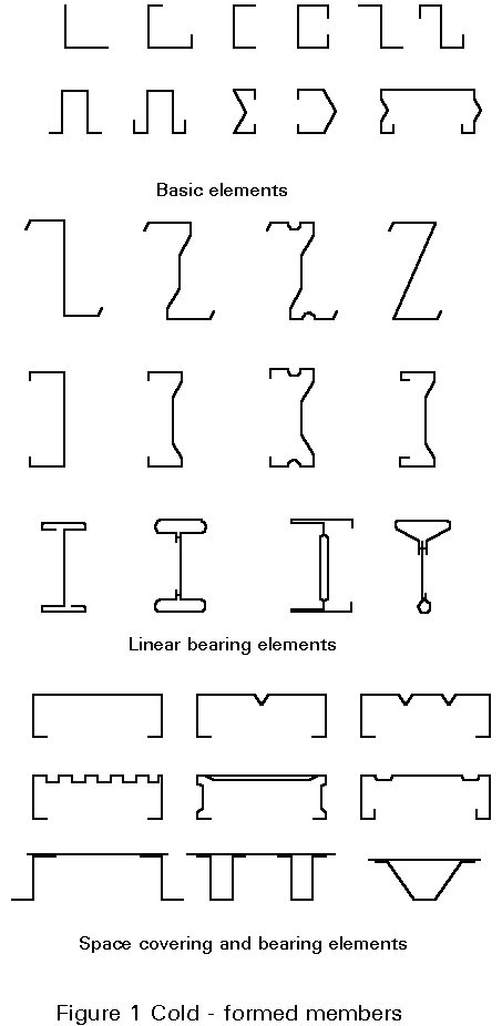
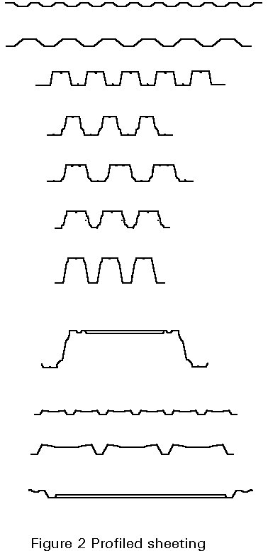
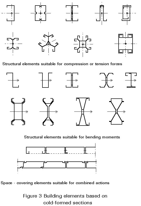
Cold-formed sections are prismatic elements, of constant sheet thickness, formed by a sequence of plane sub-elements and folds in order to perform specific load bearing functions for members and also sometimes a space-covering function (see Figures 1-3).
A characteristic feature of cold-formed sections is that slender parts in compression are stiffened by folding (intermediate and edge stiffeners), which delays or prevents premature buckling of the compressed zones. This phenomenon is discussed in Section 2.
The types of products available for use in building structures are:
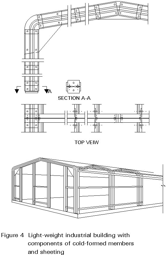
Cold-formed thin-walled building elements are, therefore, mainly used in low-rise and light industrial buildings with small spans, where combination of cold-formed sections and profiled sheeting can be utilised to the best advantage. Stressed skin design of profiled sheeting can also have applications in the more interesting field of space structures such as folded plates or hyperbolic paraboloid shells.
The use of cold-formed structural members offers many advantages over construction using more standard steel elements;
These advantages can, therefore, be generally classified as weight-saving, by optimization of the products with respect to the load-bearing function and constructional demands; and functional performance in terms of space-covering ability.
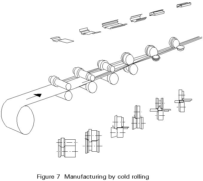
Cold-formed sections can be manufactured either by folding (Figure 5), press braking (Figure 6), or cold rolling (Figure 7).
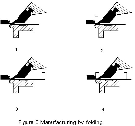
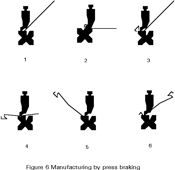
For small batches of building elements with lengths £ 6m (in exceptional cases £ 12m), it is normally advantageous to use hydraulic folding or press-braking machines. The effort required to form the shape depends on the sheet thickness, the ductility of the material and the shape of the section, which is limited by the strip width.
These manufacturing methods allow the sections to be shaped for optimum load- bearing resistance, intended purpose and further product processing.
The type of steel used should be suitable for cold-forming and, if required, for galvanising. For cold-formed sections and sheeting it is preferable to use cold-rolled continuously galvanized steel with yield stresses in the range of 280-320-350N/mm2, and with a total elongation of at least 10% for a 12,5mm wide strip, referred to a gauge length lo =80mm, and a ratio of ultimate tensile strength to yield stress of at least 1,1.
Under normal conditions, zinc protection Z275 (275g/m2) is sufficient; in more corrosive environments, improved protection using suitable coating systems may be necessary. Continuously applied zinc protective coating systems are generally limited in core thickness to about 3,5mm. For increased material thickness, hot-dip galvanizing and site- or shop-applied top coats may be used.
Cold-forming techniques allow the geometrical properties of a shape to be readily varied. It is possible, therefore, to influence the load-bearing behaviour of the element with respect to strength, stiffness and failure modes by, for example, the introduction of intermediate stiffeners or by ensuring adequate width-to-thickness ratios in adjacent flat parts of the section.
As cold forming of the steel sheet involves work hardening effects, the yield stress, the ultimate strength and the ductility are all locally influenced by an amount which depends on the bending radius, the thickness of the sheet, the type of steel and the forming process. The average yield stress of the section then depends on the number of corners and the width of the flat elements. The effect of cold forming on the yield stress is illustrated in Figure 8.
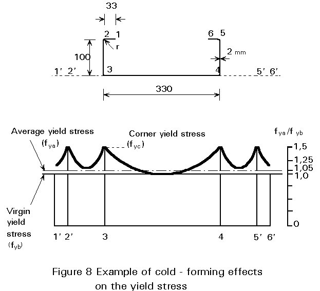
The average yield stress can be estimated by approximate expressions given in the appropriate codes. In the example, the average yield stress ratio fya/fyb» 1,05 and the corner yield stress ratio fyc/fyb» 1,4.
During the cold-forming process varying stretching forces can also induce residual stresses, which can significantly change the load-bearing resistance of a section. Favourable effects can be observed if residual stresses are induced in parts of the section which act in compression and, at the same time, are susceptible to local buckling.
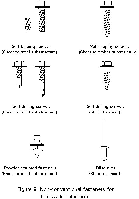
The development of lightweight construction requires the availability of adequate fastening techniques; suitable fasteners are bolts with nuts, blind rivets, self-tapping screws, self-drilling screws and powder actuated fasteners (Figure 9); industrialized production spot welding and adhesives may also be used. In order to use fasteners in building construction, it is necessary to be familiar with the behaviour of the connections and to lay down design criteria for serviceability and stability. Comprehensive experimental and theoretical investigations form the basis of the analytical evaluation of the load-bearing behaviour of the fasteners under static and dynamic loading. Figure 10 shows fields of application and the appropriate failure modes.
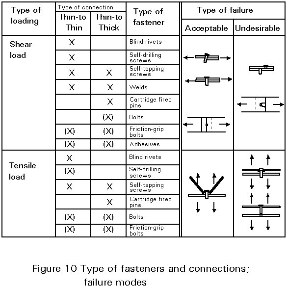
Generally, failure modes causing sudden failure of connections should be avoided. Local over-stressing is indicated by large deformations and should be reduced by load transmission to adjacent fasteners.
Extensive research and product development in the past has led to national design specifications for cold-formed sections and structures in many countries. European Recommendations for the design of cold-formed sections have been developed by the European Convention for Constructional Steelwork [1,2], and form the basis for Part 1.3 of Eurocode 3 "Cold-formed thin-gauge members and sheeting" [3].
Compared with conventional steel members, thin-walled structural elements are characterised by:
As a consequence, a number of factors must be considered when designing these elements:
Under increasing load, thin-walled structural elements are generally subject to varying non-linear distributions of stress and strain over the cross-section, often in conjunction with substantial out-of-plane deflections. There is also the possibility of different failure modes, particularly for sections with flat parts in compression which are unstiffened, i.e. elastically restrained along one edge only.
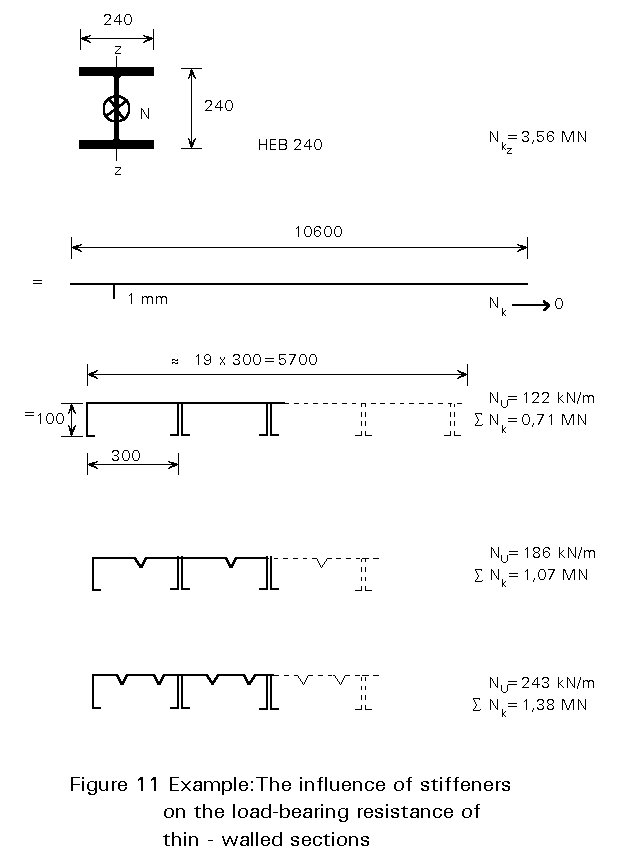
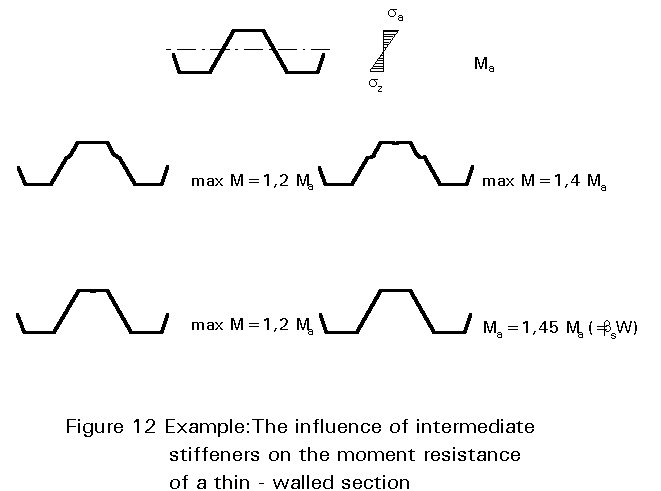
The influence of stiffeners on the load-bearing resistance is illustrated in Figure 11, where the mass and nominal force at failure of a hot-rolled profiled HEB240 is compared with different shapes of thin-walled elements. In addition, this example shows the advantage of the space-covering function of thin-walled elements. Another example is given in Figure 12, where the increase in moment resistance due to intermediate flange and web stiffeners is shown.
It is evident from the above discussion that an accurate analysis of the mode of action is usually extremely complicated, especially when imperfections and plasticity have to be taken into consideration. For practical design there is a need for simplified analytical models which allow an approximate but conservative estimate of the failure load and the behaviour of the structure under service load to be made.
As illustrated above, the effect of local buckling in the compression elements of a section often determines the behaviour and load-bearing resistance. The theoretical solution to this problem, taking into account the post-buckling strength, is not practical for design purposes, for which the effective width design model has been developed.
It is evident from the stress distribution of a simply supported plate strip under normal forces (see Figure 13a) that in the post-buckling range the stresses are concentrated along the plate supports. Thus, the ultimate load can be determined from a uniform stress distribution within an effective width bef, which depends on the critical buckling stress (scr=bifurcation stress) and the yield stress (fy) of the plate material. The expression for bef, given by Von Karman, has been subsequently modified by Winter with provision for unintended geometrical imperfections (see Figure 13b).
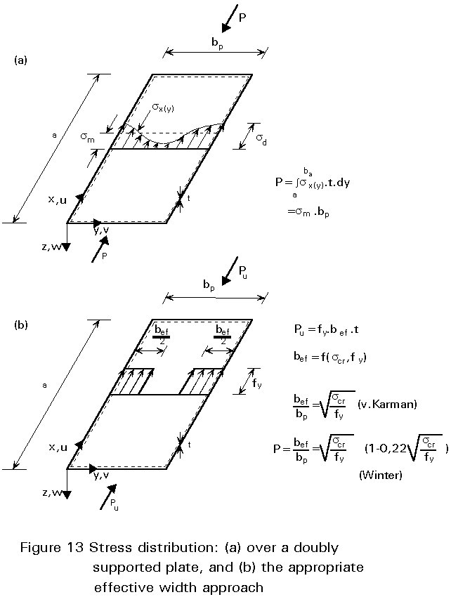
The "Winter-Formula"
r = 
implies that bef=0,78 bp, when scr=fy.
Substituting scr, the relative slenderness
![]() p
is given by:
p
is given by:
![]() p
= (1,052/Öks)(bp/t)(Öfy/E)
p
= (1,052/Öks)(bp/t)(Öfy/E)
and
r = (1/![]() p)(1
- 0,22/
p)(1
- 0,22/![]() p)
p)
i.e. that r = 1,0 if ![]() p
£ 0,673.
p
£ 0,673.
If the buckling factor ks for the bifurcation stress is known, the effective width bef can be calculated; for example, bef=bp for a doubly supported plate element under constant normal stress with ks =4, if bp/t £ 1,33 E/fy; or for a singly supported plate element with ks =0,43 if bp/t £ 0,42 E/fy. Assuming a yield stress fy=320N/mm2, the elements are fully effective if bp/t £ 34 or bp/t £ 11 respectively.
Where appropriate these reduced effective widths should be taken into account by using the effective values of the section properties, i.e. the effective area (Aef), section modulus (Wef), and moment of inertia (Ief). Appropriate ks values are given in [1].
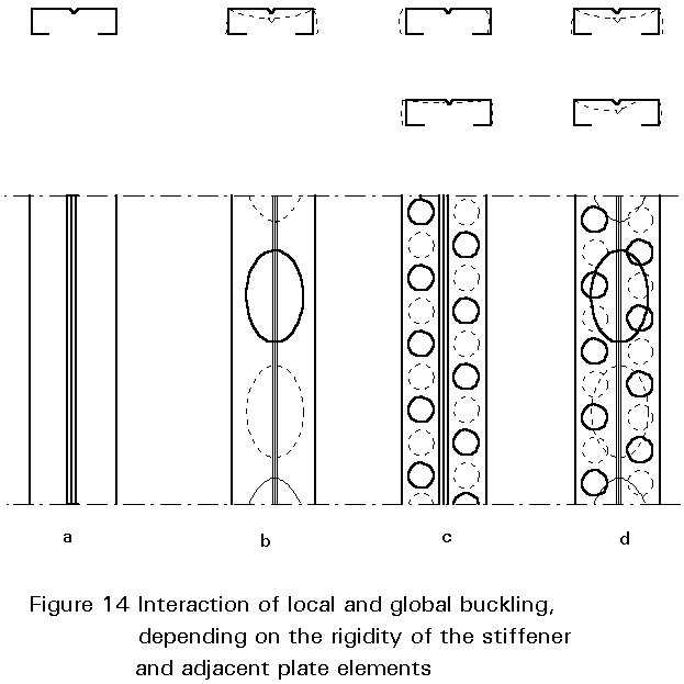
Elements of a section are either doubly supported (flanges or webs of trapezoidal sheeting) or singly supported (flanges of U- or L-shaped profiles). Doubly supported elements are much stronger, especially when they also have low b/t ratios; this can be achieved by longitudinal edge stiffeners, (lips, bends folds) and/or by intermediate V, U or trapezoidal shaped stiffeners (see Figures 1, 2). These stiffeners, located in the compression zone, are subjected to normal forces and, working as beam columns on elastic foundations, are prone to buckling. This behaviour gives the basis for a simplified design model where the stiffener and adjacent parts of the flat elements are treated as beams on elastic foundation, with a spring stiffness dependent on the boundary conditions of the element.
The buckling mode and load depend on the effective area and stiffness of the stiffener. If the stiffener has an adequate stiffness, it may be treated as a rigid support for the adjacent flat element; codes of practice gives approximate criteria for assessing this. Depending on the buckling load of the stiffener, an interaction of local and global buckling may occur, as illustrated in Figure 14.
The first step when analyzing the load-bearing behaviour and estimating the failure load of a cold-formed member is to evaluate the effective width of the compression elements of the section, based on the appropriate stress distribution over the cross-section; the next step is to calculate the geometric properties of the effective section, taking into account the shift of the neutral axis caused by disregarding the ineffective parts of the section. Thereafter the design procedure is the same as for thick-walled sections. In general, the resistance of a thin-walled effective cross-section is limited by the design yield stress at any part of the section, based on an elastic analysis. Deviations from this rule are only permitted in special cases.
In the following, only basic design rules are used in order to explain the design procedure; the interaction of different effects, causing biaxial stress distributions, follows the same principles as for hot-rolled members.
In general terms, the design resistance is based on the value fy/gM, where gM is a partial safety factor for resistance (normally gM=1,1).
If the member does not buckle the moment resistance is given by:
RM = Weff.fy/gM
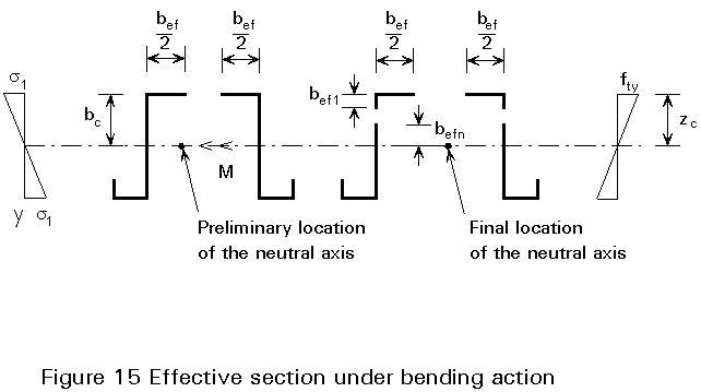
where Weff is the section modulus of the effective cross-section. In order to avoid an iterative procedure, the effective portions of the web may be based on c =s2/s1, obtained by assuming the compression flange to be reduced, but the web being fully effective (see Figure 15).
When yielding first occurs on the tension side, the plastic reserves of the tension zone can be utilized until the compression stress reaches fy. This will normally lead to iterative calculations.
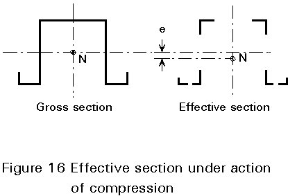
If the same section is affected by a normal force acting at the centre of gravity of the cross-section, the effective section has to be determined with respect to compressive stresses in each element. As illustrated in Figure 16, it may happen that the centre of gravity of the effective section moves, causing an additional bending moment (M=Ne). This implies that cross-sections, where the effective neutral axis has shifted, have to be checked for compression and bending.
Web buckling can be caused by compressive bending stresses or by shear stresses above the critical buckling strength. In both cases, the buckling strength depends on the web slenderness (sw/t). For a yield stress of about fy=320N/mm2, webs are prone to buckling if sw/t>80 for pure bending and sw/t>60 for pure shear. However, buckling does not necessarily imply a limit state for the structure, if post-critical equilibrium can be relied on (Figure 17).
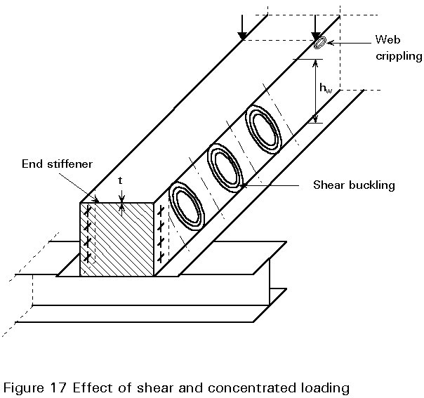
Crippling is a phenomenon associated with local loading of high intensity perpendicular to the plane of the web. It is most evident in the case of concentrated loading (Figure 17) or at intermediate supports of continuous beams. It is often more severe than web buckling, since crippling reduces the effective depth of a section and there is no post-critical strength. Depending on the webs' eccentricity relative to the load direction, and on the category of loads (see below), various values for web crippling resistance can be expected (Figure 18).
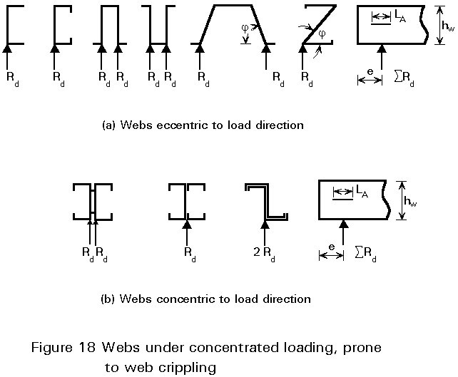
First category loads include end supports of beams, loads near the ends of a cantilever, and loads applied so close to a support that the distance from the support to the nearest edge of the load, measured parallel to the beam axis, is less than 1,5sw.
Second category loads include intermediate supports and loads situated more than 1,5sw from a support or an end of a cantilever.
It should be noted that expressions given in the codes are semi-empirical.
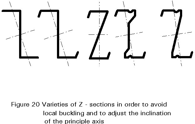
Unbraced members in flexure are generally susceptible to lateral-torsional buckling; this type of failure is more likely if the section is subjected to torsion due to the inclination of the main axis relative to the load direction, or if the shear centre of the section is not on the loading axis.
In order to minimise these effects, varieties of Z- and C-sections have been developed (see Figures 19 and 20).
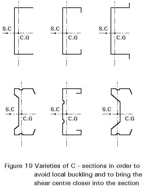
The susceptibility of thin-walled open sections to twisting and lateral-torsional buckling can effectively be neutralized by restraints provided by adjacent building elements, for example, metal sheeting connected to the sections using self drilling or self tapping screws.
In the case where Z-purlins are used for roof structures, the lower flange is normally free to rotate whereas the upper flange is attached to the sheeting. The in-plane stiffness of the sheeting prevents a lateral displacement of the upper flange and the distance between the fasteners and the edges of the section provides the lever arm for torsional restraint. The rotational spring stiffness Cu [Nm/rad] depends on the bending stiffness of the sheeting (Cum), the distortion of the section (Cup) and the stiffness of the connection between the sheeting and the purlin (CuA); the last value must be estimated by tests.
From 1/Cu = 1/Cum + 1/Cup + 1/CuA
the effective value of Cu can be derived.
The exact analytical solution of the problem of lateral buckling of continuous beams is too complicated for practical use; however, the beam-on-elastic-foundation model can help to solve the problem.
It is obvious that local buckling influences the load-bearing resistance of a section subjected to axial loading. Using the effective width method, the reduced (effective) area Aef has to be taken into account when calculating the slenderness of the column
(lp/ief).(Aef/Ag)1/2 and when determining the design resistance Nd=k Aef fy/gM. The buckling factor k is taken from the relevant European buckling curves (a-d) for the appropriate value of ![]() . The classification of section types shows that members without end stiffeners should be avoided since the load-bearing resistance is relatively low (see also Lecture 9.2).
. The classification of section types shows that members without end stiffeners should be avoided since the load-bearing resistance is relatively low (see also Lecture 9.2).
As cold-formed sections are characterised by relatively low sheet thicknesses and/or high width thickness ratios account must be taken of:
Members and structures should be designed so that:
If thin-walled members are connected to each other by mechanical fasteners, the rigidity of the joints is influenced by slip and by local buckling effects in front of the fasteners - the latter may occur if bolts are used in order to transmit relatively high forces; another possible problem is where the rigidity is reduced by large reductions in effective areas within the joint. The flexibility of the joint may influence the distribution and redistribution of bending moments and shear within the structure, and also the calculation of the load-bearing resistance. These effects must be properly investigated - by testing if necessary.
[1] European Convention for Constructional Steelwork: "European Recommendations for the Design of Light Gauge Steel Members", Publication 49, ECCS, 1987.
[2] European Convention for Constructional Steelwork: "European Recommendations for the Design of Profiled Sheeting", Publication 40, ECCS, 1983.
[3] Eurocode 3, Part 1.3: "Cold-formed Thin-gauge Members and Sheeting" CEN (in preparation).