ESDEP WG 14
STRUCTURAL SYSTEMS: BUILDINGS
To present the factors which are taken into account in the analysis of multi-storey buildings, and the methods which can be adopted.
Lecture 1B.3: Background to Loadings
Lectures 1B.7: Introduction to Design of Multi-Storey Buildings
Lectures 5: Computer Aided Design and Manufacture
Lecture 14.7: Anatomy of Multi-Storey Buildings
Lecture 14.10: Simple Braced Non-Sway Multi-Storey Buildings
Lecture 14.13: Design of Multi-Storey Frames with Partial Strength & Semi-Rigid Connections
Lecture 14.15: Tall Building Design
Methods of analysing the elements of structure described in Lecture 14.7 are presented.
The following aspects are considered:
Lecture 14.7 described the assembly of the structural elements forming the anatomy of multi-storey buildings. This lecture examines the procedures which should be adopted to conduct an analysis of the structure. It should be noted that specific methods of analysis for certain types of frames (e.g. rigid jointed, wind-moment, braced and partial strength) are, for clarity, presented in the appropriate subsequent lectures. The objective of this particular lecture is therefore to introduce the general philosophy of frame analysis and to identify those considerations which are common to all frame types.
The objectives of analysis are:
In order determine whether the structure is satisfactory, the structural response is compared with the appropriate codified limits, e.g. member stresses, local and overall deflection response, stability criteria, etc.
Clearly it is important that the model assumed in the analysis is indeed representative of the way in which the proposed structure would behave. As a result, it is important that prior to conducting an analysis, consideration is given to the following:
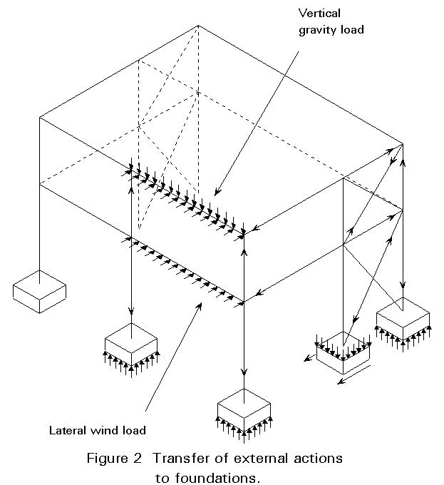
The following categories of loading are considered for the analysis of multi-storey buildings:
These actions typically comprise the following:
Information on the characteristic load for proprietary products can be obtained from manufacturer's literature.
Minimum imposed loading is based on the usage of the building being considered, and specified in local regulations. Buildings are often designed for imposed loads specified in excess of these minima, to increase the flexibility of future usage. Items to consider are:
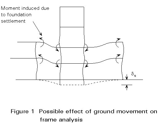
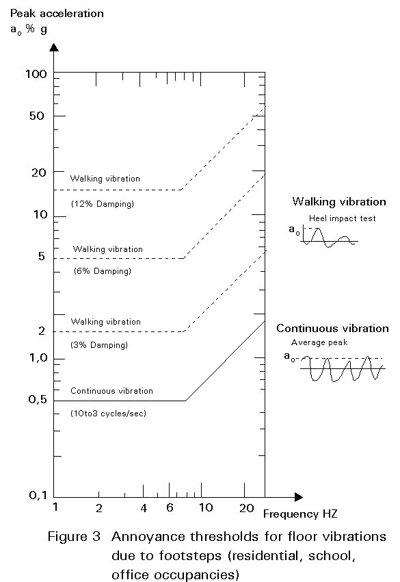
Usually only static analysis is required for imposed load, but dynamic analysis may be necessary to assess the effects of:
Figure 3 presents generally accepted limits (annoyance thresholds) for vibrations induced by walking.
The magnitude of the design wind loading to be applied to a building depends on the location and local topography of the site. The following terms are used to describe the different types of wind loading:
Cross-wind effects may also be present:
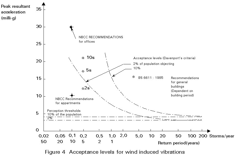
For low and medium rise multi-storey buildings, complex wind analysis is usually unnecessary, and equivalent static loads defined in local regulations or Eurocode 1 (when available) may be used. Cross-wind effects are not normally significant for ultimate limit state analysis, but can have an important influence on comfort. Figure 4 presents some acceptance levels for wind induced vibrations.
Seismic action need normally not be considered in northern Europe, but is the dominating action in southern Europe. It is a function of:
Buildings subjected to seismic forces should be designed not only for strength but also for ductility. Details for the seismic resistant design are given in Lectures 17.
Depending on the size and layout of the structure, thermal strains due to change in temperature can be significant. For example, if a long building has stiff bracing frames at each end, differential thermal strains will be generated between the superstructure and the foundations and large internal forces will be generated in beams and bracings (Figure 5a). To avoid this inconvenience, the location of bracings in the middle of the structure allows for free expansion of members without any restraint (Figure 5b), so no additional internal forces arise.
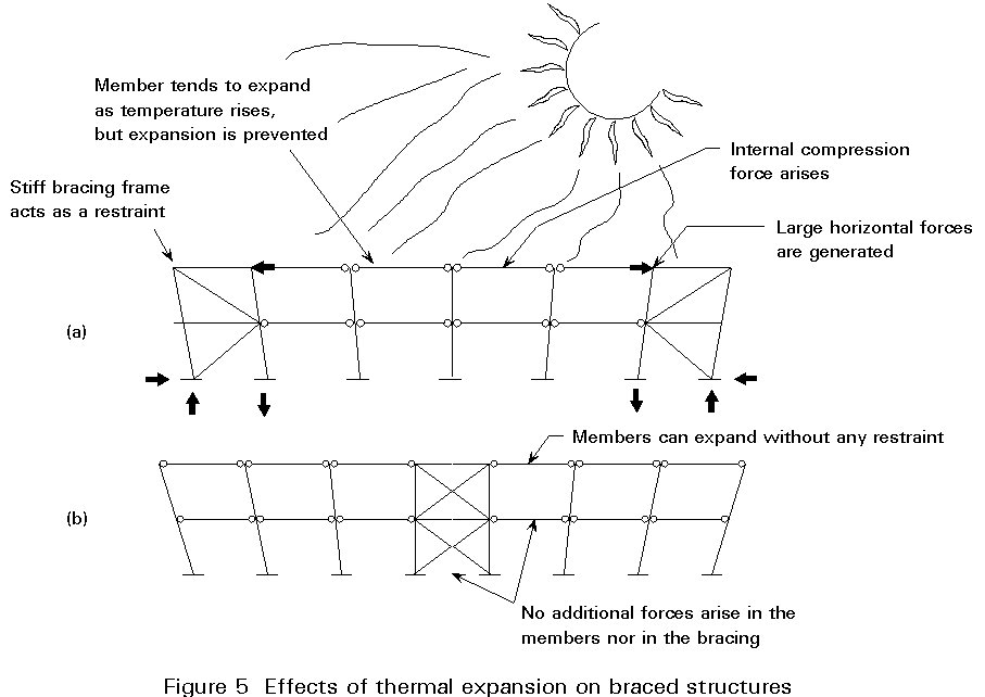
Thermal effects can be taken into account by adopting an appropriate temperature range (depending on the building location and usage) and a thermal coefficient of expansion for steel.
The structure should be analysed to ensure that the probability of reaching any of the limit states at which it would become unfit for its intended use within the design life of the building is acceptably low.
The ultimate limit state considers the strength and stability requirements of the structure - essentially a collapse criterion. Individual types of characteristic loadings are multiplied by the relevant factors to derive the design loads, and applied in the most unfavourable realistic combination for the element or overall structural response being considered. A simplified expression when considering only the most unfavourable variable action is of the following form:
Fd = ![]()
where
Fd is the design action
Gk is the characteristic permanent load
Qk is the characteristic variable load
g
G is the permanent load factorg
Q is the variable load factorThe load factors proposed in Eurocode 3 [1] when designing for the ultimate limit state are given in Table 1. It should be noted that permanent actions are effectively the self weight of the elements of the structure and of non-structural elements, whilst variable actions are the applied loads, e.g. wind load, imposed floor load, settlement load, etc. Where more than one variable actions are considered to act co-existently, the load factors are reduced to reflect the reduced probability of this combination of loading actually occurring on the real structure, i.e.:
Fd = ![]()
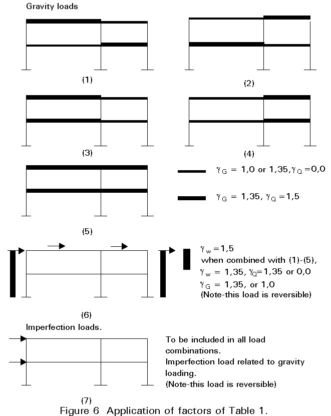
Figure 6 shows how these load factors may be applied to determine the most critical design conditions for a range of different frame types. The allowance for imperfections is explained in Section 6.
The serviceability limit state for steelwork addresses the following:
Eurocode 3 [1] presents guidelines to ensure that these limits are not exceeded.
When assessing the serviceability performance of the structure subject to a single variable load in addition to the permanent (self weight) load, the load factors are unity. The structure is effectively analysed using the characteristic actions. However, where the serviceability response of the structure is being assessed with more than one variable action, or where the dynamic response is being considered, Eurocode 3 [1] introduces three types of combinations of loading:
![]()
![]()
![]()
The factors in the above formula (yo, y1 and y2 ) vary and are detailed in the individual National Application Documents for Eurocode 3 of the various Member States. The rare combination, as the name suggests, considers a larger proportion of the variable action compared to that assumed in the frequent combination. It is a requirement in Eurocode 3 that the rare combination of loading is considered when conducting an appraisal of the member or overall frame deflections, whereas the frequent combination of load is considered when the dynamic response of the structure is being assessed.
When analysing a principle structural frame, it is important to classify it as being either sway or non-sway, braced or unbraced. The classification of the frame determines the method of global analysis which may be employed and the influence of secondary effects on frame actions (see Lecture 14.8).
The frame is classified as braced or unbraced depending on the relative stiffness of the bracing system providing the resistance to lateral forces.
The criterion for a braced frame is that the bracing system is at least five times stiffer than the lateral stiffness of the frame. It should be noted that this requirement will automatically be satisfied for simple frames incorporating bracing systems. In the absence of a bracing system a simple frame has zero lateral stiffness.
For a frame which is deemed to be braced, the bracing system must be designed to resist all lateral loads applied to the structure including those arising due to frame imperfections, see Section 6.
A frame which is classified as braced is automatically designed as non-sway. A frame which is deemed to be unbraced must be further classified as either sway or non-sway.
A frame is classified as non-sway for a given load case if the following criterion is satisfied:
![]()
where
Vsd is the design value of the total vertical load
Vcr is the elastic critical load for failure of the frame in a sway mode.
For multi-storey beam-and-column plane frames, with beams connecting each column at each storey level, classification as non-sway can be made for a given load combination, simply by determining whether the following condition is satisfied:
![]()
where
d
is the deflection over a storey height (interstorey drift)h is the storey height
V is the vertical reaction at the bottom of a storey
H is the horizontal reaction at the bottom of a storey.
Frames classified as sway must subsequently be checked for overall sway stability using the procedures given in Eurocode 3 [1].
The effects of frame imperfections must be included in the global analysis of any frame. Effectively, the imperfections are treated as a load case to be used in conjunction with all the critical load combinations acting on the frame.
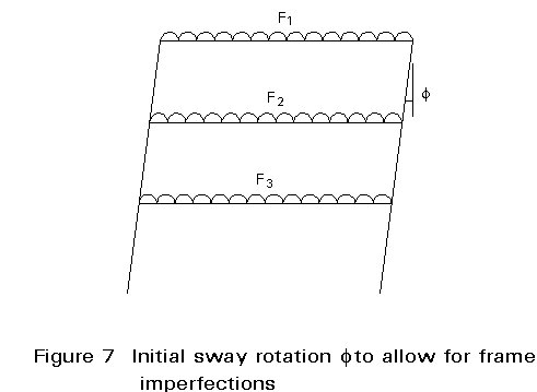
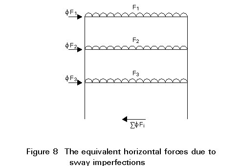
In Eurocode 3 [1], imperfection effects are quantified in terms of an initial sway rotation at the base of the column (see Figure 7), but may then be converted to an equivalent horizontal force (see Figure 8).
The initial sway imperfections f may be determined directly from Table 3. The number of columns nc includes only the main load bearing columns (i.e. only those which carry over 50% of the average load taken by all the columns in the frame being considered) which extend through all the storeys considered when evaluating ns. Similarly, the number of storeys ns only includes those floor and roof levels which are connected to all the columns included in evaluating nc. A single value of f is adopted for the whole frame. If the column arrangement is such that it is possible to calculate more than one value, it is permissible to choose the value which has the most beneficial effect. Alternatively, any other choice will be conservative. The values of f range from an upper bound of 1/200 to a lower limit of about 1/630.
The equivalent horizontal force fF at each roof and floor level is calculated by multiplying the proportion of the vertical load, F, applied at that level by the initial sway imperfection, f (see Figure 8).
The equivalent horizontal forces may be applied in any horizontal direction, but only in one direction at a time.
At the supports, the equivalent horizontal forces obtained by multiplying the vertical reactions by f are applied so that the equivalent horizontal forces on the whole frame form a closed system, which results in a net horizontal reaction of zero in the absence of actual horizontal loads.
It should be emphasised that the resulting equivalent horizontal forces should be applied in addition to any other horizontal forces which may be acting.
The modelling of structural systems will be covered in Annex H in a future addendum to Eurocode 3 [2]. In the meantime the following general principles apply.
It is conventional to assume that the members in a principle structural frame have centre lines intersecting at a point. The manner in which the design actions are distributed around the frame is dependant on the nature of the connections and the measures employed to resist lateral loading. Table 3, extracted from Eurocode 3, illustrates the different methods of global analysis which are permitted depending on the type of framing and connection.
The method for analysis and design of simple framing is dealt with at length in Lecture 14.10. The frame incorporates a separate bracing system which is designed to resist lateral loading and provide lateral stability to the part of the structure resisting gravity load (see Figure 9).

The model assumes the following:
As a result, the structure is statically determinate. The internal forces and moments are therefore determined from a consideration of statics.
Simple frames are invariably designed as non-sway (see Section 5) and, as a result, the effect of frame deformations on the distribution of internal forces and moments can be ignored.
Such structures are statically indeterminate. A detailed appraisal of the analysis and design of partial-strength (or partially continuous) frames is presented in Lecture 14.13, whilst those where full continuity is assumed at the connection are addressed in Lecture 14.14.
For continuous frames, the internal forces can be determined using either:
a. elastic global analysis.
b. plastic global analysis.
Whilst elastic methods of global analysis can be used throughout, plastic global analysis is only applicable where the frame members are of the appropriate classification to enable the development of plastic hinges.
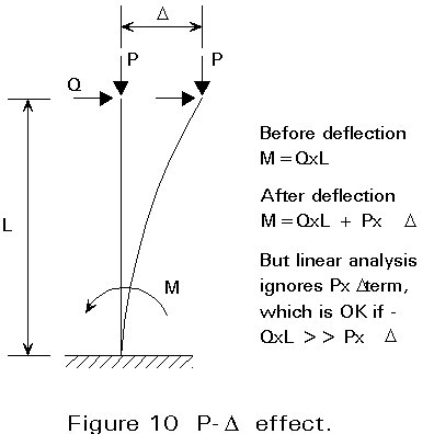
In a first-order analysis, the additional secondary actions due to the deformation of the structure (see Figure 10) are ignored.
This assumption is only valid in the following cases:
a. Where the frame is classified as braced (see Section 5.1).
b. Where the frame is classified as non-sway (see Section 5.2).
c. Where a design method is used in which an indirect allowance (amplification) is made for the occurrence of second-order effects.
In this latter case, the sway moments obtained from a first order linear elastic analysis are multiplied by the ratio:
(Formula 1) 1/[1 - Vsd/Vcr], for Vsd/Vcr £ 0,25
where
Vsd is the design value of the total vertical load.
Vcr is the elastic critical value in a sway mode.
For conventional framed structures, the ratio Vsd/Vcr can be determined as follows:
![]()
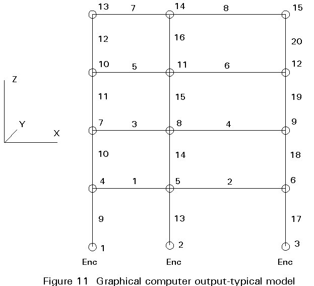
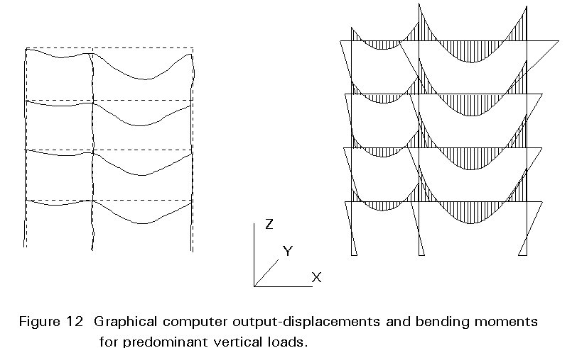
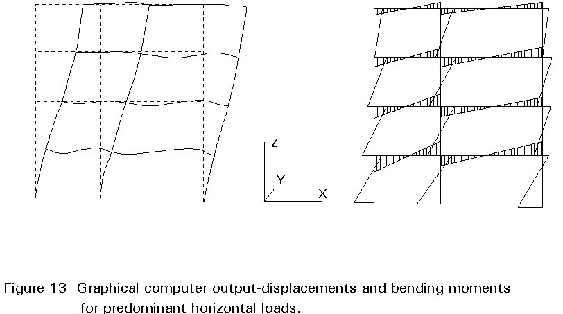
The first order elastic method of analysis is a convenient approach. Most design offices possess computer software capable of performing this method of analysis on large highly indeterminate structures. Figures 11 - 13 show typical graphical output from first order analysis made using computer software.
As an alternative, hand calculations can be performed on appropriate subframes within the structure (see Figure 14) comprising a significantly reduced number of members. These simple calculations are also recommended to make some physical check of the out-put of the computer.
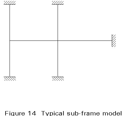
When conducting the analysis of an isolated subframe it is important that:
a. The subframe is indeed representative of the structure as a whole.
b. The selected boundary conditions are appropriate.
c. Account is taken of the possible adverse effects between adjacent subframes.
Plastic global analysis may be made by means of either:
Elastic-plastic methods require quite sophisticated computer programs, which enable second order effects to be taken into account.
As a design tool, Eurocode 3 [1] does present a method of rigid plastic analysis which takes into account secondary effects by amplifying the design internal forces and moments by means of the ratio given in Formula (1). The method is only applicable where frames have fixed bases and the only hinge to form in the column is at the base (see Figure 15) and the VSd/Vcr ratio does not exceed 0,2.
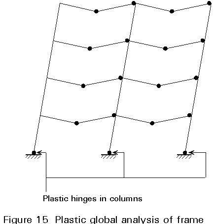
By means of this method the design is based on an incomplete mechanism in which the columns are designed to remain elastic at the calculated plastic hinge moment.
For building structures in which the required rotations are not calculated, all members containing plastic hinges shall have Class 1 cross-sections at the plastic hinge location.
[1] Eurocode 3: "Design of Steel Structures": ENV1993-1-1: Part 1.1: General rules and rules for buildings, CEN, 1992.
[2] Eurocode 3: "Design of Steel Structures": Annex H: Modelling of Building Structures for Analysis (in preparation).
|
Permanent actions (gG) |
Variable actions (gQ) |
||
|
Leading variable action |
Accompanying variable actions |
||
|
Favourable effect gF,inf |
1,0*) |
0,0 |
0,0 |
|
Unfavourable effect gF,sup |
1,35*) |
1,5 |
1,5 |
Table 1: Load factors in Eurocode 3
|
Type of framing |
Method of global analysis |
Types of connections |
|
Simple |
Pin joints |
Nominally pinned Nominally pinned |
|
Continuous |
Elastic |
Rigid Nominally pinned (6.4.3.1) |
|
Rigid-Plastic |
Full-strength Nominally pinned |
|
|
Elastic-Plastic |
Full-strength Rigid Nominally pinned |
|
|
Semi-continuous |
Elastic |
Semi-rigid Rigid Nominally pinned |
|
Rigid-Plastic |
Partial-strength Full-strength Nominally pinned |
|
|
Elastic-Plastic |
Partial-strength Semi-rigid Partial-strength Rigid Full-strength Semi-rigid Full-strength Rigid Nominally pinned |
Table 2: Methods of global analysis given in Eurocode 3 for different types of frame and connection
|
nc ns |
2 |
3 |
4 |
5 |
6 |
7 |
8 |
|
1 |
1/200 |
1/220 |
1/230 |
1/240 |
1/245 |
1/250 |
1/255 |
|
2 |
1/240 |
1/260 |
1/275 |
1/285 |
1/290 |
1/295 |
1/300 |
|
3 |
1/275 |
1/300 |
1/315 |
1/325 |
1/335 |
1/345 |
1/375 |
|
4 |
1/300 |
1/325 |
1/345 |
1/355 |
1/365 |
1/375 |
1/400 |
|
5 |
1/315 |
1/350 |
1/365 |
1/375 |
1/385 |
1/400 |
1/400 |
|
6 |
1/325 |
1/360 |
1/375 |
1/390 |
1/400 |
1/400 |
1/400 |
|
ns is the number of storeys nc is the number of columns per plane f = kc ks f0 with f0 = 1/200 kc = √{0,5 + 1/nc} ≤ 1 ks = √{0,2 + 1/nc} ≤ 1 |
|||||||
Table 3: Sway imperfection f