ESDEP WG 1B
STEEL CONSTRUCTION:
INTRODUCTION TO DESIGN
To present preliminary topics in designing multi-storey buildings.
An understanding of design philosophies and structural arrangements.
Lecture 1B.1: Process of Design
Lecture 1B.2.1: Design Philosophies
Lecture 1B.2.2: Limit State Design Philosophy and Partial Safety Factors
Lecture 1B.3: Background to Loadings
The lecture gives a brief description of the fundamental components of a building frame. It presents different structural arrangements to resist horizontal and vertical loadings. Finally, consideration is given to the question of fire protection.
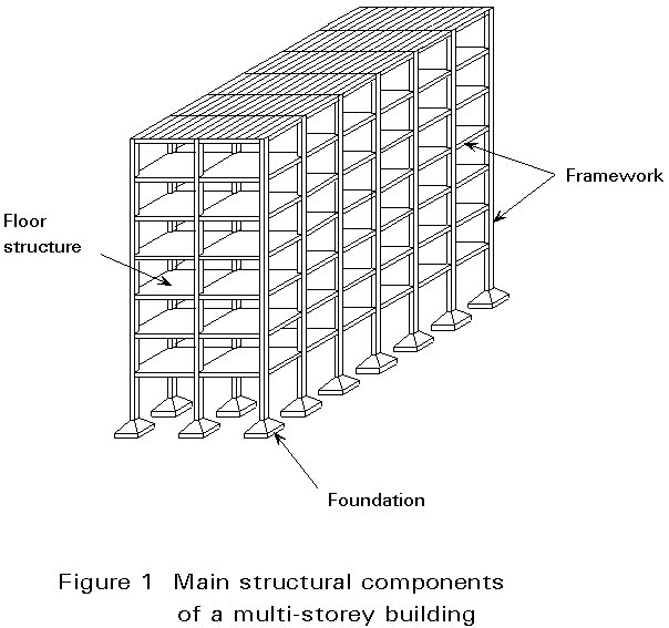
A multi-storey building must resist the combined effects of horizontal and vertical loads; it is composed of foundations, frameworks and floor slabs.
The framework comprises columns and beams together with horizontal and vertical bracings, which stabilise the building by resisting horizontal actions (wind and seismic loads).
Floor slabs are supported by beams so that their vertical loads are transmitted to the columns. They are made of reinforced concrete or composite slabs using profiled steel sheets. Columns are commonly made of H or hollow hot-rolled steel sections. The use of hollow sections filled with concrete can improve their fire resistance. Beams are commonly made of I and H profiles. Nevertheless, the use of welded built-up sections can offer more rational solutions in some cases.
The usual structural systems belong essentially to two categories: moment resisting frame systems and braced-frame systems, the second being the simplest and, therefore, the most economic solution.
In braced frames, vertical bracings are formed by diagonal members within the steel frame. These bracings may be of different form (cross-braced X shaped; V or inverted V shaped; symmetrical or unsymmetrical portal). Alternatives to steel bracings are the reinforced concrete shear walls or cores.
These main components of multi-storey buildings and their design are described in the following section:
A multi-storey building includes the following structural components (Figure 1):
a. foundations
b. framework
c. floor structures.
Foundations are made of reinforced concrete. The type of foundation is selected according to the features of the ground and the ground conditions.
The framework is the steel skeleton which provides the load-bearing resistance of the structure and supports the secondary elements such as the floor slab and cladding.
All external loads, both vertical and horizontal, are transmitted to the foundations by means of the steel framework. It is mainly composed of vertical elements (columns) and horizontal elements (beams), which may be connected together in different ways. According to the degree of restraint at the beam-to-column connections, the framework can be considered as 'rigid', 'semi-rigid' or 'pin-ended'. For the pin-ended case, the framework must incorporate bracing elements which are located in the rectangular panels bounded by columns and beams.
The floor slabs are required to resist the vertical loads directly acting on them and to transmit these loads to the supporting floor beams. They also transfer the horizontal loads to the points on the framework where the bracing members are located.
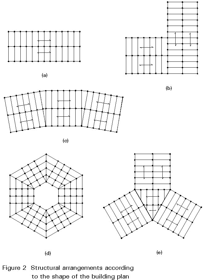
The structural arrangement of multi-storey buildings is often inspired by the shape of the building plan, resulting in different solutions (Figure 2). The plan can be rectangular (Figure 2a), L-shaped (Figure 2b), curved (Figure 2c), polygonal (Figure 2d) or perhaps composed of rectangular and triangular elements (Figure 2e).
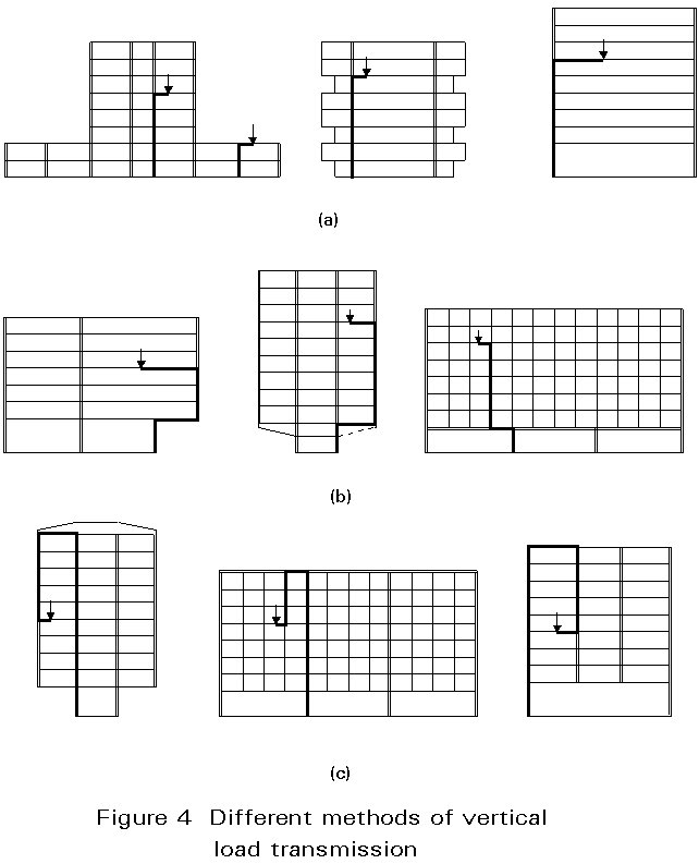
Columns are the structural components which transmit all vertical loads from the floors to the foundations. The means of transmission of vertical load is related to the particular structural system used for the framework (Figure 4).
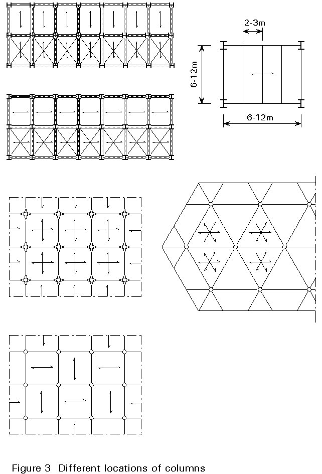
The location of columns in plan is governed by the structural lay-out. The most common grid arrangements are square, rectangular, or occasionally triangular, according to the choice of the global structural system (Figure 3). The spacing of columns depends upon the load-bearing resistance of the beams and floor structures. It can vary from 3 to 20m, but is typically in the range of 6 to 10m.
Load transmission from floors to columns may occur directly from the floor beams to the column (Figure 4a), or it can be indirect. Indirect transmission involves the use of major 'transfer' beams (Figure 4b), which resist all the loads transmitted by the columns above.
In suspended systems (Figure 4c), the transmission of vertical loads is much more complicated. It is directly provided by tensile members (ties), hung from the top beam elements which support the total vertical load of all floors. A limited number of large columns provide the transmission of the total load to the foundations.
The choice of location and spacing of columns depends on the structural system which has to harmonize functional and economical requirements.
The shapes of cross-section commonly used for columns can be subdivided into (Figure 5):
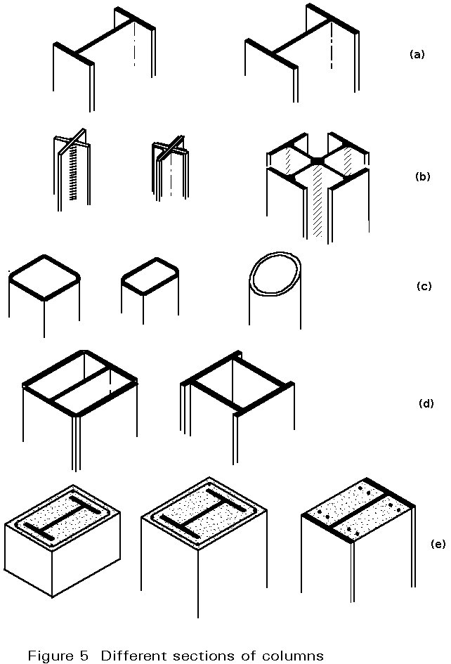
Open sections are basically standard hot-rolled I and H profiles (Figure 5a). Double-T sections can be also built up by welding. Cross-shaped sections can be obtained by welding L profiles, plates or double-T profiles (Figure 5b).
Hollow sections are tubes of circular, square or rectangular cross-section (Figure 5c). They can also be made from plates or double-T profiles by welding (Figure 5d).
Circular and square hollow sections have the advantage that they have the same resistance in the two principal directions, enabling the minimum section dimensions to be obtained. Sometimes hollow sections are filled with concrete, giving an increase in strength and, at the same time, achieving significant fire resistance (> 60 minutes) (Figure 5e). However the beam-to-column connections are more complicated than between I-sections.
Beams support the floor elements and transmit their vertical loads to the columns.
In a typical rectangular building frame the beams comprise the horizontal members which span between adjacent columns; secondary beams may also be used to transmit the floor loading to the main (or primary) beams.
In multi-storey buildings the most common section shapes for beams are the hot rolled I (Figure 6a) or H shapes (Figure 6c) with depth ranging from 80 to 600mm. In some cases channels, (either single or double) can also be used (Figure 6b).
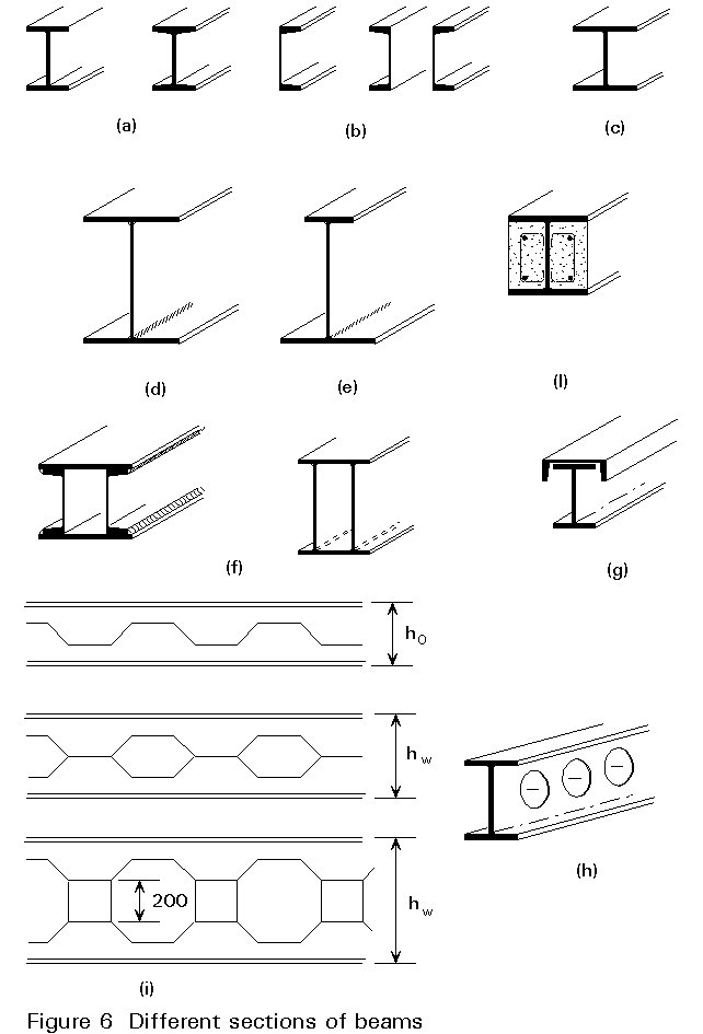
Where a greater depth is necessary, built-up sections can be used. Sections fabricated by welding can have double-symmetrical (Figure 6d) or non-symmetrical (Figure 6e) shape, the latter being advantageous for composite steel-concrete sections. By combining plates and/or profiles, box-sections (Figure 6f) or open sections (Figure 6g) can be fabricated.
Sometimes openings in the webs of beams are required in order to permit the passage of horizontal services, such as pipes (for water and gas), cables (for electricity and telephone), ducts (for air conditioning), etc. The openings may be circular (Figure 6h) or square with suitable stiffeners in the web. Another solution to this problem is given by using castellated beams (Figure 6i), which are composed by welding together the two parts of a double-T profile, whose web has been previously cut along a trapezoidal line.
For buildings, the common range for the span to depth ratio is 15 to 30 in order to achieve most efficient design.
In addition to the strength, beams must provide enough stiffness to avoid large deflections which could be incompatible with non-structural components (such as partition walls). For this purpose the maximum mid-span deflection of a beam is usually limited to a fraction of the span equal to 1/400 - 1/500. Where this limitation is too severe, an appropriate initial deformation (camber) equal and opposite to that due to the permanent loads can be pre-formed into the beam.
Steel sections can be partly encased in concrete by filling between the flanges of the section. Partly encased sections are fire resisting without conventional fire protection (Figure 5e). For longer periods of fire resistance, additional reinforcing bars are required.
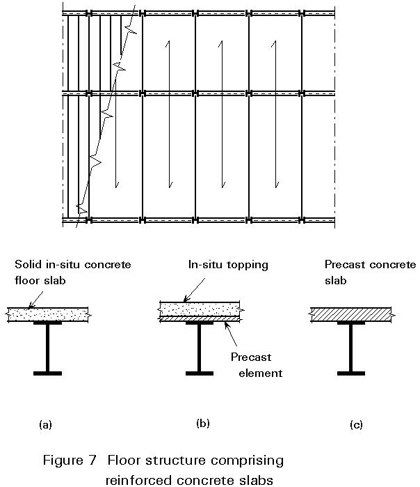
Floor are required to resist vertical loads directly acting on them. They usually consist of slabs which are supported by the secondary steel beams. The spacing of supporting beams must be compatible with the resistance of the floor slabs. Floor slabs may be made from pre-cast concrete, in-situ concrete or composite slabs using steel decking. A number of options are available:
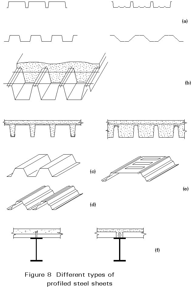
Typical spans for concrete slabs are 4m to 7m, thus avoiding the need for secondary beams. For composite slabs, various cross-section shapes of steel decking are available (Figure 8a). They are classified in three categories according to their load-carrying resistance:
Deck spans range in length from 2 to 4m for the first category, from 3 to 5m for the second category, and from 5 to 7m for the third category. Secondary floor beams can be avoided in the last case.
Permissible spans for steel decking are influenced by conditions of execution, in particular whether temporary propping is used. Such propping is best avoided since the principal advantage of using steel decking, i.e. speed, is otherwise diminished.
To increase the strength and stiffness of the floor beams, a composite steel-concrete system can be obtained by means of appropriate studs welded on the top of the flange (Figure 8f). In this case the slab and beam may be designed compositely using conventional theory.
Bracing systems are used to resist horizontal forces (wind load, seismic action) and to transmit them to the foundations.
When a horizontal load F (Figure 9a) is concentrated at any point of the facade of the building, it is transmitted to two adjacent floors by means of the cladding elements (Figure 9b).
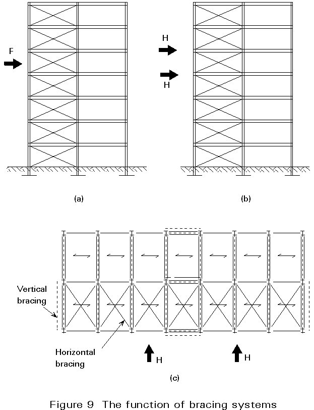
The effects of loads H acting in the floor slab are distributed to the vertical supporting elements which are located in strategic positions of the structural layout (dotted lines in Figure 8c) by means of an appropriate horizontal resisting element in the floor.
The vertical supporting elements are called vertical bracings; the horizontal resisting element is the horizontal bracing which is located at each floor.
Where horizontal bracings are necessary, they are in the form of diagonal members in the plan of each floor, as shown in Figure 9c).
If steel decking is used, the diagonal bracing can be replaced by diaphragm action of the steel sheeting if it is fixed adequately.
Both horizontal and vertical bracings represent together the global bracing system, which provides the transfer of all horizontal forces to the foundations.
Vertical bracings are characterised by different arrangements of the diagonal members in the steel frame. They are (Figure 10):
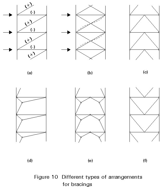
a. Single diagonal
b. Cross-braced (X-shaped bracing)
c. Inverted V-shaped bracing
d. Unsymmetrical portal
e. Symmetrical portal
f. V-shaped bracing.
An alternative to steel bracings is provided by reinforced concrete walls or cores which are designed to resist the horizontal forces (Figure 11). In these systems, so-called dual systems, the steel skeleton is subjected to vertical forces only. Reinforced concrete cores are usually located around the stairway and elevator zones.
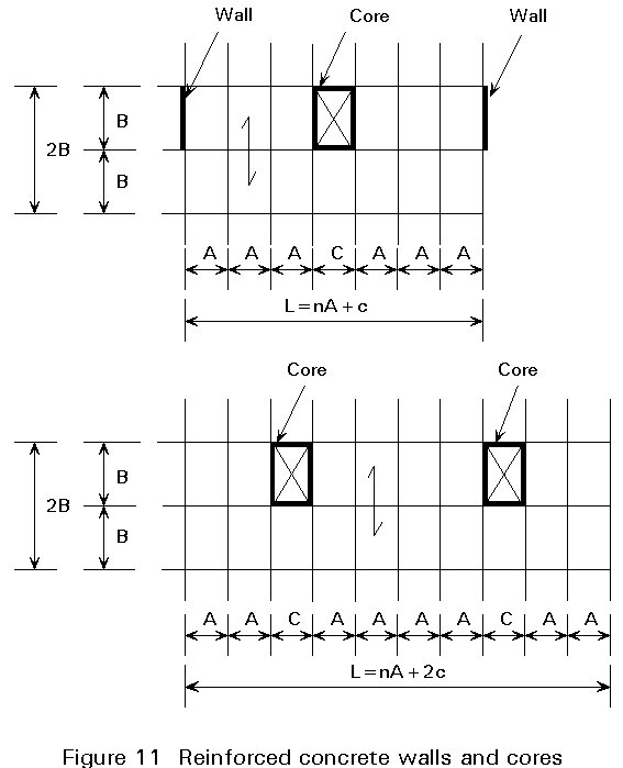
Normally, the floor slab can be designed to resist in-plane forces to avoid the use of horizontal diagonals. This is the case for in-situ reinforced concrete slabs, or composite slabs with appropriate shear connectors.
To provide resistance to the combined effects of horizontal and vertical loads in a multistorey building, two alternative concepts are possible for the structural system.
The first, so-called 'moment resisting frame system', is a combination of horizontal (beams) and vertical (columns) members which are able to resist axial, bending and shear actions. In this system no bracing elements are necessary. The moment resisting frame behaviour is obtained only if the beam-to-column connections are rigid, leading to a framed structure with a high degree of redundancy. As a consequence of this choice:
Typical details of beam-to-column joints for rigid framed systems are shown in Figure 12. They are called 'rigid joints' and their task is to transfer bending moment from the beam to the column. Type (a) can transfer limited bending moments only because the column web can buckle due to local concentration of effects. The presence of horizontal stiffeners in the column web (Type (b)) recreates the cross-section of the beam and the column web panel has to resist the shear force only.
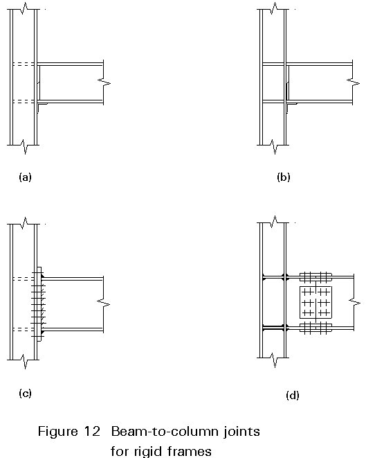
Types (a) and (b) require the execution of welding operations on site. Such operations are not completely reliable and they are also expensive and can cause delay in erection.
A better alternative is to use bolted connections which allow rigid joints to be made without the disadvantages of site welds. Two typical solutions for rigid frame structures, shown in Figures 12c and 12d, are:
These solutions allow the most suitable use of connecting methods, i.e. welding in the shop to build up prefabricated elements and bolting in site for connecting them together. This type of joint can be, therefore, called 'shop-welded field-bolted'.
To avoid the practical problems of rigid frame construction, a more convenient solution can be obtained by conceiving the structural behaviour in a different way. The functions of resistance to vertical and horizontal loads are separated in the different 'families' of members, which are grouped in two sub-structures (Figure 13):
a. a simple frame composed by beams pinned together, which is capable of transferring the vertical loads to the foundation (Figure 13a).
b. a cantilever fixed to the ground which resists horizontal forces and transfers their effects to the foundation (Figure 13b).
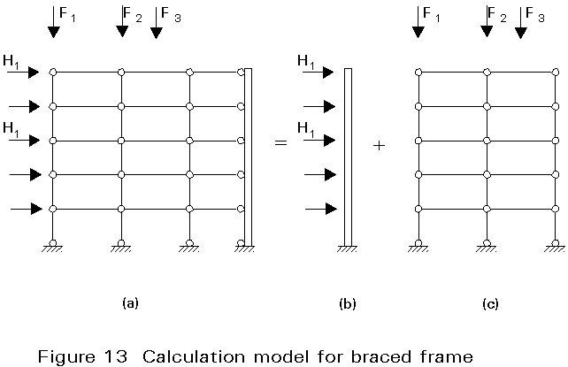
Sub-structure a. is hyperstatic; beams are bent in the vertical plane, columns are simply compressed, the hinged joints between beams and columns absorb shear forces only.
Sub-structure b. is isostatic; its bracing function can be obtained by means of steel trusses or by reinforced concrete walls. These bracing structures are mainly loaded in shear and bending and their deformability must be checked under serviceability conditions in order to limit sway.
The combination of both sub-structures a. and b. provides the complete structure (Figure 13c), which is able to resist both vertical and horizontal loads.
The main advantages of this solution, the so-called 'braced-frame system', are:
In contrast, some complications arise in the foundation of bracings which must resist the overall horizontal forces with a very small amount of axial compression. High values of eccentricity occur which require large dimensions of the contact area under the foundation.
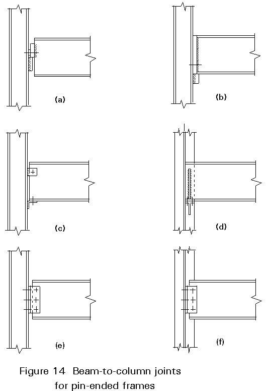
In these structural systems beam-to-column joints must resist only axial and shear forces. Some typical solutions of joints for pin-ended structures are shown in Figure 14; they are 'shop-welded field-bolted' joints. The most commonly used is the bolted connection between the beam web and the column flange (or web) by means of double angles (Figure 14e, f). They are more economic than the fully welded solutions (Figure 12a, b) for rigid structures and allow simple erection.
The design of a structural system for a multi-storey building must to take into account its spatial behaviour.
For the 'braced frame system', which seems to be most convenient for economy and reliability, it is necessary to locate a sufficient number of bracings to allow any horizontal loads however directed to be resisted. For this purpose, the requirements are:
(1) it must be possible to consider any floor system as a plane structure, restrained by the vertical bracings.
(2) bracings, as external restraints of the floor system, must provide a system of at least three degrees of restraint.
(3) the floor system must be capable of resisting the internal forces due to the applied horizontal loads.
To fulfil requirement (1), diagonal bracings must be introduced in the plane of the floor, thus transforming the floor system itself into a horizontal truss.
As an alternative, the slab of prefabricated concrete elements in the floor system can be assumed to resist directly the horizontal forces as a plane plate structure, because its deformability is normally negligible.
Where concrete slabs are used, the erection of the steel skeleton requires particular care, because it is unstable until the floor elements are placed. Temporary bracing is therefore necessary during this phase of execution.
To fulfil requirement (2) the steel truss bracings are active only in their own plane and therefore represent a simple restraint for the floor system. When reinforced concrete bracings are used, they can have one, two or three degrees of restraint, depending upon their resistance to one plane bending (wall), bi-axial bending or bi-axial bending and torsion (core), respectively.
Finally, requirement (3) is fulfilled by evaluating internal forces in the floor elements due to the horizontal loads by considering the location of the vertical bracings.
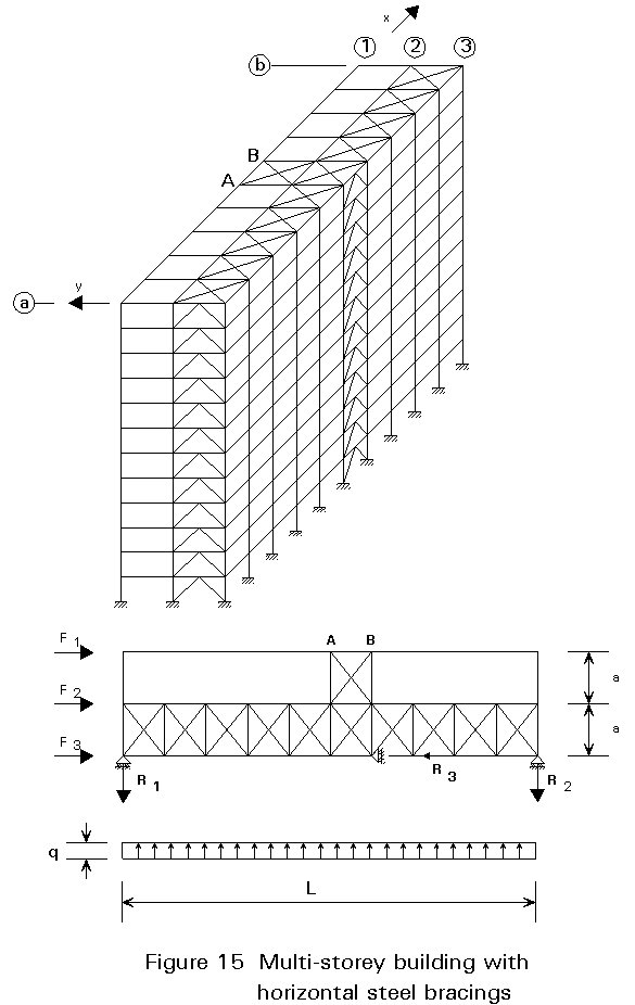
Figure 15 shows a three-dimensional structure for a multi-storey building with steel bracings. Every point of the floor system is fixed in two directions. In particular, the diagonals connecting points A and B restrain all the points in line '1' in the 'x' direction. The floor bracing is able to receive external forces from both direction 'x' and 'y' and to transmit them to the vertical bracings.
The spatial structure can be reduced to plane sub-structures whose static schemes are shown in Figure 16. The longitudinal facade along row '3' is directly braced in its plane as well as the lateral facades by the transverse bracings of axes 'a' and 'b'.
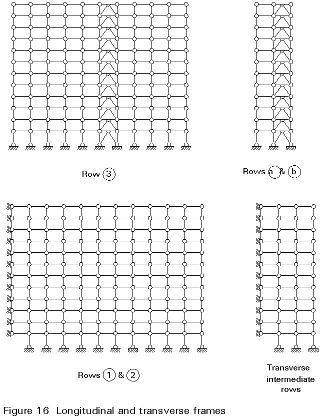
The pinned joints of the intermediate transverse frames and of the longitudinal frames of axes '1' and '2' are prevented from any horizontal displacement because they are all connected to the vertical bracings by means of the floor bracings. Thus they can be considered as non-sway frames.
Figure 17 represents the spatial structural scheme of a multi-storey building with a reinforced concrete bracing core. It can be considered as an alternative solution of the previous example for the same building, in which the concrete core substitutes both longitudinal and transverse steel bracings.
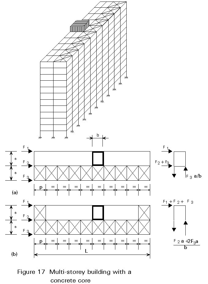
Two floor bracing systems can be considered:
If all the four walls of the staircase core are structurally effective, the solution of Figure 17a is correct. If only three sides of the staircase core are structurally effective, the transmission of the horizontal forces acting in the longitudinal direction to the longitudinal wall requires the use of additional floor diagonals, as shown in Figure 17b.