ESDEP WG 1B
STEEL CONSTRUCTION: INTRODUCTION TO DESIGN
To continue the introduction to steel and composite bridges. To describe footbridges, moving bridges and service bridges. To provide initial guidance in selection of bridge form and span.
Lecture 1B.6.1: Introduction to the Design of Steel and Composite Bridges: Part 1
Lectures 15B: Structural Systems: Bridges
This lecture continues the introduction to steel and composite bridges started in Lecture 1B.6.1. It describes three types of special bridge, highlighting some of the features in design. Footbridges are narrow, lightly loaded structures frequently in visually sensitive locations. Moving bridges are subject to particular constraints of geometry and mass. Services bridges offer special opportunities for innovative design. The lecture concludes with some guidance on the appropriate selection of bridge form and on the determination of optimum spans for viaducts.
In Lecture 1B.6.1 attention was concentrated both on the principal design parameters and the various structural forms that a designer may consider when carrying out the preliminary or conceptual design of a bridge. It is probably safe to say that the large majority of bridges are fixed structures carrying a road or railway and it is easy to see how the types discussed can be used for such bridges. In this second part of the Lectures 1B.6, attention will first be given to particular considerations affecting some special types of bridge. Three types will be discussed - footbridges, moving bridges and service bridges (pipelines, etc.). Some guidance on choice of bridge type and span is also provided.
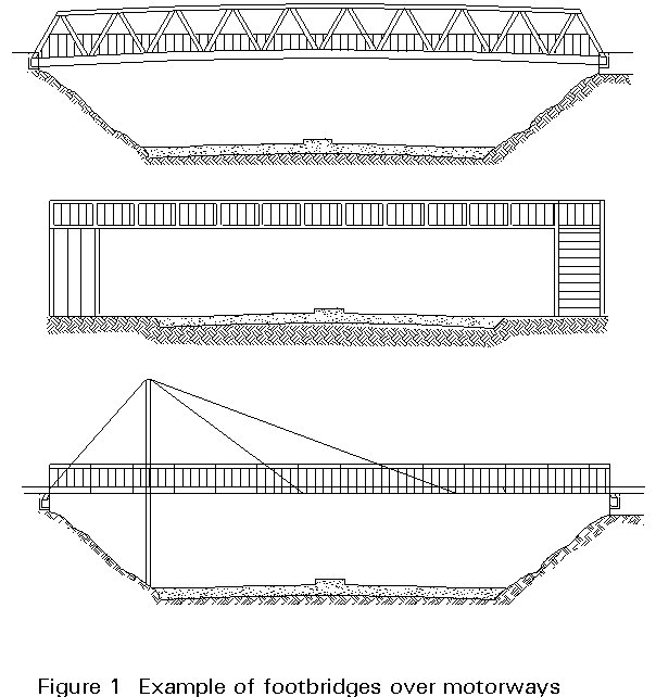
Footbridges are needed where a separate pathway has to be provided for people to cross traffic flows or some physical obstacle, such as a river. The loads they carry are, in relation to highway or railway bridges, quite modest, and in most circumstances a fairly light structure is called for. They are, however, frequently required to give a long clear span, and stiffness then becomes an important consideration. These bridges are often very clearly on view to the public and then the appearance merits careful attention. Steel offers economic and attractive forms of construction which suit all the requirements demanded of a footbridge. Figure 1 gives schematic views of a range of structural forms in steel.
Like any other bridge, footbridges must be long enough to clear the obstacle which is to be crossed and high enough not to interfere with whatever passes beneath the bridge. However, the access route onto the footbridge is often quite different from that which is familiar to the designer of a highway bridge: there is no necessity for a gentle horizontal alignment (indeed the preferred route may be sharply at right angles to the span). Structural continuity is, therefore, less common; the principal span is often a simply supported one.
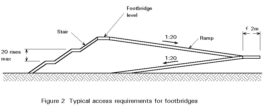
Provision of suitable access for wheelchairs and cyclists is often specified for footbridges, see Figure 2. Access ramps must be provided and restricted to a maximum gradient. The consequent length of ramps where access is from the level of the road over which the bridge spans is generally much longer than the bridge itself. The form of construction suitable for the ramps may have a dominant influence on the form of the bridge.
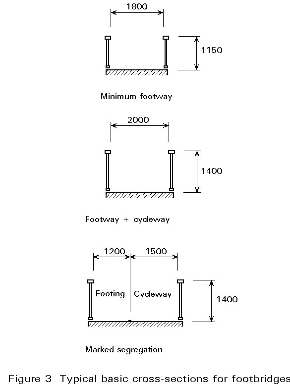
As shown in Figure 3, the width of a footbridge is usually quite modest, just sufficient to permit free passage in both directions for pedestrians. Occasionally the bridge will have segregated provision for pedestrians and cyclists, in which case it will need to be wider.
Parapets are provided for the safety of both the pedestrians and traffic below. Footbridges over railway lines may be required to have higher parapets and be provided with solid panels directly over the rail tracks.
A fixed bridge to take a highway or railway over a navigable waterway in flat country will require very long approach works. Even a typical highway with a limiting approach gradient of 4%, will require an approach length of 750m each side to give 30 metres clearance (not an unusual figure for a waterway which can be navigated by seagoing ships). This would be increased by the construction depth of the bridge. The length for a railway bridge, with its shallower gradients, would be even longer.
An alternative is to keep the bridge at low level and design it to open to allow the passage of ships. The primary advantage is that the construction cost of an opening bridge is almost invariably much less than that of a high level bridge (and very much less than that of the other possibility, a tunnel). In addition, in flat country for which the comparison is being made, a high level bridge can be visually very intrusive. The main disadvantage of a moving bridge, of course, is the delay to traffic when a bridge is opened to shipping; further disadvantages include the need for manning and maintenance of the opening system, the risk of failure thus disrupting either shipping or surface traffic, and the risk of ships colliding with and damaging the structure.
When the highway and waterway are main routes, there may be no alternative to using either a high level bridge or a tunnel. However, where an element of delay is acceptable, moving bridges are commonly used. The Netherlands and the flat eastern counties of the UK are two regions where there are many such structures.
The design of moving bridges is a highly specialised subject and can only be covered very briefly in general terms in this lecture. Modern moving bridges are likely to be one of three types - bascule, swing or lift, with bascule bridges probably being the most common. The main features of each are discussed briefly below.
A bascule bridge consists of one or two cantilever arms (or "leaves") which either pivot about horizontal axes at abutment piers (Figure 4a, b and d) or roll backwards on a track (Figure 4c). Normally, such bridges on railways or major highways are of single leaf construction, since they then behave as simply supported girders for carrying traffic loads; if a double leaf configuration is used, even the traffic loads are carried on cantilever structures which, in consequence, have to be of much stronger construction.
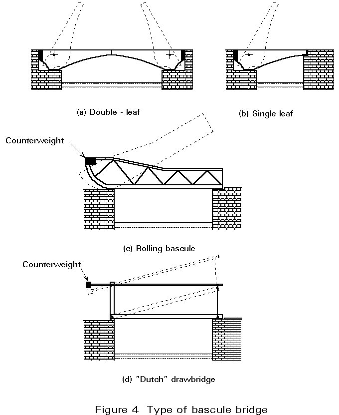
The main advantage of a bascule bridge is its efficiency in operation. Bascule leaves are fast to raise and lower, and for the passage of small vessels, need only be raised to part height, thus speeding the operation still further. Furthermore, unlike the swing bridge (see Section 3.3) they operate within the shadow area of the structure.
One disadvantage of the simple pivoting bascule bridge, as shown in Figures 4 (a) and (b), is that the mass of the cantilever has to be balanced whilst pivoting in order to keep the power requirements to a reasonable level,. This means either a significant backspan, with a very deep abutment pier to accommodate it after raising, or the use of a very substantial counterweight. This problem is partly overcome with the "Dutch drawbridge" type (Figure 4(d)) in which the counterweight is mounted on an overhead structure and thus does not need deep abutments to accommodate it.
A further disadvantage is the high power requirement for operating in adverse weather conditions. High winds blowing across a river cause very large forces on the bascule leaves, and snow loading will of course increase the raised mass without any compensating counterweight; additional demands arise on the drive and braking systems. It must be pointed out, of course, that the high reserve of power required for these conditions contributes materially to the efficient operation under normal conditions.
Whilst structurally efficient in most locations, a wide bascule bridge can give problems for a highly skewed crossing since the non-symmetrical shape of the leaves results in unbalanced forces during raising.
A swing bridge pivots about a vertical axis until the superstructure is aligned clear of shipping lanes (Figure 5). The main advantage of a swing bridge is that it probably has the lowest power requirements of any form of moving bridge. If the bridge is symmetrical (equal length swinging arms), wind effects during swinging are small since they will be largely balanced on the two arms and snow loading does not require additional power - the increased inertia merely results in a slightly longer time for swinging due to slower acceleration and braking.
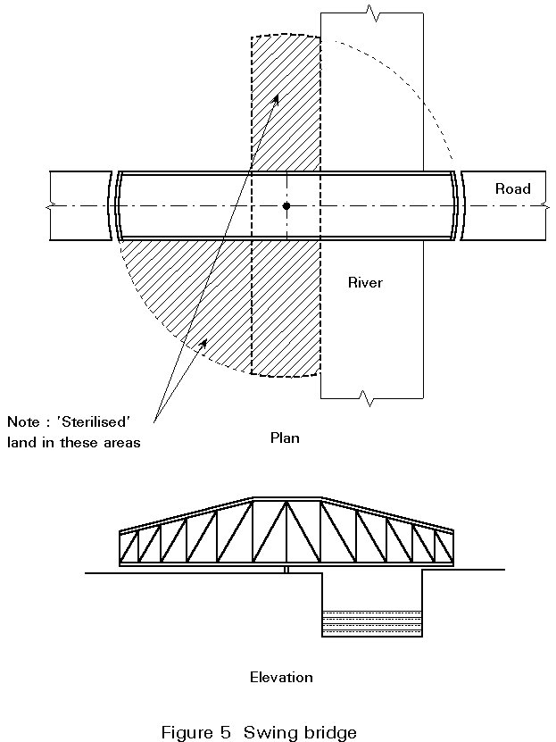
Structurally, a swing bridge is efficient, in that it can be made as a simple girder (either plated or truss) which cantilevers each side of the pivot pier during swinging, but rests on the abutments to give a two-span continuous beam when carrying traffic; if the cantilever span during swinging is excessive it is comparatively easy to design it as cable-stayed with a tower above the pivot pier. The primary purpose of the stays is to carry the dead load during swinging. A skew crossing is no problem for a swing bridge - indeed, it can even be an advantage since it reduces the arc of swing.
The main disadvantages of a swing bridge are the comparatively long time required for swinging from the traffic to the shipping position, and the large plan area required to accommodate the structure when opened for shipping; once swung, of course, it has the advantage that the vertical clearance ("air draught") is unlimited. A swing bridge will normally have to be fully swung for any vessel, regardless of size, since a partial opening will result in the risk of the vessel striking the structure. In addition, since there is usually only one shipping channel, the "backspan" is operationally unnecessary, and the additional structure is expensive. The extra structural cost can be minimised by making the backspan shorter and counterweighting it, but this will reduce some of the advantages listed above - for example, the wind load will no longer be balanced and hence more power will be needed to drive the bridge in high winds. Furthermore, snow loading will put an unbalanced vertical load on the structure. Perhaps the "ideal" location for a swing bridge is in a river with an island exactly in the middle, and shipping lanes either side!
In lift bridges the span is lifted up towers at each end to clear a shipping channel (Figure 6). Structurally, lift bridges are very efficient, since they are simply supported spans both in-service and during the raising operation. They are designed as girders (either plated or truss) and since they do not have to operate as cantilevers in any condition they can provide much longer opening spans than bascule or swing bridges.
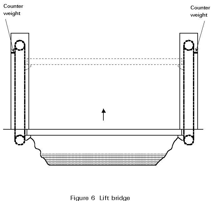
The main disadvantage of a lift bridge is that it can only give as much vertical clearance as is provided by the height of the towers; hence, if very large clearances are required, the towers become very expensive. As for bascule bridges, however, there is no need to raise the span fully for small vessels, thus improving the efficiency of operation. Furthermore, although the dead weight of the lift span will, of course, be counterweighted, an allowance in the drive system has to be made for the possibility of snow on the deck during raising.
Other types of moving bridge which have been used in the past (and occasionally at present) are:
All these types have serious operational and other disadvantages for almost all present-day applications.
Many, if not most bridges, whether road, rail or footbridges, also carry at least some public utility services (electricity, telephone, water, gas, etc.). Provision for carrying these services varies with the type of bridge - for instance, box girders provide an obvious area for routing them (although care must be taken to provide for accidents - a flooded box girder arising from a fractured internal water main could be disastrous!) On plate girder bridges it may prove possible to carry the services within the footpath, or hanging from cross-girders if the bridge is of that form of construction.
In this section, however, attention is focused on pure service bridges, whose purpose is only to carry a utility. Clearly, a service bridge may be of any of the fixed bridge types already described, but there are certain special considerations. The loading is usually very light compared with road or rail traffic, and hence some of the problems of footbridges arise here also. Perhaps the commonest form of service bridge is a simple light truss, although aesthetic considerations can rule this out in certain locations.
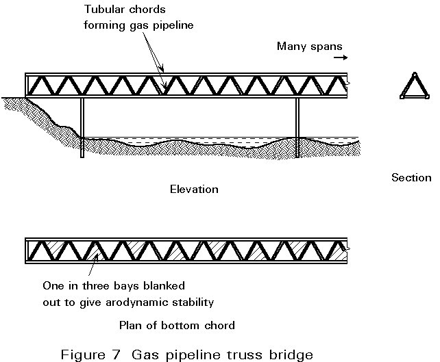
An interesting variation of the simple truss has been employed on occasion for services which require pipelines, e.g. gas or water. This involves making the truss chords from tubular members which service as the actual pipelines - one example of this is a tubular space truss of triangular cross-section carrying high pressure gas in its chords (Figure 7). A small problem occurred in that the tubular chords gave rise to a low level of aerodynamic excitation; whilst this was no immediate problem, there was concern over long term fatigue effects. A simple aerodynamic change to the section was devised to eliminate the excitation.
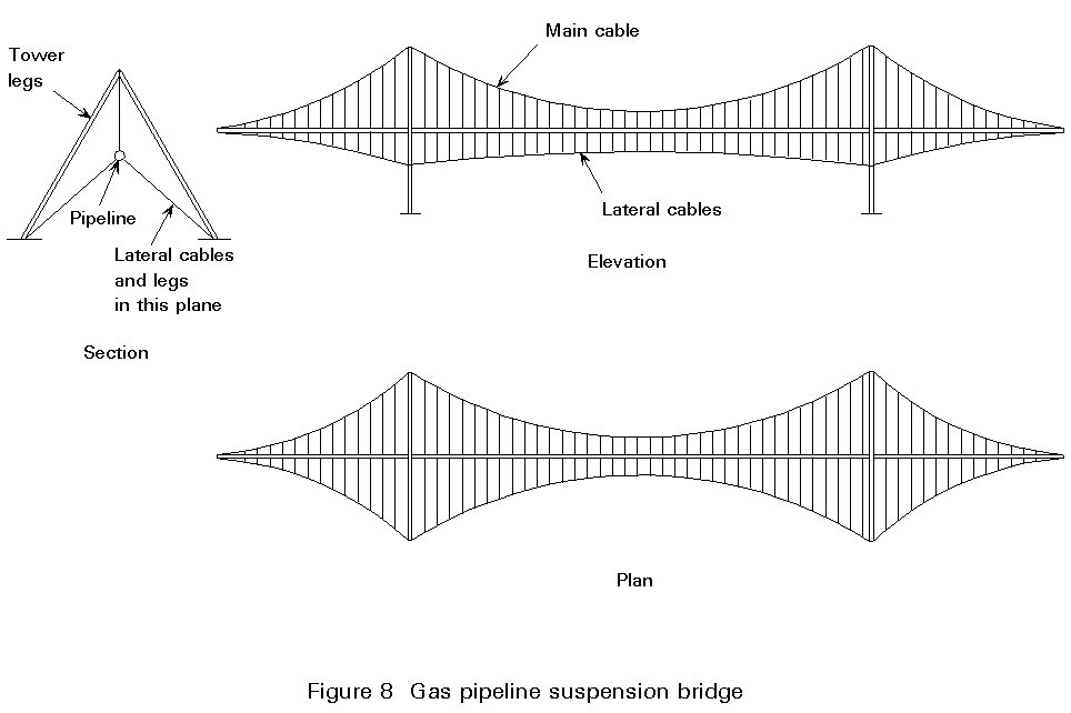
The use of cable structures is also common for service bridges. Sometimes the service itself provides this - an overhead electricity transmission line is, in effect, a large series of spans using the conductors as bridges. On long electricity crossings, it may be necessary to take special measures to remove any tendency to aerodynamic oscillation. Cable structures can also be sued for pipeline ridges, where the length is too great to allow the pipe to span unaided. In such a case, both suspension and cable-stayed bridges have been used, sometimes using the pipeline itself as the stiffening girder, and sometimes providing a separate girder.
It is likely, however, that if a suspension bridge type is chosen the dead weight will be so low that the structure will be unacceptably flexible. Furthermore, it will be very weak in the transverse direction when subjected to wind loading. A simple way of correcting both faults is to introduce two further cables on either side of the pipeline (or separate girder if provided), inclined downwards from it, and tensioned against the main suspension cable (Figure 8). This form of structure is very light, and well suited for use in areas where access is difficult for transporting heavy pieces.
Each form of bridge is suited to a particular range of spans, see Figure 9, which also records the longest span for each type of construction.
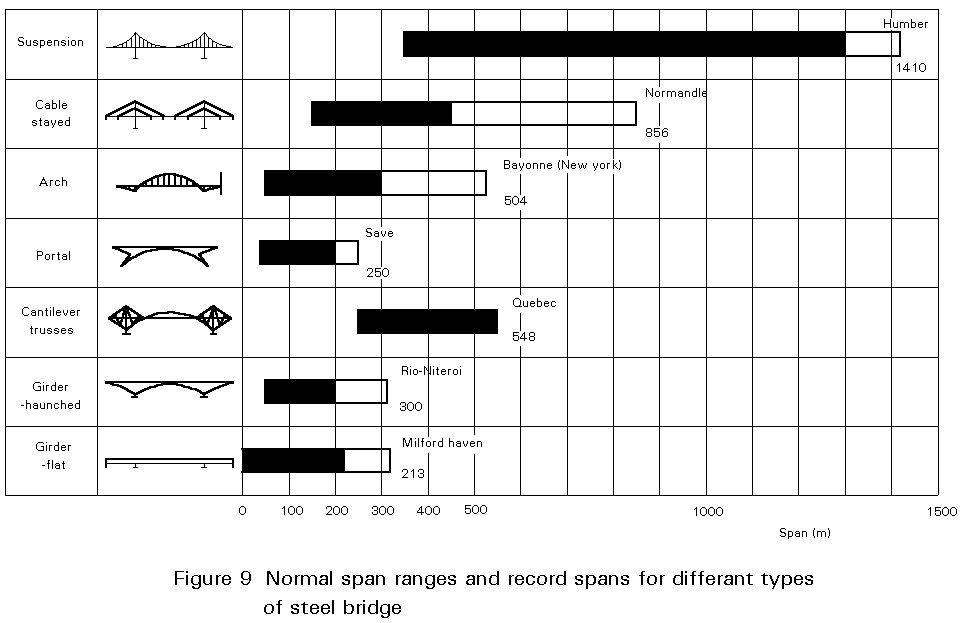
Suspension or cable stayed bridges are the only forms capable of achieving the longest spans. They are clearly less suitable for road or rail bridges of short or medium span. However, they can be appropriate for shorter span footbridges, partly because they do not have any concentrated loading that requires an expensive stiffening girder and partly for aesthetic considerations. (It should be noted that the same special consideration which is needed for long spans, such as aerodynamic stability, needs to be applied to steel footbridges).
Suspension bridges are still used for the longest spans where intermediate piers are not feasible. The cables are subjected to very high tension and are tied to the ground, usually by gravity foundations sometimes combined with rock anchors. Thus ground conditions with rock at or close to the surface of the ground are essential.
Cable stayed bridges are of suspension form with normally straight cables which are directly connected to the deck.
The structure is self anchoring and, therefore, less dependent on good ground conditions. However, the deck must be designed for the significant axial forces from the horizontal component of the cable force. The construction process is quicker than for a suspension bridge because the cables and the deck are erected at the same time.
Bridge types, such as arches or portals, may be suitable for special locations. For example, an arch is the logical solution for a medium span across a steep-sided ravine. A tied arch is a suitable solution for a single span where construction depth is limited and the presence of curved highway geometry or some other obstruction conflicts with the back stays of a cable stayed bridge.
Portal frame bridges are usually suitable for short or medium spans. In a three span form with sloping legs, they can provide an economic solution by reducing the main span; they also have an attractive appearance. The risk of shipping collision must be considered if sloping legs are used over navigable rivers.
Cantilever trusses were used during the early evolution of steel bridges. They are rarely adopted for modern construction.
Haunched girders are frequently used for continuous structures where the main span exceeds 50m. They are more attractive in appearance and the greater efficiency of the varying depth of construction usually more than offsets the extra fabrication costs.
Flat girders, i.e. girders of constant depth, are used for all shorter span bridges of both simple spans and continuous construction up to spans of around 30m. Rolled sections are feasible and usually offer greater economy. Above this span fabricated sections will be required.
Both haunched and flat girders can be either plate girders or box girders. Development in the semi-automatic manufacture of plate girders has markedly improved their relative economy. This form of construction is likely to be the preferred solution for spans up to 60m or so, if depth of construction is not unduly limited. Above 60m span, and significantly below that figure if either depth of construction is limited or there is plan curvature, the box girder is likely to give greater economy.
For major crossings, the governing span is likely to be controlled by the local topography. Even for minor crossings the physical size of the obstacle to be crossed will be the biggest determinant of span.
However, for multispan viaducts a range of spans is possible and the engineer should seek to make the most economic choice. The table below summarises the factors which influence this choice.
|
Factor |
Reasons |
|
Location of obstacles |
Pier positions are often dictated by rivers, railway tracks and buried services. |
|
Construction depth |
Span length may be limited by the maximum available construction depth. |
|
Relative superstructure and substructure costs |
Poor ground conditions require expensive foundations; economy favours longer spans |
|
Feasibility of constructing intermediate piers in river crossings |
(a) Tidal or fast-flowing rivers may preclude intermediate piers (b) For navigable waterways, accidental ship impact may preclude mid-river piers. |
|
Height of deck above ground |
Where the height exceeds about 15m, costs of piers are significant, encouraging longer spans |
|
Loading |
Heavier loadings such as railways encourage shorter spans |
Table 1 Factors which influence choice of span for viaducts
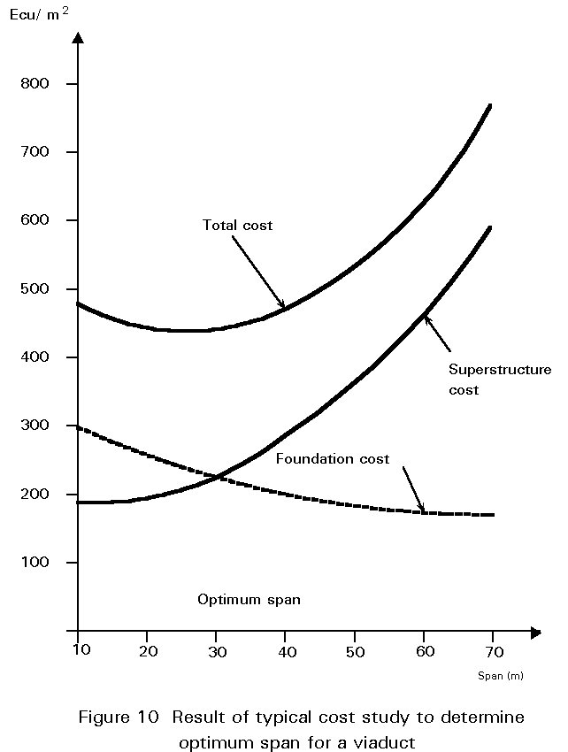
For long viaducts it is worthwhile to carry out initial costed designs for different spans to determine the most economical combination of superstructure and substructure costs. The outcome of a typical study is shown in Figure 10. Typical optimum spans are shown below.
|
Conditions |
Highway |
Railway |
|
Simple foundations (spread footing or short piles) |
25-45 |
20-30 |
|
Difficult foundations (piles 20m long) |
35-55 |
25-40 |
|
Piers 15m high |
45-65 |
30-45 |
Table 2 Typical optimum span ranges for viaducts
SCI P065 Design Guide for Continuous Composite Bridges: 1 Compact Sections, Iles DC, 1989
SCI P066 Design Guide for Continuous Composite Bridges: 2 Non-Compact Sections, Iles DC, 1990
SCI P084 Design Guide for Simply Supported Composite Bridges, Iles DC, 1991
SCI P204 Replacement Steel Bridges for Motorway Widening (SCI in association with BCSA and British Steel General Steels), Iles DC, 1992
SCI P208 Motorway Widening: Steel Bridges for Wider Highway Layouts, Iles DC, 1993.