ESDEP WG 14
STRUCTURAL SYSTEMS: BUILDINGS
To give the designer a deeper understanding of how to analyse a rigid jointed frame structure and to describe the checks to be performed according to Eurocode 3 [1].
Lecture 7.11: Frames
Lecture 14.8: Classification of Multi-Storey Frames
Lecture 14.2: Analysis of Portal Frames: Introduction and Elastic Analysis
Lecture 14.3: Analysis of Portal Frames: Plastic Analysis
Lecture 14.7: Anatomy of Multi-Storey Buildings
Lecture 14.10: Simple Braced, Non-Sway Multi-Storey Buildings
In this lecture the following subjects are treated:
The discussion is closely related to the Eurocode 3 [1] approach to the analysis and design of framed structures.
In this lecture the methods of structural analysis are discussed. Structural analysis provides the internal forces to be used in safety checks.
In the choice of the structural analysis method, different levels characterized by different degrees of accuracy can be obtained.
A very refined degree of analysis, and hence very accurate methods of analysis, are useless in most of the actual cases in which the common simplified assumptions still hold. It is for this reason that most codes do not refer explicitly to the refined methods and instead only advise simple methods of elastic analysis.
Most recent codes, e.g. Eurocode 3 [1], allow the use of all the well established methods of analysis. They therefore allow the analysis of practically all types of structures using different methods of analysis, depending on the available calculation tools.
The approach adopted by the Eurocode 3 [1] is followed in this lecture.
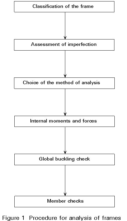
The Eurocode 3 [1] approach to analysis and design requires the following steps:
The procedure is outlined in Figure 1.
For the classification of frames, see Lecture 14.8. This Lecture 14.14 deals with imperfections, the different methods of analysis and the calculation of internal forces and moments.
The global buckling check can be performed by means of exact or approximate methods.
For member checks, see Lectures 7.
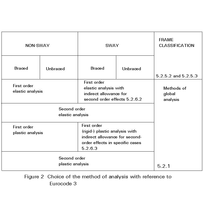
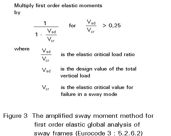
Eurocode 3 allows a first order analysis in the cases outlined in Figure 2, i.e. in non-sway structures as defined in Lecture 14.8 or in sway structures when an indirect amplification is made of the moments. In particular, the indirect amplification can be made by means of the two methods known as the Sway Mode Buckling Length Method or Amplified Sway Moment Method. The procedures for applying the latter method is summarized in Figure 3. See also Section 3.4.4.
In common practice global frame imperfections are not included in the analysis of rigid jointed framed systems. In particular the geometrical imperfections of the frame are not usually taken into account.
Other imperfections, i.e. cross-section and geometrical member imperfections and mechanical imperfections, can be considered part of the knowledge of the steel designer following the extensive research carried out in the 1960's.
Therefore, whilst columns are immediately characterized by initial camber and out-of-straightness and cross-sections are affected by residual stress patterns, it is not yet usually assumed that also the frame is affected by initial out-of-plumb, there is misalignment of the columns and girders and so on, due to erection procedures and fabrication processes.
In common practice the effects of all these imperfections on the frame behaviour are assumed not to be significant and the safety coefficient takes into account the approximations of the analysis which assumes an ideal frame.
As already indicated, it is not common practice to assume global frame imperfections in the analysis. This approach is due partly to the fact that no extensive research has been carried out in this field. Some indications of frame imperfections can be found in the ECCS Recommendations [2], and in [3].
The concept of frame imperfections was introduced in Eurocode 3.
A distinction has to be made between the allowable tolerances which can be accepted for erection purposes and the values which might be included in the analysis of the effects on internal forces and moments.
For frame imperfections, see Figure 4, the Eurocode [1] provides in 5.2.4.2 the method of application at (1) and (2):
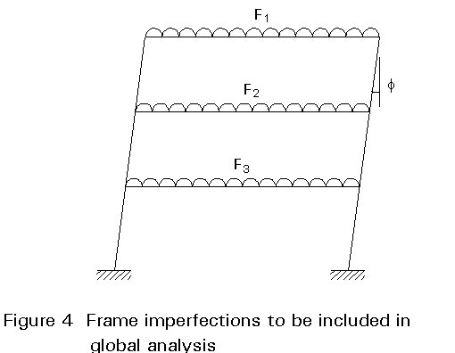
"Imperfections shall be allowed for in the analysis by including appropriate additional quantities, comprising frame imperfections, member imperfections and imperfections for analysis of bracing systems. The effects of the frame imperfections given in 5.2.4.3 shall be included in the global analysis of the structure. The resulting forces and moments shall be used for member design".
Clearly frame imperfections cannot be neglected. The engineer now needs to know their values and how to include them into design. Eurocode 3, at 5.2.4.3: Frame imperfections, provides the following indications on the values to be used:
"The effects of imperfections shall be allowed for in frame analysis by means of an equivalent geometric imperfection in the form of an initial sway imperfection f determined from:
f
= kc ks f0where
f
0 = 1/200 kc = ![]() but kc £ 1,0
but kc £ 1,0
ks = ![]() but ks £ 1,0
but ks £ 1,0
nc is the number of columns per plane
ns is the number of storeys".
Figure 5 shows the initial sway imperfection f for the case nc = 2, i.e. for a one-bay multi-storey frame, together with a curve representing the erection tolerances [3] for the same frame.
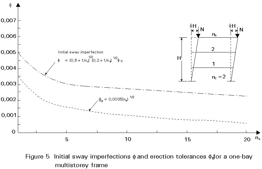
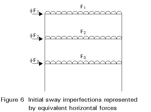
As an alternative to an analysis in which initial sway imperfections are explicitly taken into account, it is allowed to replace these imperfections by equivalent horizontal forces on each floor, see Figure 6.
For more information on imperfections, see Lecture 14.9.
When defining methods of analysis to be used for the calculation of internal forces, it is necessary to make some assumptions for the models to be adopted for the cross-section behaviour and for the material behaviour.
The models can be extremely simple, e.g. elastic analysis which assumes the material, the cross-section and the structure to behave indefinitely in an elastic manner. Alternatively they can be more complicated up to the level of complete simulation of the real in-elastic behaviour of the structure, e.g. elasto-plastic analysis.
The definitions, given below are extracted from the Eurocode 3 [1].
The first important division between the methods of analysis is the one which separates elastic and plastic methods. Whilst elastic methods can be used in all cases, the plastic methods may be used only in the case in which the material and the cross-sections satisfy specific requirements. The different types of plastic analysis are used depending on the assumptions made concerning the material and cross-section behaviour and the specific analytical procedure adopted for simulating the structure behaviour. In particular the most used types of analysis are Rigid-Plastic, Elastic-Perfectly Plastic and Elasto-Plastic methods.
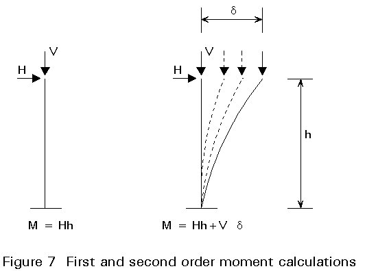
Another important distinction in the methods is between those which make allowance for the effects of deformations and those which neglect these effects. In common practice these methods are also referred to as first order and second order methods (Figure 7). It is clear that second order methods can be adopted in all cases since they do not make any simplification. Therefore they lead to a more accurate evaluation of the internal forces and moments than first order methods. First order methods in comparison have to be used with simplifying assumptions which guarantee that the actions in the structure as derived by the deformed configuration are negligible when compared to the ones computed on the undeformed structure.
For a quantification of these requirements, see Section 3.4.3.
First order elastic global analysis of rigid jointed steel frames can be carried out with the usual methods of structural analysis. The method commonly used is the displacement method which uses the equilibrium equations for the different internal actions in each node. The result is a system of equations where the displacements in each joint are the unknowns. In matrix form the problem is written:
F = kd (1)
where
F are the external actions on the nodes expressed in the global coordinate system
d
are the unknown displacements of the nodes in the global coordinate systemK is the stiffness matrix of the structure obtained by assembling the stiffness matrices of the different bars in the global coordinate system
The solution of the system of equations in the unknown delta gives the global displacements. They enable, through the transfer matrix, the local displacements at each end of the elements to be derived. Hence the internal forces and moments are obtained through the element stiffness matrix.
The stiffness matrix of the single element, written in the local coordinate system in the case of plane frames, is found in standard text books, see Section 7, Reference 6.
For first order elastic global analysis of rigid jointed frames there are no coefficients to take account of relative rotations at the joints and of the change of the flexural stiffness terms due to axial loads.
Since it is a first order elastic method, the solution is a one step process without any need for iteration of the external loads or updating of the matrices.
It is sometimes necessary to take into account that the deformations due to the external loads can considerably modify the structural response and therefore the value of the internal actions.
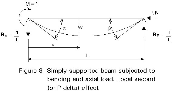
Second order analysis is carried out by using the equilibrium equations for the deformed shape of the structure and the structural elements. In particular, for rigid jointed rectangular frames, the internal actions which cause the most modification of the response are the axial loads. With this assumption, the second order effects can be restricted to local second order effects (first non linearity), commonly referred to as P-delta effects, see e.g. Figure 8, and global second order effects (second non linearity), referred to as P-Delta effects, see e.g. Figure 9.
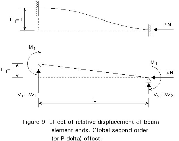
Local second order effects arise in each element subjected to axial load (columns) due to the midspan deflection, whilst global second order effects arise in the frame due to relative displacements between the floors (drifts).
To take into account the local deformation of each element, it is necessary to rewrite the terms of the stiffness matrix of the single element. This is easily obtained if the flexibility coefficients of a simply supported beam under axial loads, where the effects of deformations of the beam itself are taken into account, are known.
To derive the flexibility coefficients, the differential equation of the simply supported beam of Figure 8 is written (see standard text books on applied mechanics:
-EIw" = ![]() (2)
(2)
This equation shows that the bending moment includes also the effects of the axial load.
By imposing the boundary conditions, the values of the flexibility coefficients are:
a
=where:
f
and y are coefficients depending on the parameterkL = L![]() (4)
(4)
kL represents the ratio between the design axial loads in the column and the Euler buckling load obtained assuming no interstorey drift. f and y are found in standard text books.
By adopting these modified flexibility coefficients, usual procedures for constructing the new beam stiffness matrix Ko can be followed.
It is worth noting that, for values of kL less than 0,5, all the coefficients are approximately equal to 1 and therefore there is no need to modify the beam stiffness matrix. For kL = 0 the first order situation appears with the exact values f = y = 1.
To determine how the global frame stiffness matrix is affected by the effects of interstorey drifts in the case of rectangular frames, only some of the stiffness coefficients of the single element have to be reviewed.
From Figure 9 it appears that a relative displacement u1 = 1 between the ends of the beam element leads to a modification of the end shears:
D
V1 = land, thus, to a modification of the matrix of the single element:
ki = k0i (l) - lk1i (5)
where
k0i is the stiffness matrix which takes into account the local deformation of the element, which is relevant also for non-sway frames
k1i is the matrix which takes into account global displacements of nodes.
The global stiffness matrix of the frame, which can be derived by assembling the single stiffness matrices with the usual procedure, has a form similar to matrix (5):
k = K0 (l) - lK1 (6)
To compute the elastic critical load in the exact manner, the determinant of the matrix (6) where Ko is the stiffness matrix of the structure including the P-delta effects and K1, takes into account the P-Delta effects has to be zero. The eigenvalue problem to be solved is:
|K0 (l ) - l K1| = 0 (7)
The different solutions of this equation represent the eigenvalues l and the smaller one represents the elastic critical load of the structure. Several numerical procedures are available in existing computer packages for finding these zeros.
As mentioned earlier in Section 2.3, second order effects can be taken into account approximately by making use of equivalent horizontal forces applied at each storey. The procedure of second order analysis is an iterative one and makes use, in each step, of an elastic analysis.
Equivalent horizontal forces can be applied as suggested by the Eurocode 3 [1] in lieu of the initial sway imperfections, see Figure 6.
This section indicates, by reference to Eurocode 3 [1], strictly related to how to choose the level of elastic analysis of the structural behaviour in order to evaluate the internal forces and moments for the safety check of members.
The internal forces and moments may generally be determined using either first order theory or second order theory in accordance with 5.2.6.2 of Eurocode 3, see Figure 2:
a. non-sway frames
b. sway frames, when design methods which make indirect allowances for second order effects are used
When a first order elastic analysis is used based on the above assumptions, the calculated elastic moments may be redistributed by modifying the moments in any member by up to 15% of the peak moment in that member, provided that:
a. the internal forces and moments in the frame remain in equilibrium with the applied loads
b. all the members in which the moments are reduced have Class 1 or Class 2 sections
The problem of choosing a first or second order elastic analysis can be solved by considering the detailed definitions and explanations given in Lecture 14.9.
The definitions of the different systems (bracing systems and braced frames, sway and non-sway, etc.) are given in Lecture 14.9. Following the choice of a structural system, assumptions are made concerning the structural behaviour. These assumptions have to be verified. At this stage it is important to verify if the structure is a sway or non-sway type. For this purpose the following practical procedure, given in Eurocode 3, 5.2.5.2 [1] as an application rule, can be followed:
"A frame may be classified as non-sway for a given load case if the elastic critical load ratio VSd/Vcr for that load case satisfies the criterion:
VSd/Vcr £ 0,1
where
VSd is the design value of the total vertical load
and
Vcr is the elastic critical value for failure in a sway mode".
The problem is therefore shifted to the evaluation of the elastic critical load. Several procedures can be followed for this purpose:
For simple structures, 5.2.5.2 of Eurocode 3 provides the following application rule for the indirect evaluation of the critical load:
"Beam-and-column type plane frames in building structures with beams connecting each column at each story level may be classified as non-sway for a given load case if the following criterion is satisfied. When first order theory is used, the horizontal displacements in each storey due to the design loads (both horizontal and vertical), plus the initial sway imperfection applied in the form of equivalent horizontal forces, should satisfy the criterion:
![]() £ 0,10
£ 0,10
where
d
is the horizontal displacement at the top of the storey, relative to the bottom of the storeyh is the storey height
H is the total horizontal reaction at the bottom of the storey
V is the total vertical reaction at the bottom the storey".
The simple interpretation of this criterion is that the second order moment equal to Vd is at least ten times less than the first order moment H h, see Figure 7.
As already indicated, a rigid jointed frame can be considered as a non-sway frame when the ratio between the design vertical load Vsd and the critical load Vcr is less than 0,10. When this relation is not satisfied, it is necessary to include second order effects in the analysis. For this purpose Eurocode 3 [1] allows the adoption of the following procedures, see Figure 2:
1a The first method, the most general, consists of checking the safety of elements in buckling and strength on the basis of the internal forces and moments computed with a second order elastic analysis as described in Section 2.3.2. For this purpose the safety check of single elements is carried out assuming values for effective length corresponding to the case of non-sway frames.
1b Alternatively for building structures, the approximate method known as the Equivalent Lateral Force Procedure can be used. This procedure assumes there are no axial deformations in the members and that the second order effects are due only to horizontal displacements. The procedure, which is an iterative one, evaluates the global storey moment, as given by the total axial load times the relative storey drift, and therefore the equivalent lateral forces which then enable a new horizontal displacement to be compared to the previous one. The procedure is stopped when the difference between two subsequent steps is small in terms of additional forces or displacements.
For the strength and buckling safety checks the same considerations hold, as given in paragraph 1a above.
2a In the elastic analysis of sway frames it is possible, as an alternative to second order analysis carried out by following the procedures above, to carry out a first order elastic analysis by means of two different procedures in the safety check of members. The first one is defined as the Amplified Sway Moment Method which can be adopted when Vsd/Vcr is less than 0,25. The approximate evaluation of the second order effects is then based on the amplification of the bending moments associated with the loading conditions which produce lateral displacements of the frame, see Figure 3. The amplification factor for the moments is given by:
C = 1/(1 - Vsd/Vcr )
or, approximately, by:
C = 1/(1 - dV/hH)
The Amplified Sway Moment Method requires the adoption of an effective length for the member buckling checks, equal to the one computed in the case of non-sway frames.
2b A second procedure, which still allows a first order elastic analysis, makes use of the effective length for the columns as computed for sway frames. This procedure is known as the Sway Mode Buckling Length Method. The well-known alignment charts or the Wood diagrams can be used for this purpose, see e.g. [4].
The calculation of internal forces and moments, amplified to take into account sway effects in the different ways described above, is followed by the strength and buckling safety checks on the different members as discussed in other lectures.
There are practically no limitations in choice of the cross-sections. Any class may be used, taking into account the limit on the resistance of cross-sections due to local buckling.
The elastic methods described above enable a solution in terms of displacements from which the strains and therefore the stresses can then be derived.
The classic methods of plastic analysis follow a different logical procedure. They are not concerned with the elastic deformations and the subsequent stresses. Plastic theory, in its first and classical derivation, in fact is only concerned with the derivation of the ultimate resistance of the structure and does not provide any information on the deformations of the structure itself.
The methods which are commonly referred to as rigid plastic methods, and are described in Eurocode 3 [1], are the ones which adopt these assumptions. In fact, Eurocode 3 [1], when referring to "Rigid-Plastic" methods (Clause5.2.1.4(6)), states:
"In Rigid-Plastic analysis, elastic deformations of the members and the foundations are neglected and plastic deformations are assumed to be concentrated at plastic hinge locations".
The main difference between elastic and plastic methods is that whilst elastic analysis is concerned at the same time with equilibrium and compatibility, in plastic methods, only the equilibrium equations have to be satisfied since the structure can overcome the compatibility at different joints by allowing the formation of plastic hinges. It is clear that in some cases the application of the plastic concept is more simple and straightforward. If elastic analysis is used, the compatibility and equilibrium equations at the joints lead to the elastic distribution of internal forces; for plastic analysis, the plastic resistance of the cross-section of each member connected at the same joint immediately allows the ultimate resistance of that joint to be defined as the summation of all the plastic moments. The plastic method is sometimes simpler therefore and provides more information in terms of ultimate resistance which, in the limit state design philosophy, represents an important limit state. The safety of the structure is derived by defining the factored load and the factored resistance. Another advantage of the plastic method is that it is insensitive to geometrical and mechanical imperfections of the cross-sections and the frame since they affect the elastic distribution of stresses but have no effect on ultimate resistance. A disadvantage of the plastic method is however that it cannot provide any information relating to serviceability limit states since it has no concern with elastic deformations and loss of compatibility. It cannot be used alone therefore and has to be complemented with an elastic analysis of the structure for serviceability.
The classical rigid-plastic methods are derived within the following main assumptions and limitations:
In Eurocode 3 [1], to apply this method some requirements are made on the cross-section in order to guarantee that the fully plastic moment can be developed and sufficient rotations are developed within the joints in which plastic hinge locations are formed. Class 1 cross-sections have to be used.
In order to compute the collapse multiplier of external actions, the classic theorems of plastic analysis are usually adopted. The kinematic and static theorems which allow a set of unconservative (kinematic) and a set of conservative multipliers (static) to be defined which includes the collapse multiplier. These well-known theorems are:
Static theorem: If a distribution of bending moments exists throughout a frame which is both safe and statically admissible with a set of loads l, the value of l must be less than or equal to the collapse load factor lc.
Kinematic theorem: For a given frame subjected to a set of loads l , the value of l which corresponds to any assumed mechanism must be either greater than or equal to the collapse load factor lc.
The elastic-perfectly plastic methods are included in the category of plastic methods. They contain some improvements with respect to classical plastic theory and therefore with respect to the rigid-plastic methods.
In particular, 5.2.1.5 of Eurocode 3 [1] states:
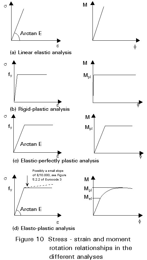
"In Elastic-Perfectly Plastic analysis it is assumed that the cross-section remains fully elastic until the plastic resistance moment is reached and then becomes fully plastic. Plastic deformations are assumed to be concentrated at plastic hinge locations", see Figure 10c.
The hypothesis and limitations are therefore practically the same as those already outlined for the rigid-plastic methods except for the introduction of elastic deformations of the cross-sections which allow not only the global collapse load but also the load-displacement history of the frame to be determined. To enable computation of the plastic rotations at all the joints, a further hypothesis is made that the material and the cross-sections are perfectly plastic, i.e. they can undergo indefinite deformations (rotations).
In practice an elastic-perfectly plastic analysis is carried out by means of a step by step procedure. This method, even though it leads to the non-linear load-displacement curve of the frame, does not need any type of iteration. In fact it is simply made by the contribution of several linear steps each one characterized at its end by the formation of one or more plastic hinges which define the new structure to which further load is applied.
The collapse multiplier obtained using the hypothesis of elastic-perfectly plastic analysis is the same as that obtained under the rigid-plastic hypothesis. This result arises, as indicated earlier, because the value of the multiplier is not affected by elastic redistribution of forces but only by the equilibrium equations. The only reason for adopting a step-by-step analysis to determine the collapse multiplier, is firstly to use a procedure which can easily be introduced in a computer program having a linear package, and secondly that the required rotations in all the sections are given as part of the output.
To apply this method some requirements are given in Eurocode 3 [1] for cross-sections in order to guarantee that the fully plastic moment can be developed and sufficient rotations are developed within the joints in which plastic hinge locations are formed. Class 1 cross-sections are required if no computation is made of the required rotation while at least Class 2 cross-sections have to be applied if they can provide the required rotation.
The elasto-plastic methods remove the hypothesis of elastic-perfectly plastic material. Therefore:
To introduce a generic non-linear moment-rotation relationship in the analysis an iterative procedure has to be followed. In this case, some of the limitations of classic plastic analysis can be removed by making allowance for:
These assumptions can be introduced in a complete non-linear program if an iterative procedure is introduced. In this case the analysis is carried out by imposing small increments of loads or displacements and then by searching through subsequent iterations to obtain the solution which satisfies equilibrium and compatibility in each step within predetermined accuracy. In each step the plastic moment can be adjusted in order to take into account the axial and shear effects. The stiffness matrices of the bar and the entire frame can be updated to take into account the local and global second order effects by means of the procedures specified in Section 3.3.2.
Different well-known procedures can be used to obtain the best convergence of the iteration, i.e Newton, Newton-Raphson, Riks, etc.
Eurocode 3 [1] refers to elasto-plastic analysis in Clause 5.2.1.4(8), as follows:
"In Elasto-Plastic analysis, the bi-linear stress-strain relationship may be used. Alternatively a more precise relationship may be adopted. The cross-section remains fully elastic until the stress in the extreme fibres reaches the yield strength. As the moment continues to increase the section yields gradually as plasticity spreads across the cross-section and plastic deformations extend partially along the member" (see the dashed line in Figure 10d).
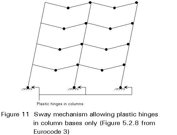
In elasto-plastic zones rather than plastic hinges developing, as shown in Figure 11, failure occurs if a mechanism of fully plastified zones has developed. The number of fully plastified zones depends on the redundancy of the frame.
The elasto-plastic analysis is a method which is not likely to be used by engineers in practice but rather by researchers.
There are no practical limitations in elastic-plastic analysis since the complete non-linear analysis allows all possible effects to be introduced into the simulation of the behaviour of the structure. To apply this method some requirements are given in Eurocode 3 [1] for the cross-sections in order to guarantee that the fully plastic moment can be developed and sufficient rotations are developed within the joints in which plastic hinge locations are formed. Class 1 sections are required if no computation is made of the required rotation while Class 2 cross-sections have to be applied if they can provide the required rotation.
Section 3.4 described the general definitions and procedures for calculating internal forces and moments, that are not only valid for an elastic analysis but also for a global plastic analysis. Some additional requirements for global plastic analysis are given by 5.2.1.4 of Eurocode 3 [1]:
a. when plastic global analysis is used, lateral restraint shall be provided at all plastic hinge locations at which plastic hinge rotation may occur under any load case.
b. when rigid plastic methods are used, sway frames cannot be analyzed except as described in Section 4.4.1 below.
c. when elasto-plastic analysis is carried out, it may be assumed to be sufficient, in the case of building structures, to apply the loads in a series of increments, stopping when the full design load is reached, and to use the resulting internal forces and moments to perform resistance and buckling checks.
d. at the plastic hinge locations, the cross-sections of members containing plastic hinges shall have an axis of symmetry in the plane of loading.
When plastic analysis is used, Eurocode 3 (Clause 5.2.6.3) requires allowance to be made for the second order effects in the sway mode:
"This should generally be done directly by using second order elastic-plastic analysis".
However, as an alternative, rigid-plastic analysis with indirect allowance for second order effects may also be adopted for:
a. frames one to two storeys high, provided that no plastic hinge locations occur in the columns, or else that columns satisfy Clause 5.2.7 of Eurocode 3 [1], Column requirements for plastic analysis;
b. frames with fixed bases, in which the sway failure mode involves plastic hinge locations in the columns at the fixed bases only (Figure 11), and the design is based on an incomplete mechanism in which the columns are designed to remain elastic at the calculated plastic hinge moment.
[1] Eurocode 3: "Design of Steel Structures": ENV 1993-1-1: Part1.1: General Rules and Rules for Buildings, CEN, 1992.
[2] European Convention for Constructional Steelwork, European Recommendations for Steel Construction, Bruxelles, ECCS, (1978) 234.
[3] De Luca, A., Faella, C., Mele, E., Advanced In-elastic Analysis: Numerical Results and Design Guidelines for Rigid and Semi-Rigid Sway Frames, SSRCW Shop in "Plastic Hinge Based Methods for Advanced Analysis and Design of Steel Frames" Pittsburgh, April 1992.
[4] Ballio, G., Mazzolani, F. M., "Theory and Design of Steel Structures". Chapman and Hall, 1983.