ESDEP WG 14
STRUCTURAL SYSTEMS: BUILDINGS
To describe the different functions accommodated by multi-storey buildings and to present the various building elements.
Lectures 1B.7: Introduction to Design of Multi-Storey Buildings
Lecture 3.5: Fabrication/Erection of Buildings
Lecture 4A.3: Practical Corrosion Protection for Buildings
Lecture 4B.4: Practical Ways of Achieving Fire Resistance of Steel Structures
Lecture 14.9: Methods of Analysis for Multi-Storey Frames
Lecture 14.10: Simple Braced Non-Sway Multi-Storey Buildings
Lecture 14.11: Influence of Connections on Behaviour of Frames
Lecture 14.12: Simplified Method for Low-Rise Frames
Lecture 14.13: Design of Multi-Storey Frames with Partial Strength and Semi-Rigid Connections
Lectures 14.15: Tall Building Design
This lecture describes the anatomy of multi-storey buildings.
The range of building types in this category is described.
The anatomy of a typical building is described by considering the individual elements of structure, finishes and services.
Multi-storey steel-framed buildings can accommodate a wide range of functions and architectural treatment.
The term multi-storey refers to structures with more than one storey and covers building used for many different purposes including:
Although the basic anatomy of each building is similar, they may have different requirements for column grid, services, and internal/external finishes.
For example, a car park may be designed with floors of moderate spans and will have minimal requirements for cladding, finishes and services, whereas a prestige office development may need large column free areas with air conditioning and under-floor cabling for computers.
The structure will generally be more economic if large-spans are avoided, hence providing a shorter path between the point of application of loads and the ground.
The speed and economy of construction can also be increased by the large degree of vertical and/or horizontal repetition common in the structural systems of multi-storey buildings.
The individual contributions of major components to the overall building cost can vary significantly with building function, size and architectural treatment. However they are generally within the indicative ranges given below:
|
Foundations |
5% to 10% |
|
Steel Skeleton |
10% to 20% |
|
Floor Structure |
5% to 10% |
|
Cladding/Finishes |
15% to 40% |
|
Services |
15% to 40% |
The structural frame is provided to transmit vertical and horizontal loads from their point of application to the foundations by the most efficient path with the minimum impact on the economy and function of the other elements of the building.
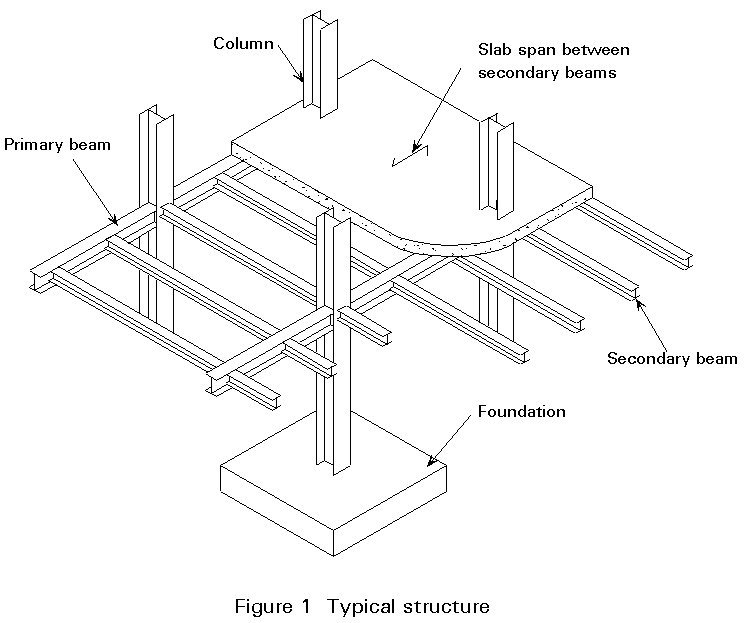
Figure 1 illustrates the principal structural elements of a typical multi-storey building.
The floor slab usually spans one way and is, either simply supported or continuous. It is supported by 'secondary' steel beams, typically at 2,5m to 3,5m centres. Several different types of slab can be used, most of which can be designed to act compositely with the supporting beams if adequate shear connection is provided.
The system illustrated in Figure 2 is commonly used, where a concrete topping (lightweight or dense) is cast in-situ on profiled steel decking acting as permanent formwork and reinforcement to the concrete. Steel bars are included in the slab to prevent cracking and to provide reinforcement in the event of degradation of the decking in a fire.
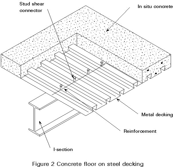
This form of slab construction is particularly popular for multi-storey buildings where rapid construction is required. The demands on cranage are low as many sheets of steel decking may be lifted at a time and the concrete topping may be placed by pump. For spans up to about 3,5m temporary propping may not be required.
The steel decking is available in a number of different profiles, many of which include systems for supporting services below.
The overall weight of this system is low leading to possible economies in the supporting frame and foundations, particularly if lightweight concrete topping is used. It is however relatively expensive and not suitable for situations where a ceiling is not required.
Other types of floor slab construction can offer advantages in certain circumstances where, for example, speed of construction and cranage are not problems, or a larger span is required.
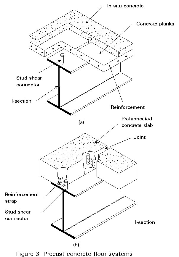
In-situ concrete, cast on temporary formwork, either reinforced or pre-tensioned is suitable for larger two-way spans and where a smooth soffit finish is needed.
Precast concrete units also provide a smooth soffit and some of the different types available are illustrated in Figure 3. These systems require more cranage and on-site storage space than profiled steel sheet, but they can be used for larger spans.
Timber floors are not common in steel buildings.
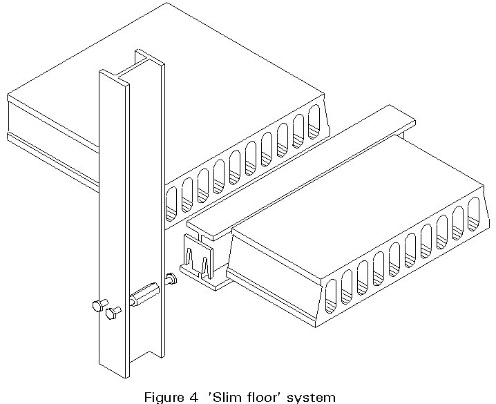
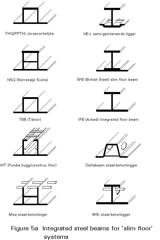
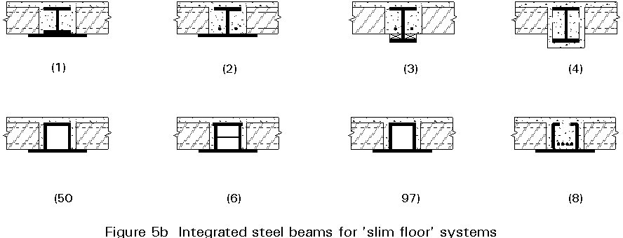
A new floor system, so-called 'Slim Floor', has been developed during the 1980's and early 1990's. It is used for long span slabs, allowing for the elimination of secondary beams (Figure 4). The primary beam has a typical built-up cross-section, which is designed in order to directly support the floor slab on the bottom flange (see Figure 5a). According to the different systems produced in Europe, distribution can be made between open and closed sections (Figure 5b); in particular types 1, 2, 3, 4 are open, single-symmetric I beams, types 5, 6, 7 are closed top-hat beams, type 8 is open top-hat beams.
Steel beams are integrated with in-situ concrete, providing composite action.
Typical dimensions for 'Slim Floor' are the following:
|
Floor (Beam) Depth |
Beam Span |
Slab Span |
|
200 mm |
5 m |
7 m |
|
260 mm |
7 m |
9 m |
The floor slab is normally supported by 'secondary' steel beams, spanning between 'primary' beams which are in turn supported by the columns. Bays of the frame are normally rectangular with the secondary beams spanning the greater dimension. For long-span slab systems the secondary beams are sometimes omitted, as for example in the 'Slim Floor' system illustrated in Figure 4.
Shear studs are welded to the top flange of both primary and secondary beams to provide composite action between the beams and the concrete slab. The slab then acts as the compression flange to the beams for loading applied after the slab has matured. When profiled steel decking is used, the studs are often welded through the decking after it has been placed.
Column spacing depends on building function, but is usually between 5m and 10m. Closer centred columns may be used in an external 'tube' stability system for a tall building as described later (see Section 2.2.3).
The simplest and hence normally most economic system, is for both primary and secondary beams to be rolled I-sections in the same horizontal plane, designed as simply-supported, and with simple bolted connections between them and to the columns.
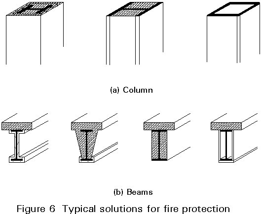
The steel skeleton must be protected against fire. Typical solutions of protection are shown in Figure 6. Columns filled with cast concrete can be designed for composite action (Figure 6a). Beams can be protected in different ways (Figure 6b): by sprayed vermiculite, by concrete encasement, by filled concrete or by box-shaped cladding.
In most buildings, the need to accommodate services has a major effect on the design of the floor system. In an office building, the office floor areas may have air-conditioning ducting, pipes for fire sprinklers, and cabling for electrics, telephones and computers distributed horizontally above and/or below the floor from risers in service cores. The major services are normally under-floor in zones up to 500mm deep, with electric and communication services above within raised floor zones up to 200mm deep. The cores may also house toilets, lifts and stairs, with their requirements for water, sewerage and ventilation.
In most cases it is possible to provide separate service zones below and/or above the floor structure. Buildings with large spans and/or restrictions on storey height will require a different design approach.
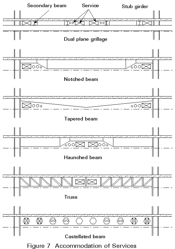
Holes may have to be cut in webs of the beams to accommodate services, a costly operation, or one of the systems illustrated in Figure 7 may be adopted:
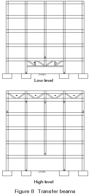
It may not be possible to maintain uniform column spacing at all levels of the building. For example, column-free space may be required at ground floor for a conference area. 'Transfer' beams or trusses can be provided to transmit the loads from above to adjacent columns. They may alternatively be at a higher level, with floors below suspended from hangers (Figure 8).
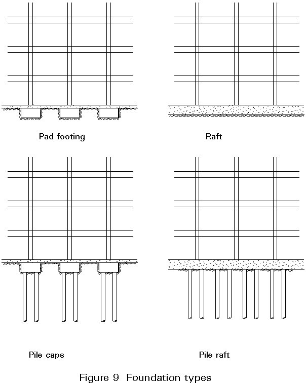
The columns are supported at their base by foundations. Several different foundation types can be used to support multi-storey buildings, the selection for a particular case being dependent on column load, soil resistance and settlement limitations.
The most common types of foundations, illustrated in Figure 9, are:
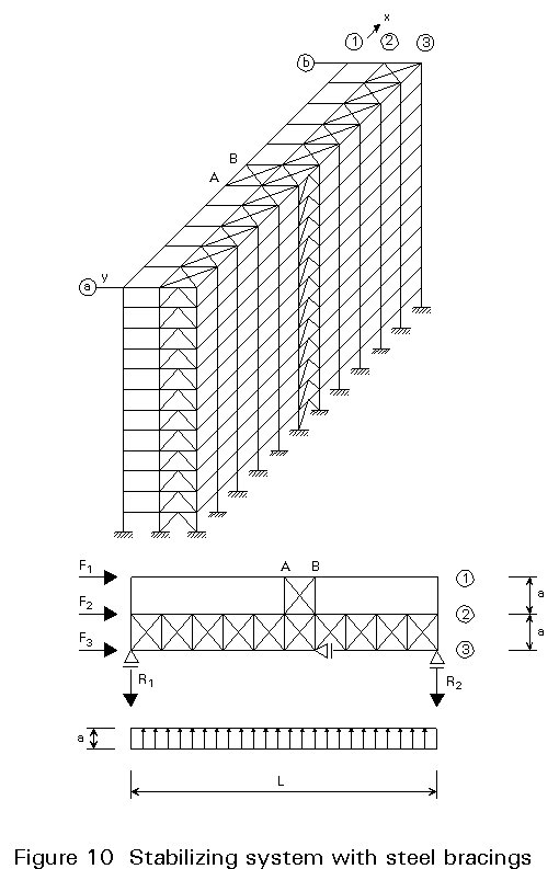
Although the primary function of the structure is to support vertical loads, it must incorporate a lateral stability system to resist horizontal forces, which commonly are wind loads and, in some countries, earthquakes.
Some typical systems are illustrated in Figures 10 and 11, where steel bracings and reinforced concrete cores are used as stabilizing elements, respectively.
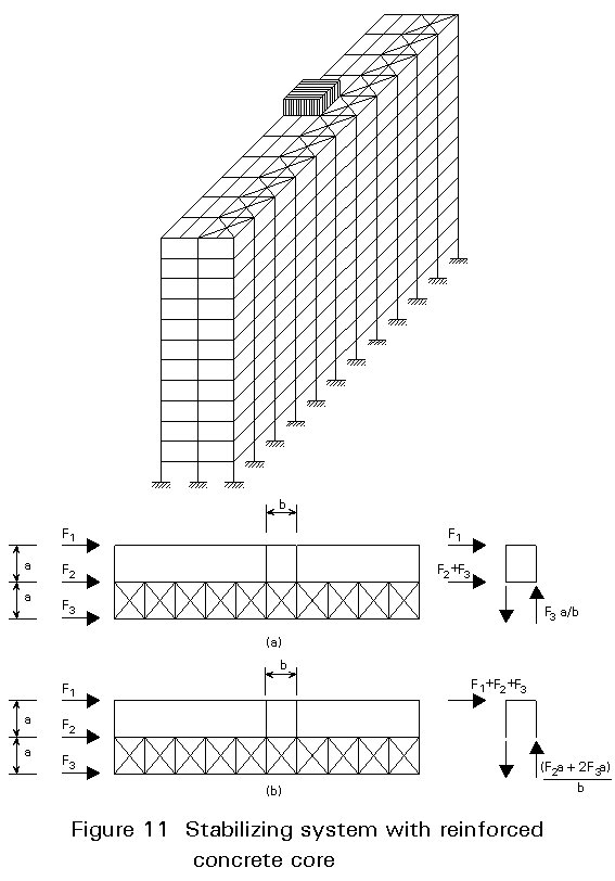
Staircases and lifts (provided for access and escape), toilets, plant rooms and risers for heating, air-conditioning, electrical and public health services, each require penetrations through, and support from, the floor structure of the building. They are usually located together to form one or more 'service cores'.
The resulting walls, required for compartmentation and fire separation, may be used to as the lateral stability elements of the structure. Possible forms of construction include:
Concrete walls can lead to longer construction periods, unless systems such as slip-forming are adopted which allow the core construction to proceed in advance of the erection of the steel frame. Steel to concrete connections can lead to problems if cast-in fixings are out of tolerance.
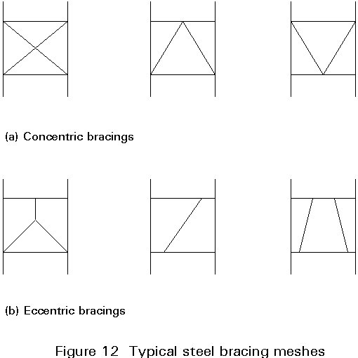
Braced steel frames which are erected at the same time as the other elements of the frame, are most commonly used. Bracing geometry is normally concentric (see Figure 12), allowing the use of simple connections. Eccentric bracing requiring bending resistance in the sections and joints may sometimes be used, however, to allow for increased openings. They can also provide major ductility, when required for seismic resistant structures.
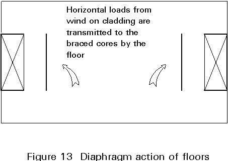
All stability systems use the floor plate as a diaphragm to transfer lateral loads from their point of application to the bracing elements, as illustrated in Figure 13. The designer should ensure that the floor is capable of performing this function.
The bracing system must ensure lateral stability in two main directions and also torsional stability. The correct location of such elements is a fundamental pre-requisite in the bracing system design (see Figure 14).
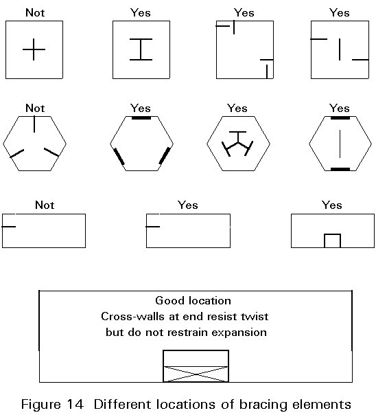
For long floors without expansion joints, the designer should avoid longitudinal walls at both ends of the building, as they will restrict thermal movements, and hence attract large forces.
Bracing systems provide the most economical solution for medium rise multi-storey buildings (see Section 2.2.2).
Alternatively, stability can be provided by moment resisting frames formed by some or all of the columns and intersecting floor beams, as illustrated in Figure 15.
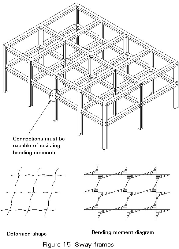
These systems, which may be designed as either 'Rigid' or 'Semi-rigid' frames, which can sometimes offer advantages in terms of increased flexibility of internal layout, are described in detail in Lectures 14.13 and 14.14.
Some examples of stability systems used for tall buildings are illustrated in Figure 16.
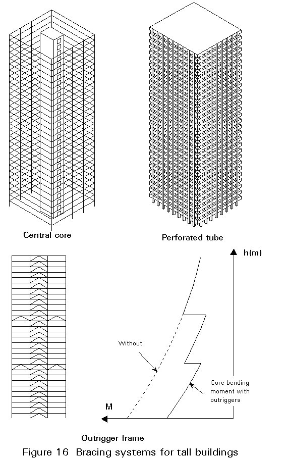
A combination of core and frame systems is common. Advantage can be taken of closely-spaced external mullions framed by relatively deep spandrels between windows acting together to form a 'Perforated Tube'.
'Outrigger Frames', where the central core is connected at one or more levels to the external columns with deep trusses may also be used. The diagram of Figure 16 illustrates how the bending moment in the core is reduced when this system is adopted. Further discussion on tall building design is included in Lecture 14.15.
Figure 17 shows a section through a typical floor deck. The surface treatment applied to the concrete slab will depend on the flooring system required.
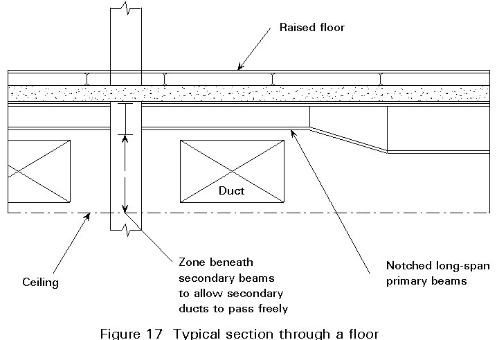
Power floating provides a smooth finish ready for carpets or tiles. A trowelled finish is suitable if a raised floor is to be installed to accommodate electrical and computer services. The surface is tamped to provide a key if a concrete screed is to be applied.
A false ceiling can conceal air-conditioning duct-work and other services suspended from the floor.
Staircase flights and half landings are normally prefabricated in steel or precast concrete for economy and ease of construction, but they may also be constructed of reinforced concrete.
Toilet modules may also be prefabricated and supplied to site in an enclosure complete with all fixtures, fittings, services and finishes.
A variety of external finishes may be used. Common facade treatments which may be supported by the steel frame include:
The chosen cladding system must perform a number of different functions for each building type. For a car park it must be robust and provide natural ventilation, whereas, in an office building, it must be water-tight and provide adequate insulation and natural light without excessive solar gain. For tall buildings it must be able to be installed and maintained without the need for scaffolding. In all cases, it must be capable of accommodating the movements of the building frame and of satisfying the aesthetic requirements of the architecture.
Roofs may be flat or sloping, and clad with a variety of materials to provide insulation and waterproofing.
All elements of the structure should be designed by considering the ultimate and serviceability limit states at which they would become unfit for their intended use. Limit states are considered in Lecture 14.9.
× Cost of construction
× Speed of construction
× Interference with services
× Maintenance costs
× Architecture.
[1] Hart, F., Henn, W. and Sontag, H.: "Multi-Storey Building in Steel" (second edition), Collins, London, 1982.