ESDEP WG 4B
PROTECTION: FIRE
To survey the practical means of achieving fire resistance of steel structures with examples of their application. To describe the essentials of European fire resistance design.
Lecture 4B.1: Introduction to Fire Safety
Lecture 4B2: Background to Thermal Analysis
Lecture 4B3: Background to Structural (Mechanical Fire) Analysis
Lecture 4B5: Calculation Examples
The mechanical properties of all common building materials decrease with elevation of temperature. Steel structural elements should possess an appropriate fire resistance to resist collapse, flame penetration or excessive temperature rise on the unexposed faces. The inherent fire resistance of unprotected steelwork is introduced and the influence of a variety of insulating systems, of partial member exposure and of composite action are discussed. Reference is also made to the effects of water cooling on temperature control.
The mechanical properties of all common building materials decrease with elevation of temperature. Structural elements should possess an appropriate fire resistance to resist collapse; in addition fire resisting partitioning walls and slabs should resist flame penetration or excessive temperature rise on their unexposed faces in order to contain the fire in its original location. The fire stability of a structure is especially important and any failure of the structure in the fire zone should be gradual, involving large plastic type deformations. The parts of the building away from the fire should remain intact.
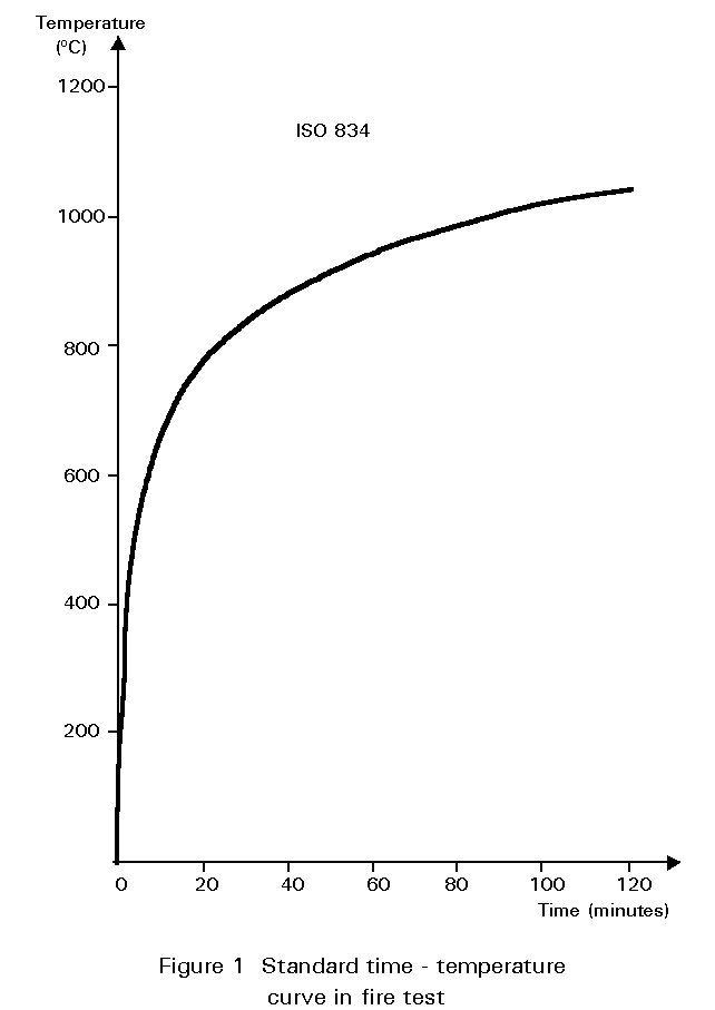
Fire resistance requirements are fixed by National Codes in terms of the time an isolated element should resist the action of a Standard Fire as defined by the heat exposure given by ISO834, (Figure 1). Fire resistance times of 15/30/60/90/180 and 240 minutes are specified depending upon the number of storeys; these times can also be a function of the occupancy of the building and of the fire load.
Steel members will collapse in a fire when their temperature reaches a "critical" level. This critical temperature varies according to the load conditions, the cold design theory adopted and the temperature distribution across the section, which typically is in the range 500 to 900°C.
The fire resistance time is the time, in the standard ISO834 fire test, taken by the member to reach the critical temperature. This time varies according to the section size. In a building in which a natural fire occurs the heating rate is also influenced by the member location. The thicker the steel the slower is the heating rate and therefore the greater is the fire resistance time.
The heating rate is quantified by the Section Factor, known as the Am /A ratio, where Am is the perimeter of the steel member exposed to the fire, and A is the total cross-sectional area of the section. Consequently, a heavy member with a low Am /A ratio will be heated more slowly than a light member with high value of the section factor. Tables are published giving values of section factors for standard section sizes.
For a member to fulfil a given fire resistance requirement, it is necessary to ensure that the temperature developed in the member at the required fire resistance time (taking into account its Section Factor and any insulation which may be applied) is less than the critical temperature necessary to cause failure (also known as the "critical temperature").
For short periods of fire resistance (15, 30 minutes) stability may be attained by unprotected steelwork. A fire resistance time of 60 minutes may sometimes be obtained without applying fire protection by utilising the thermal and/or structural interaction between steel and concrete. For longer periods of fire resistance time, the steelwork can be protected by applying an insulating material, by using screens, or, in the case of hollow sections, by the recirculation of water. Composite steel-concrete structures can also exhibit significant fire resistance.
A brief survey of the simpler practical means of achieving structural fire resistance in steel structures is presented. It is important to recognise, however, that considerable research and development work (fuel loads based on natural fires) is being undertaken in Europe. This work aims to optimise the process of the fire resistant design of structural steelwork leading to further economies in construction.
Bare steel structures may satisfy fire resistance times of 30 and 60 minutes if one or more of the following conditions are met:
Figure 2 shows an example in which the fire resistance of bare steel beams is given as a function of the section factor, for different values of the ratio between the actual load and the collapse load under room temperature conditions.
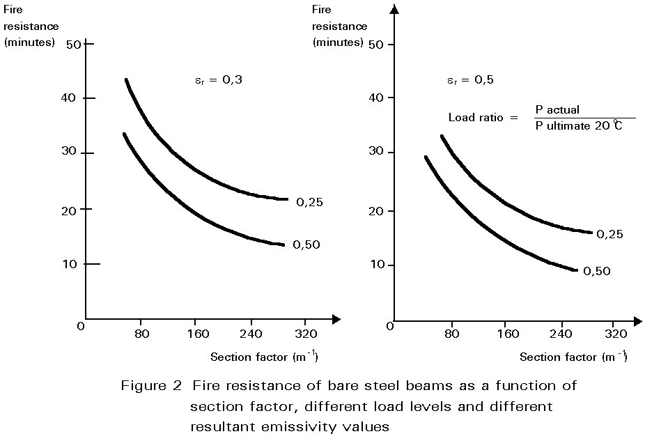
When the ratio between the applied load and the collapse load is reduced, the failure temperature, and thus the fire resistance time, is increased. The fire resistance time can therefore be increased by oversizing the members, by maintaining the member size but using a higher strength steel, by utilising the restraining effects of connections, or by a combination of these methods.
Heating rates of fire exposed members may be calculated on the basis of European Recommendations [1, 2] which are incorporated in Eurocode 3[3]. These rates hold for continuous beams. The calculations assume a uniform temperature distribution across the steel member. However, research has shown that the temperature profile has an important influence on fire resistance when non-uniform temperature distributions are developed. For example, in a beam supporting a concrete slab, the fire resistance is increased due to the transfer of load from the hotter to the cooler part of the section. This effect is accounted for by use of a modification factor 'k' in the calculation method.
In a fire, heat is transferred to the steelwork predominantly by radiation and the rate of heat transfer is described by the resultant emissivity er. The value of er will change according to the characteristics of the furnace used for standard fire tests on beams and their position in relation to the flames. Typically, er will be between 0,3 and 0,5, the lower value resulting in an increase in the measured fire resistance time. The effect of this variation on the fire resistance of bare steel beams is shown in Figure 2.
The fire resistance of bare steel columns exposed to heat on four sides also depends on the section factor and the applied load. Bare columns with section factors up to 30 m-1 have a fire resistance of 30 minutes when working at full design loading, based on Eurocode 3 [3].
In many steel framed buildings, structural fire protection is required to meet the requirement of legislation and to prevent failures of major building components in fires. A wide range of fire protection systems are available. The generic forms, such as concrete, brickwork and plasterboard are well established. The materials available also include sprayed materials, dry products in the form of boards and batts, intumescent products which form a carbonaceous char when exposed to heat, and compounds which absorb heat and undergo chemical changes in fire.
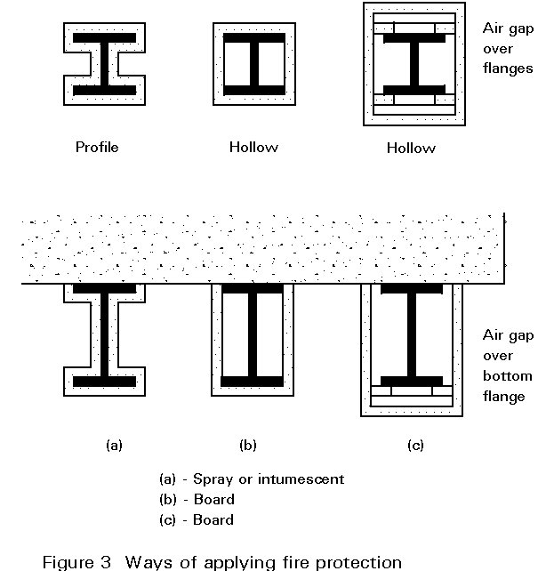
The thickness of the insulation must be such that the temperature of the steel at the required fire resistance time (taking into account its section factor) does not exceed the critical (or limiting) temperature. Government agencies and approved private laboratories have established programmes of fire tests for passive and intumescent protection systems on loaded and unloaded specimens. These tests are designed to determine both the insulation characteristics of a fire protection material and its physical performance under fire conditions for a range of steel sizes. Analytical methods from which reliable assessments of the thickness of the protection medium can be made are now available. The fire protection can be applied to the structural steel member in a variety of ways, as shown in Figure 3.
Sprayed Protection
The various spray systems include mineral fibre products, vermiculite-based products which include either cement or gypsum, perlite/cement products and chemical compounds that absorb heat, such as magnesium oxychloride. The majority of these systems form a slurry in a mixer which is pumped through the nozzle onto the steel substrate. The mineral fibre/cement mixture is mixed with a water spray at the nozzle head. The thicknesses of these materials vary from 10 to 100 mm with specific mass in the range of 200 kg/m3 to 1000 kg/m3.
To achieve the required degree of fire resistance, it is important that the specified thickness of coating is applied. Inspection of the quality of the coating and thickness checking is therefore required. However, no specific guidance is currently available on the number of positions where thicknesses should be checked and the acceptable tolerance limits.
These sprayed materials have several advantages. They are fast to apply, inexpensive and can be adapted to cover complicated shapes including the voids between metal deck floors and steel beams. Their disadvantages are that they are messy, can cause damage due to overspray and are sometimes susceptible to cracking and shrinkage. They do not provide an attractive surface finish unless trowelled smooth.
These systems of protection are generally applied to hidden elements, e.g. beams above suspended ceilings. It may be possible with the aid of colouring to integrate these coatings to the architectural aspect of the structure. The spray composition must be compatible with the substrate, be it primed or unprimed steelwork.
The abrasion and impact resistance of sprayed insulation is improved with an increase in its cohesive strength and density. The coatings are difficult to repair and therefore it is important that any attachments to the steelwork are made prior to the installation of the fire protection.
Dry Systems
These include board systems based on mineral fibre or vermiculite, mineral fibre batts and ceramic fibre blankets. Board materials can either be glued in place using noggings, or screwed to a framework or to other boards. The specific mass of the board materials vary between 165 to 800 kg/m3.
These products are generally easy to use. The extent of checking required during installation is much less than that needed with a spray-applied coating as the products are manufactured with reliable thicknesses. They provide some degree of flexibility in programming, are clean, cause little damage to surrounding constructions and offer a good surface finish. Some board products are soft or brittle and are susceptible to mechanical damage; others are susceptible to water damage and are only suitable for internal use. Installation is not easily adaptable around complex shapes. Few problems are encountered by compatibility with substrates.
Recent developments have seen an increase in the use of mineral fibre batt materials. These materials have a specific mass around 100 kg/m3 and are held in place using pins, welded at regular intervals onto the steel surface, and retaining washers.
The desirable properties of both the spray and dry systems of protection are as follows:
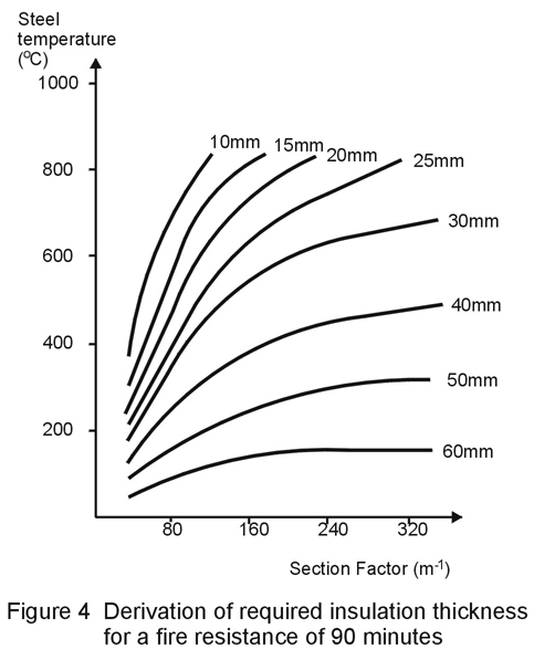
In order to facilitate the use of sprayed and sheet materials, special graphs have been prepared by authorised fire testing laboratories. These graphs give the thickness of a specific material as a function of the section factor, the critical temperature of the structural member, and the required fire resistance period, as shown in Figure 4.
Intumescent Systems
These materials are used to provide a decorative finish to a structure. A range of thin film coatings are available that can satisfy up to 90 minutes fire resistance. These products are mainly suitable of internal use. A range of thick film coatings based upon the epoxy chemicals can satisfy up to 120 minutes fire resistance. These coatings exhibit satisfactory ageing characteristics when used externally.
Typical Intumescent Coating Thicknesses Used on I-Sections
|
Coating type |
Range of basecoat thickness for different fire resistance periods* (mm) |
|||
|
30 mins |
60 mins |
90 mins |
120 mins |
|
|
Solvent based thin coats |
0,25 - 1,0 |
0,75 - 2,5 |
1,50 - 2,50 |
- |
|
Epoxy resin- based thick coats |
4,0 - 5,0 |
4,0 - 11,0 |
6,0 - 16,5 |
6,0 - 16,5 |
*
Data from UK practiceThe thin film coatings or mastics foam and swell under the influence of heat to produce an insulating char layer up to 50 times thicker than the original film thickness. These products can be applied by spray, brush or roller. In order to apply thicker coats multiple treatments are necessary. Control measurements on thickness are required using proprietary measuring equipment which has been developed for assessing paint thickness. Only a limited amount of investigation of durability has been conducted on the ability of certain products to be used externally. Most of the products have good resistance to impact and abrasion.
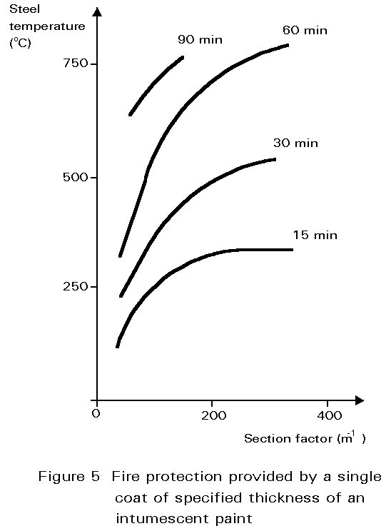
A simplified graph showing fire resistance periods provided by a single coat of intumescent paint is shown in Figure 5.
Tests have shown the need to evaluate the performance of intumescent coatings over a variety of shapes and orientations of the substrate. In the long term it is anticipated that this form of fire protection may be installed by the steel fabricator.
Although these materials have resistance to impact and abrasion, mechanical damage can occur, particularly on columns, requiring maintenance of the paint system to be carried out.
Specification of Fire Protection Thickness
In Eurocode 3: Part 1.2 [3] an equation is given to calculate the rise in temperature of protected steelwork. The thermal conductivity of the insulation material, li, and its thickness di are taken into account as li /di. The heat capacity of the insulation is also included. The thermal conductivity of insulating materials changes with their mean temperature. This change can be taken into account in more precise calculations.
However, if no detailed information is available and if only an approximate answer is required, the analysis may be based on average values of li, which are assumed to be valid for the whole temperature range during a fire. It may be shown that under such circumstances the time to attain a certain steel temperature is governed by the factor
li Am / di A
The required thickness of insulation for a structural steel member may be determined by using a nomogram which relates critical temperature, applied load, section factor and fire resistance. For example, consider an IPE 500 beam supporting an actual load/collapse load, h = 0,625 requiring a fire resistance of 120 minutes and exposed to heat on 3 sides. The nomogram for protected steel is reproduced in Figure 6 for a simply supported beam supporting a concrete slab (k factor of 0,7). The product of h x k = 0,625 x 0,7 = 0,438 and the section factor, Am /A = 132 m-1, for a beam exposed to heat on three sides.
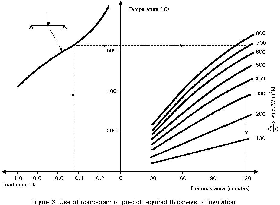
From the nomogram the value of the factor {li Am / di A} is 690 W/(m3.K) to satisfy 120 min fire resistance with h x k = 0,438
![]() (1)
(1)
Values of thermal conductivity, li, may be obtained from manufacturers' data and examples are given in the nomogram. For instance, when li = 0,1 W/m°C (typical of many protection materials), the required thickness of insulation, di ³ 0,1 x 0,19 = 19 mm.
The use of composite steel/concrete components in buildings is becoming increasingly important in fire resistant design because they offer several choices for influencing the rise in temperature of the steel [4, 5]. One is the position and mass of the concrete and a second option is the possibility of redistributing the internal stresses to protected and cooler parts of the section.
Concrete-Filled Hollow Steel Columns
The cross-section of this type of column is either rectangular or circular as shown in Figure 7(a, b, c). The performance in fire depends mainly on the member size and the tensile and flexural properties of the concrete. If non-reinforced concrete is used the fire resistance is normally 30 minutes (Figure 7a). However, a rating of 120 minutes can be achieved by the inclusion of reinforcing bars or steel-fibre reinforcement (Figure 7b).
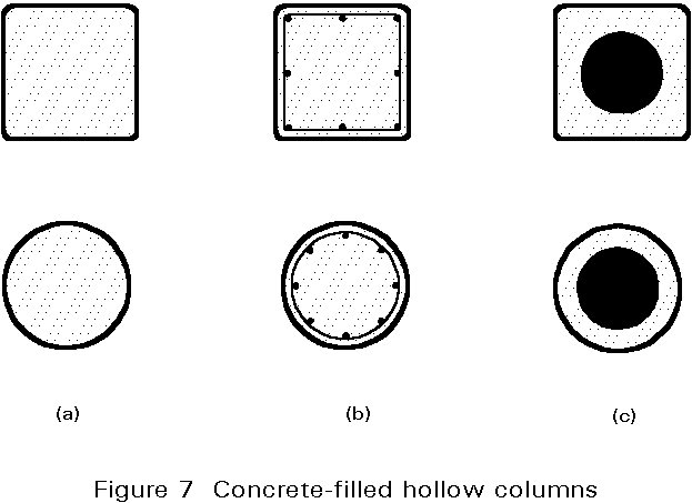
The steel core column (Figure 7c) is a further development of the concrete filled hollow section but with the main part of the load-carrying steel cross-section protected against fire by layers of concrete. The fire resistance of this type of column varies from 60 minutes to higher values depending upon the thickness of the concrete layer. These columns are used as centrally loaded members with small load eccentricities.
Rolled Steel Sections Encased in Concrete
Different types of composite construction utilising steel sections are manufactured into fire resistant columns and beams.
One of the great advantages of composite columns is their uniform outside dimensions in multi-storey buildings. By varying the thickness of the steel section, the material qualities of both steel and concrete, and the percentage of reinforcement, the cross-section of the column may be adapted to support an increased load without significant changes in the outer dimensions. Each type of composite column has specific advantages and ranges of application.
The oldest type of composite column, Figure 8a, is the steel section encased in concrete. Its advantages are a high allowable load level in fire conditions and a high load-carrying resistance not only for centrally applied loads, but also for bending moments. The fire resistance is normally 90 minutes or more.
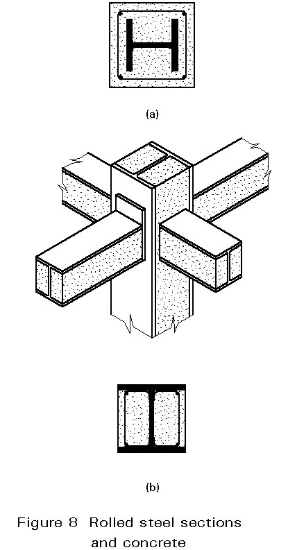
The second type, namely the steel section with concrete between the flanges, can support considerable central loads and high bending moments. The amount of shuttering is significantly reduced. Other advantages are a good resistance to mechanical damage without the need for corner reinforcement and the ability to use conventional steel connections between the columns and steel beams similarly concreted and reinforced between the flanges, as shown in Figure 8b. Such composite sections may reach any desired fire resistance level.
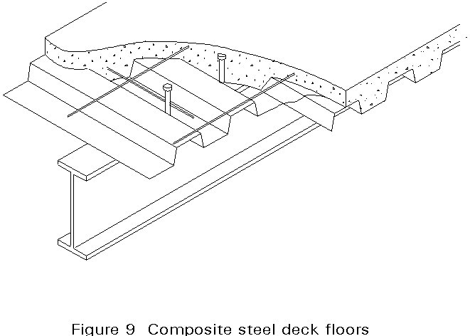
Composite Steel Deck Floors
Composite floors utilising profiled steel decks are very frequently used in building as shown in Figure 9. These floors can have a fire resistance of up to four hours without any fire protection applied to the soffit. Floors with minimal reinforcement have at least 30 minutes fire resistance and a single layer of reinforcement can give up to two hours fire resistance. For longer periods of fire resistance for floors with high loading and long spans, additional reinforcement may be necessary.
Members partially exposed because they are embedded in walls, floors or other elements of structure achieve a significant fire resistance by redistribution of stress from hot exposed regions to cooler (non-exposed) areas of the section. This effect occurs whether there is composite interaction or not. Research and analysis are in progress to quantify this effect.
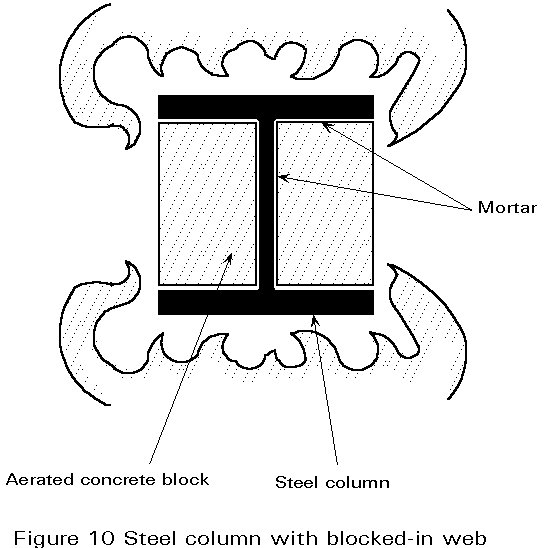
A relatively inexpensive method of improving the fire resistance of free-standing universal columns without the specialist application of fire protection can be achieved by blocking in the volume between the flange and web with non-load bearing conventional lightweight building blocks, as illustrated in Figure 10. Fire tests have demonstrated that universal column sections from 203 mm x 203 mm x 52 kg/m upwards achieve in excess of 30 minutes fire resistance under full design loading.
Another particular example is the shelf angle floor beam illustrated in Figure 11. The time taken for a steel beam to reach its limiting temperature in a fire can be extended by protecting the beam from direct attack by the flames. One economic method of providing this protection is by means of the shelf angle floor design where precast concrete floor slabs rest on steel angles attached to the web of the beam so shielding the upper flange and part of the web from the fire. The resulting decrease in heating rate of the upper part of the beam significantly extends the fire resistance time of the steel beam.
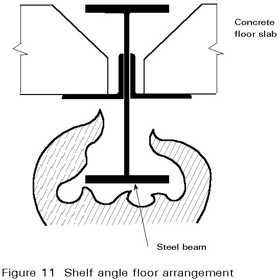
Research results indicate that by selecting suitable combinations of steel beam size and depth of concrete floor unit, fire resistance periods of 30, 60 and 90 minutes are possible without the need for applied lightweight fire protection.
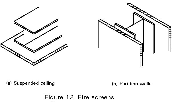
It is not necessary to apply protection to each member in the steel frame of a building before it is completed. When suspended ceilings or partition walls (Figure 12) are used they can offer cost advantages by combining their normal functions with fire protection. The screens must be able to ensure the integrity, insulation and stability necessary to prevent the fire from spreading into the void. Special attention should be paid to the method of assembly and in particular the joints and connections. Any desired fire resistance level can be obtained.
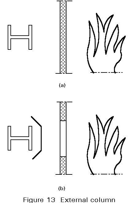
Columns positioned outside a building remain cooler during a fire than those positioned inside. In this way fire stabilities much greater than 30 minutes can be achieved. Existing calculation methods for the mechanical behaviour of such loaded elements in fire have led to the following recommendations:
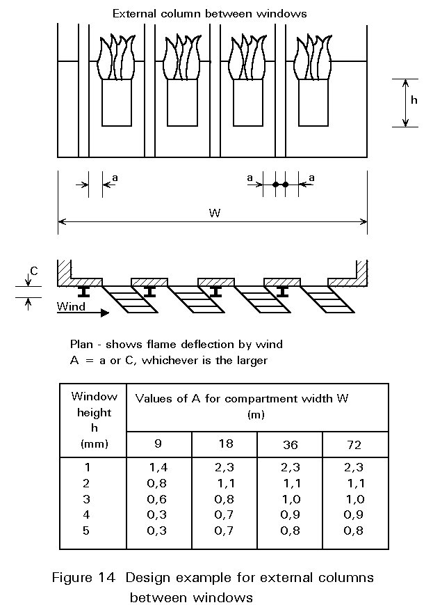
A simplified design example is given in Figure 14. The position of the external columns to avoid excessive rise in temperature is indicated for a building which has all the windows on one wall and no through draught.
The fire resistance of tubular members can be improved by utilising the hollow interior to cool the load-bearing steelwork. Filling such members with water gives extremely high fire resistance when circulation is maintained, Figure 15.
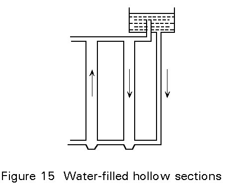
Circulation can be achieved by natural convection using a number of interconnecting members (not all of them fire exposed) with an adequate high level storage tank, by direct connection to water mains and drainage, or by pumps. Research is currently being carried out into static unreplenished systems. Chemicals are added to the water to inhibit corrosion (Potassium Nitrate) and freezing (Potassium Carbonate). With any system, although the water temperature can exceed 100°C depending on the pressure, the steel will remain below its critical temperature.
The outward appearance of the steelwork is unaffected which has advantage architecturally. The design is, however, complex and the method expensive. It is normally confined to prestige buildings or structures requiring extreme levels of fire resistance.
Standard rolled beam and column sections may be cooled by water spray. The procedure is activated as soon as the ambient temperature exceeds a predetermined value. The water flow produced by a number of sprinklers must be in a continuous film over the entire length of the member.
[1] Design Manual on the European Recommendations for the Fire Safety of Steel Structures. ECCS-TC-3 - Brochure No. 35, European Convention for Constructional Steelwork, Brussels, 1985.
[2] European Recommendations for the Fire Safety of Steel Structures: Calculation of the Fire Resistance of Load Bearing Elements and Structural Assemblies exposed to the Standard Fire. ECCS TC 3, Brochure No. 30. Elsevier Scientific Publishing company, Amsterdam, 1983.
[3] Eurocode 3: "Design of Steel Structures": ENV 1993-1-1: Part 1: General rules and rules for buildings, CEN, 1992. Part 10: Structural fire design (in preparation).
[4] Eurocode 4: "Design of Composite Steel and Concrete Structures": prENV 1994-1-1: Part 1.1: General rules and rules for buildings. Part 10: Structural fire design (in preparation).