ESDEP WG 4B
PROTECTION: FIRE
To introduce a basic background of thermal analysis for fire situations.
Basic knowledge of thermodynamics
Lecture 4B.1: Introduction to Fire Safety
Lecture 4B.3: Background to Structural (Mechanical Fire) Analysis
Lecture 4B.4: Practical Ways of Achieving Fire Resistance of Steel Structures
Lecture 4B.5: Calculation Examples
Thermal models are presented and simple rules are given for calculating the transient thermal response of steel elements, with or without a protective coating. The concept of the section factor of the steel section is introduced. Composite steel-concrete elements (columns and slabs) are also discussed.
Fire is a very complex phenomenon which can take many forms and involves different kinds of chemical reactions.
From a structural point of view, only the fires that can cause structural damage are of interest and, in this case, fire can be regarded as an accidental situation.
Design criteria for structural fire safety require some assumptions both for the structural and heating models.
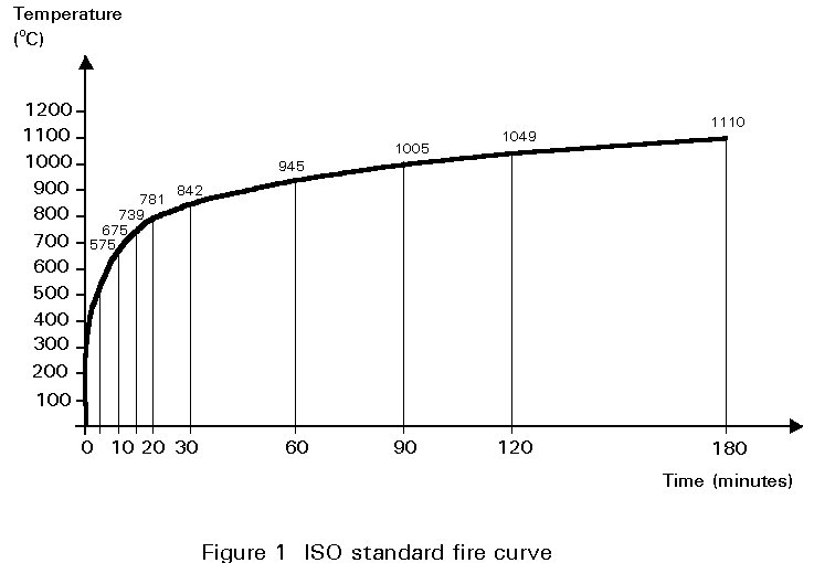
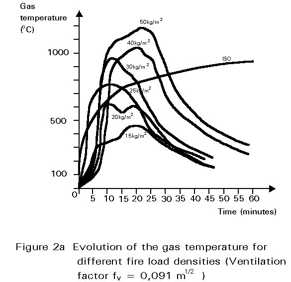
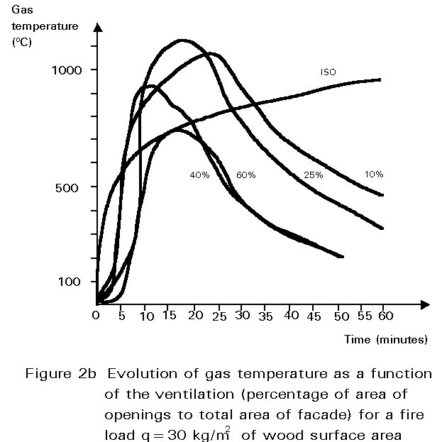
Fire is usually represented by a temperature-time curve which gives the average temperature reached during fire in a small size compartment or in the furnaces used for fire resistance tests. International standards are based on the standard fire defined by the heat exposure given by the ISO 834 curve (Figure 1). In some cases reference can be made to natural fires which have different temperature-time relationships depending on fire load density and ventilation conditions (Figures 2a and 2b).
In more complex analyses different heating models can be considered to represent the temperature development in different zones of the fire compartment or in the neighbourhood of it. This is the case, for instance, for many large industrial buildings or for external columns near to the windows of a building.
The response of a structural member exposed to fire is governed by the rate that it is heated because the mechanical properties of materials decrease as temperature rises and, likewise, the structural resistance of a member reduces with temperature rise.
Collapse occurs at the time when the structural resistance reduces to the applied action effects. This fire resistance time can happen in a very short time when the increase of temperature is rapid. Steel elements have an unfavourable behaviour in this respect due to the very high thermal conductivity of the steel. A rapid heating of the whole profile takes place as a result. In comparison, composite elements have a favourable behaviour due to the great thermal inertia of the elements and the low thermal conductivity of the concrete.
In this lecture some basic aspects of thermal analysis are discussed. The general equation for heat transfer is presented, followed by the simplified method which may be adopted for steel members. Thermal gradients across the section and along the member are neglected.
In a fire, the temperature of the steel increases similarly but with some delay compared to the gas temperature of the fire (Figure 3). The delay depends on the thermal inertia of the element as well as on the intensity of heat flow passing through its external surface. If the element has an applied protective coating, this delay is longer. For bare elements the delay depends on the section factor of the element.
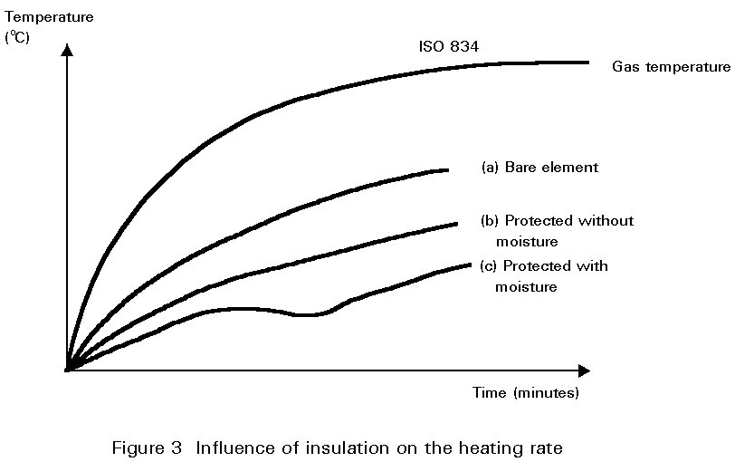
In Figure 3, the temperature rise in three different cases is compared for the same element. Curve (a) represents the delay for the bare element, while curves (b) and (c) apply to the cases of some protective coating, without and with moisture content.
The rise of temperature in a structural steel member depends on the heat transfer between the fire environment and the element.
According to the second law of thermodynamics, energy in the form of heat is transferred between any two elements which are at different temperatures. Conduction, radiation and convection are the modes by which thermal energy flows from regions of high temperature to those of low temperature.
On the external surface of building elements all three mechanisms are present. Inside the elements, heat is transferred from point to point only by conduction.
The general approach to studying the increase of temperature in structural elements exposed to fire is based on the integration of the Fourier heat transfer equation for non-steady heat conduction inside the member. The integration of this equation gives the energy balance between the net rate of heat flow into the element through its faces, the heat flow in the element per unit time and unit volume and the rate of change of internal energy. The change in internal energy causes the change in temperature.
The solution of this equation can be obtained when the initial and boundary conditions are known.
For fire, the initial conditions consist of the temperature distribution at the beginning of the analysis (usually the room temperature before fire); boundary conditions must be defined on every surface of the structure.
Usually fire simulations are based on the temperature history of the fire, for instance the standard fire curve of ISO 834. However, any other fire conditions can be assumed, using an input time-temperature history for the fire.
Numerical methods are necessary to solve the heat flow equation. Many computer programs are available and it is now possible to carry out thermal analysis for very complex structural elements.
In many cases, the general form of the equation can be greatly simplified. For instance, thermal conductivity, density and specific heat can be assumed to be independent of temperature; internal heat generation is absent or can be neglected; and three-dimensional problems can be studied as two-dimensional or one-dimensional idealizations.
Since no heat is generated within the body of steel elements and since the material is isotropic, the Fourier heat transfer equation is:
![]() (1)
(1)
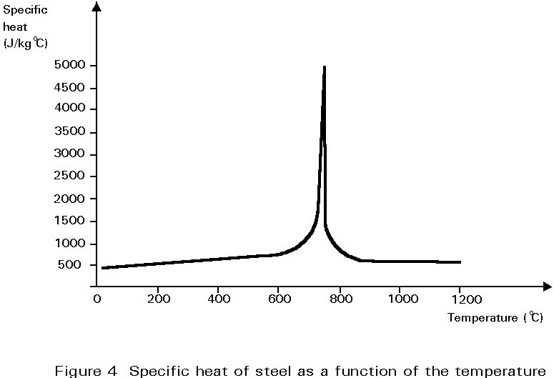
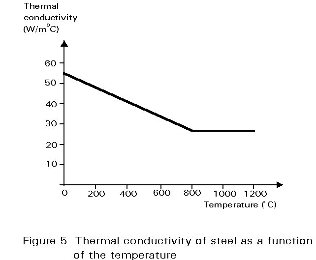
The quantity ks /rscs is known as the thermal diffusivity and varies with the temperature.
The specific mass of steel (rs) can be considered independently from the temperature (rs=7850kg/m3); while the thermal conductivity ks and the specific heat cs are dependent of the temperature (Figures 4 and 5) but for a simplified calculation it is possible to make reference to constant values (cs=520 J/kg°C and ks = 45 W/m°C, for all grades of steel).
The solution of the thermal transient can be obtained by numerical methods as in the general case; but thermal conductivity is high enough to allow differences of temperature in the cross-section to be neglected.
This assumption means that thermal resistance to heat flow is negligible. Any heat supplied to the steel section is considered to be instantly distributed to give a uniform steel temperature. With this assumption the energy balance can be made not only with reference to an infinitesimally small element, but also to the whole section of the exposed steel element (Figure 6).
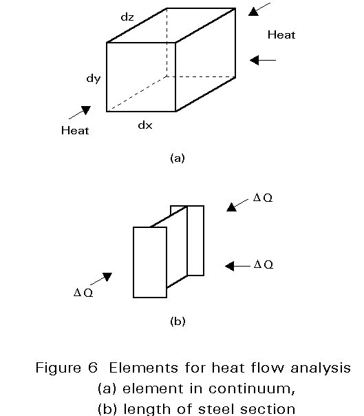
The quantity of heat transferred per unit length in the time interval Dt is:
D
Q = K . Am . (qf - qs) . Dt (2)where:
K is the total heat transfer coefficient (W/m2°C)
Am is the perimeter surface area per unit length exposed to fire (m2/m)
q
f is the temperature of hot gases (°C)q
s is the temperature of steel during the time interval Dt (°C)If this quantity of energy is entirely absorbed by the section, i.e. no loss of heat is considered, the internal energy of the unit length of a steel element increases by the same quantity:
D
Q = cs . rs . A . Dqs (3)where:
A is the cross-sectional area of the member (m2).
The temperature rise of the steel is given by combining Equations (2) and (3) as follows:
Dqs = [K/(cs/rs)].[Am /A].(qf - qs).Dt (4)
Solving this incremental equation step by step gives the temperature development of the steel element during the fire. To assure the numerical convergence of the solution some upper limit must be taken for the time increment Dt. In Eurocode 3 Part 1.2 [1] it is suggested that:
![]()
where:
D
t is in secondsAm /A is in m-1
It is apparent that an important parameter in determining the rise of temperature of the steel section is Am /A. This is often known as the "section factor" (sometimes given as F/V, or A/V, or Hp /A in different countries), see Figure 7.

When the profile is in contact with another element, for example, a concrete slab, which has a thermal conductivity greatly lower than the thermal conductivity of the steel, the effective exposed perimeter Am must be calculated taking into account only the part of the surface directly exposed. This requires an assumption of an adiabatic condition at the contact surface. The result is a safe solution: in fact some thermal energy passes through the colder body and, if it is neglected, the increase of the temperature in the steel element is higher.
It is very important to understand this point, because it gives the key to deciding if the simplified solution of the thermal problem is appropriate or if it is necessary to solve the complete heat transfer equation.
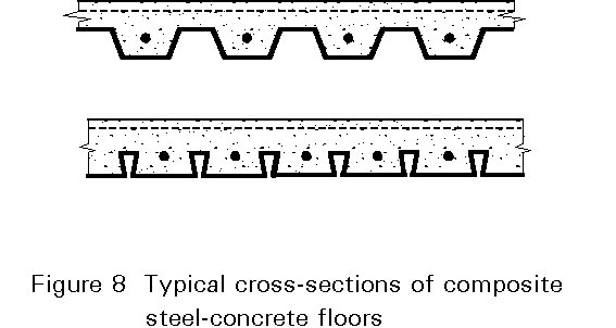
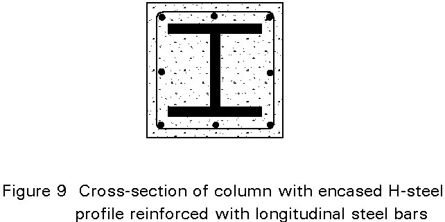
For instance it is appropriate to consider the thermal gradients in the steel cross-section or the heat flux transmitted from the steel to the concrete where the concrete slab is supported by a profiled steel sheet or in composite elements (Figures 8 and 9). In this case a finite element model can be used.
Eurocode 3 Part 1.2 permits many practical problems to be solved in a simplified way [1].
Heat transfer information is presented for bare elements, as well as for protected elements. Two types of coating are considered for protected elements: dry insulation materials, and materials containing a significant amount of moisture.
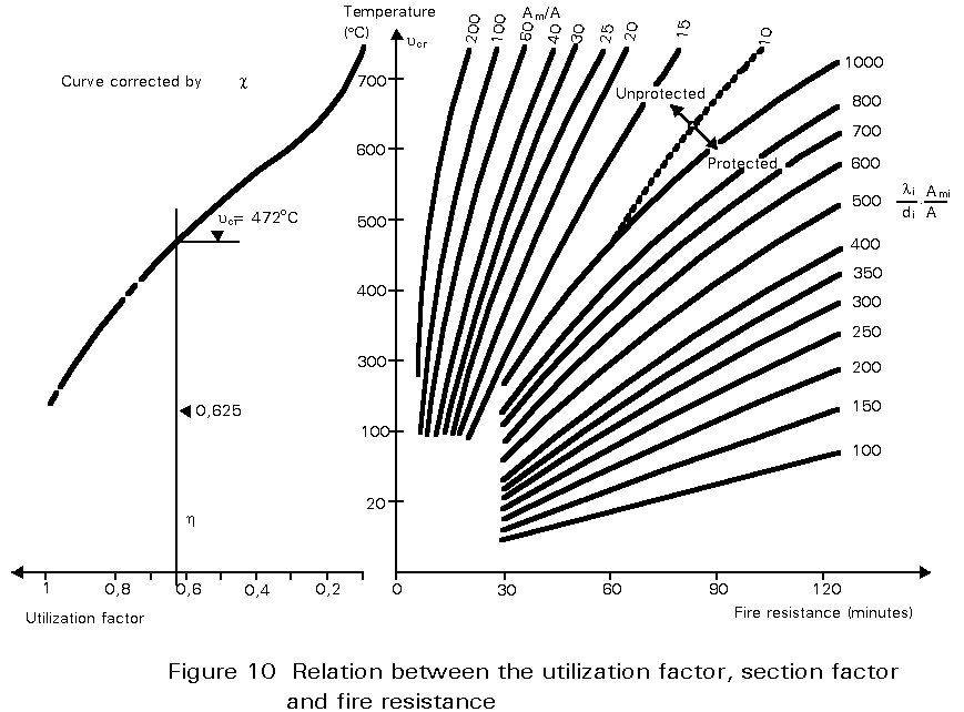
The ECCS publication 'European Recommendations for Fire Safety of Steel Structures' [2] also gives a simplified formula which expresses the relationship between the time, t, of exposure under a standard fire (expressed in minutes), the critical temperature qs,cr of the element, the section factor Am /A and the properties of the insulation materials, their thickness d and their thermal conductivity li.
For unprotected elements the equation is:
t = 0,54 (qcr - 50) (Am /A)-0,6
It can be solved in two ways:
q
cr = 1,85 t (Am /A)0,6 + 50or
Am /A = 0,36 [(qcr - 50)/t]1,67
and is valid within following ranges:
t = 10 to 80 min
q
cr = 400 to 600°CSimilarly, for sections protected by a light insulation material, the equations are:
t = 40(qcr - 140).[dA/liAm]0,77
or
d = 0,0083 [t/(qcr - 140)]1,3 .[Am/A].li
In the above equation d is the protection thickness (in metres) and li is the thermal conductivity of the material (in W/m°C).
These equations can be expressed also in a nomogram which is very practical for design purposes (Figure 10).
Equation (4) shows the three principal factors on which the increase of temperature of steel depends: the total heat transfer coefficient the ratio between the exposed perimeter of the element Am and its cross-section A; and the difference between the temperatures of the hot gases and the steel element.
The total heat transfer coefficient, K, depends on the heat transfer coefficients for convection and radiation, ac and ar, and, if there is a protective coating, on the thermal conductivity of the protective material and its thickness, such that:
K = {1/(ac + ar) + d/li}-1 (5)
For the usual condition of fire convection (as in a fire test furnace) the value of ac can be assumed:
a
c = 25 W/m2°C (6)while ar can be calculated by the expression:
ar = 5,77er {(qf + 273)4 - (qs + 273)4}×10-8/(qf - qs)
where er is the resultant emissivity of the flames, combustion gases and steel surface. Its value can be assumed according to Eurocode 3 [1], i.e.
e
r = 0,5The value of the section factor (Am /A) can vary over a very large range. The rate of temperature rise in a small thick section will be slow, whilst in a large thin section it will be more rapid.
The differences between section factors are the principal reason for the different behaviour of different steel elements exposed to fire. If the thermal inertia is larger, the increase of temperature is slower and the fire resistance is higher under the same loads as a result.
Values of section factors can be found in many publications. It must be noted that the section factor Am /A represents the ratio of the effective surface exposed to fire to the volume of the element. Where there is a protective coating, the surface to take into account is not the external surface of the profile, but the inner as, for instance, in the case of boarded encasement (Figure 7).
Two different composite elements are to be considered; composite columns and composite slabs.
For composite columns (Figure 11), a distinction is made between:
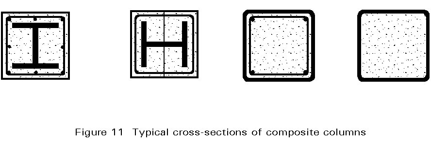
a. rolled I-profiles encased in concrete
b. rolled I-profiles with concrete between the flanges
c. concrete filled steel sections with or without reinforcement.
For composite slabs, the discussion is limited to composite concrete slabs with profiled steel sheet. Some typical cross-sections are shown in Figure 8.
The rules are based on the ECCS-Technical Notes for the calculation of the fire resistance of composite columns and composite concrete slabs with profiled steel sheet, exposed to the standard fire [3, 4]. These Technical Notes provided for designers reflect the present state of knowledge based on recent research results.
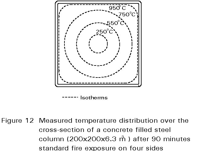
ISO standard fire exposure on all sides of the column is taken as the starting point. A uniform temperature distribution is assumed over the height of the column. Under practical fire conditions, however, a significant non-uniform temperature distribution in the concrete over the cross-section must be expected, as shown in Figure 12 for a concrete filled steel column.
As a consequence, two dimensional heat flow models must be used. The calculation of the temperature field over the cross-section is only possible by means of a computer. In practice this means that a separate thermal analysis must be made for all relevant cross-sections.
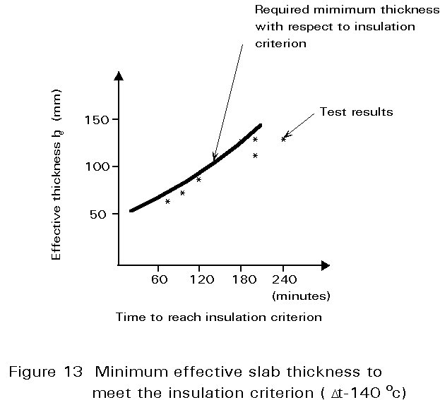
Composite slabs have not only a load bearing function but also a separating function in comparison to many traditional building components. As a result the insulation and integrity criteria should be considered when determining the fire resistance of composite slabs. For composite steel-concrete floors the integrity criterion is not difficult to fulfil. Normally the floor slab is cast in situ producing joints which are adequately sealed. Cracks which may occur in the concrete during fire exposure are unimportant because the steel sheet will prevent penetration by flames and hot gases. For these floors an explicit check on integrity is generally not necessary.
The following discussion considers the analysis for the criteria of insulation. Rules are presented for determining the temperature distribution as far as such information is necessary to evaluate the load bearing resistance. The rules concentrate on the required additional reinforcement, since without such reinforcement the fire resistance of composite slabs is only about 30 minutes.
As for composite columns, two-dimensional heat flow models are necessary for concrete slabs with profiled steel sheets. These models are however too cumbersome for every day design. To overcome this problem, the profiled slab is schematized to a flat slab with an effective thickness equal to a weighted average of the real slab thickness. For various periods of standard fire exposure, temperature distributions can then be determined. From such distributions a rule for minimum slab thickness necessary to fulfil the criterion of insulation can be derived. This rule is given in Figure 13 together with some test results. It is seen that conservative solutions are obtained.
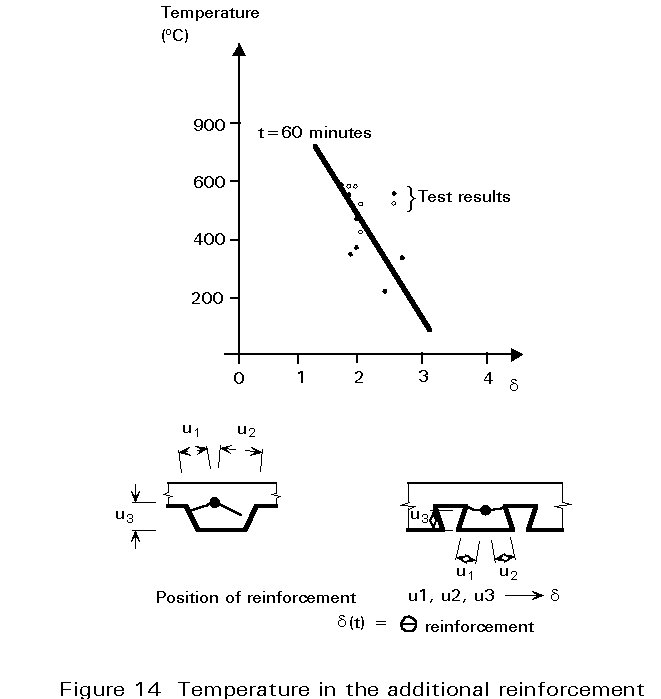
The temperature of the additional reinforcement plays a crucial role in structural analysis. Therefore, experimentally determined equations have been established from which this temperature may be calculated as a function of the position of the reinforcement bar in the slab, (given by u1, u2, u3) and the period of standard fire exposure, t. Figure 14 shows the results of some validation tests.
[1] Eurocode 3 Part 1.2, 'Structural Fire Design of Steel Structures' CEN (in preparation).
[2] European Convention for Constructional Stelwork, "European Recommendations for Fire Safety of Steel Structures", ECCS Publication 30, Elsevier, 1983.
[3] European Convention for Constructional Steelwork, "Calculation of the Fire Resistance of Composite Columns Exposed to the Standard Fire", 1986.
[4] European Convention for Constructional Steelwork, "Calculation of the Fire Resistance of Composite Concrete Slabs with Profiled Steel Sheet Exposed to the Standard Fire", 1984.