
ESDEP WG 4B
PROTECTION: FIRE
Demonstration of calculation of load bearing resistance of structural elements submitted to an increase of temperature. Guideline for the calculation of the fire rating of steel and composite elements.
Lecture 4B.1: Introduction to Fire Safety
Lecture 6.3: Elastic Instability Modes
Lectures 2.3: Engineering Properties of Steels
Lecture 4B.2: Background to Thermal Analysis
Lecture 14.3: Analysis of Portal Frames: Plastic Analysis
The failure resistance of a structural element subjected to fire is calculated from the applied load during the fire and plastic theory. Differentiation is made between bending elements and axially loaded elements and between uniformly heated sections and sections with thermal gradients. The main factors influencing stability in fire are presented. Structural analysis of composite columns and composite slabs is also discussed.
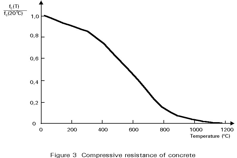
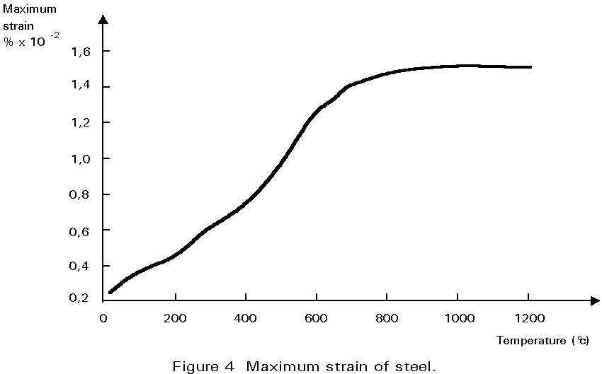
The increase of the temperature of steel and concrete in composite steel-concrete elements, leads to a decrease of mechanical properties such as yield stress, Young's modulus, and ultimate compressive strength of concrete (Figures 1 - 4) Thus, when a steel or a composite structure is submitted to a fire action, its load bearing resistance decreases. If the duration and the intensity of the fire are large enough, the load bearing resistance can fall to the level of the applied load resulting in the collapse of the structure (Figure 5). This state is illustrated by:


Pu (qcr) = P
where:
P is the applied load in fire conditions
Pu (qcr) is the load bearing resistance for a temperature qcrit (the critical temperature), and
Pu is the load bearing resistance at room temperature.
The objective of this lecture is to give the background for structural analysis of this situation.
The applied load is obtained by considering the accidental combination of the mechanical actions such as: dead load, live load, wind (only for bracing), snow.
Due to the low probability that both fire and extreme severity of external actions occur at the same time, only the following accidental combinations are considered:
1,0 GK + y1 QK,1 + S y2,i QK,i
where:
GK is the characteristic value of permanent actions
QK,1 is the characteristic value of the main variable actions
QK,i is the characteristic value of other variable actions
y
1 is the frequent value of the main variable actionsy
2,i is the average of the other variable actions.Generally, in fire: y1 = 0,5 and y2,i = 0
Apart from bracings, QK,1 and QK,2 generally correspond to imposed loads and snow loads.
The calculation of the load bearing resistance of a structure submitted to fire can be made in several ways depending on the kind of structure and the requirement for the duration of stability in fire.
The simplest method of calculation is an analysis in which the structure is represented by individual members considered directly exposed to fire. In such calculations, support and boundary conditions should be assumed as for normal conditions of use. External forces and moments on the structural member are deduced from a global structural analysis for normal conditions of use.
This analysis is generally sufficient when requirements of fire stability are expressed in terms of duration of a standard fire.
The load bearing resistance can also be deduced from a sub-assembly analysis or a general structural analysis by taking into account interaction between the various members, expansion, and localisation of the fire.
Such sub-assembly analysis leads to a more accurate knowledge of the behaviour of the structure in fire. However these analyses require the use of computer modelling.
The critical temperature (qcrit) which leads to the failure is calculated for a steel structure assuming a uniform temperature distribution along and across the members.
Some examples of calculation of the critical temperature where the theory of plasticity applies are given below.
Four kinds of structural elements are considered: tensile members, columns, beams and beam columns [1].
At room temperature, the ultimate tensile resistance is given by:
Np = A . fy
where:
A is the cross-section of the member,
fy is the yield stress.
At a given uniform temperature q, through the member, the ultimate tensile resistance is:
Np (q) = A . y(q) . fy
y
(q) is the strength reduction of steel at q, and is given by Figure 2.The collapse of the member will occur at the temperature qcrit when:
Np (qcrit) = N
where: N = the applied load in fire conditions
This formula can also be written as:
A . y(qcrit) . fy = A . s
where: s = applied stress in fire conditions
Thus y(qcrit) = s/fy
or, y(qcrit) = A s/A.fy = N/NP = P/Pu
Therefore, knowing P/Pu it is possible to determine, using Figure 2, the value of the steel critical temperature (qcrit) for which y(qcrit) is equal to P/Pu.
A similar calculation as for tensile members applies but the analysis has to include the effects of column buckling. This is taken into account by modifying the ultimate load bearing resistance by the buckling coefficient. In order to correlate test results on columns with the basic performance of steel at elevated temperatures, it is necessary to consider a correction factor, k, such that:
y
(qcrit) = kP/PuBoth P and Pu should be evaluated using the appropriate bucking coefficient. The buckling coefficient for a column at a temperature q is given by:
c(q) = 1/{f(q )
+ [f(q )2 -![]() (q)2]1/2
£ 1
(q)2]1/2
£ 1
where: f(q) = 0,5 (1 + a(![]() (q) - 0,2) +
(q) - 0,2) +![]() (q)2)
(q)2)
and ![]() (q) =
(q) = ![]()
The end conditions of the column have to be taken into account. Generally the cold parts at the ends of the column lead to a lower value of buckling slenderness, l, than under normal conditions.
The value of the correction factor, k, is equal to 1,2. It is used to compensate for the choice of fy which is related to the effective yield stress (the stress level at which the stress-strain relationship of steel tends to a yield plateau for a certain temperature) and not to the yield stress at 0,2% strain.
The maximum bending moment of a simply supported beam uniformly loaded (by load P over its length) is:
M = PL/8
and the corresponding maximum stress is:
s
= M / Sewhere:
Se is the minimum elastic modulus of the section
To obtain collapse according to plastic theory, it is necessary that a plastic hinge forms at mid-span. The failure will occur when the total load on the beam is:
Pu = 8 Mu/L
where:
Mu is the plastic bending moment resistance given by:
Mu = Z . fy
and Z is the plastic modulus of the section
When the temperature is equal to q, this plastic bending moment resistance is equal to:
Mu(q) = Z . y(q) . fy
For a beam subject to a load of P, the collapse will occur at qcrit when:
Pu(qcrit) = P or Mu(qcrit) = M
i.e. when y(qcrit) = Se . s/Z . fy = s/(f . fy) = P/Pu
where f = Z/Se is the shape factor of the steel section (~ 1,10 to 1,3).
When the beam is statically indeterminate, several plastic hinges are necessary to obtain collapse. For beams designed accordingly to elastic theory, a special coefficient (c) has to be taken into account in the calculation of the critical temperature for the collapse condition. This coefficient takes account of the redistribution of moments in the intermediate structure (plastic analysis).
For example a continuous beam on three supports, uniformly loaded, has a maximum bending moment (M) at the middle support, where:
M = PL/8
i.e. a value equal to that at midspan of a simply supported beam.
In fire a plastic hinge will form at this middle support as the temperature increases when:
Mu(q1) = M
For the simply supported beam the failure occurs at this temperature (q1), whereas the continuous beam still needs an increase of temperature up to qcrit in order that other plastic hinges form in the spans (Figure 6), leading to collapse of the beam.
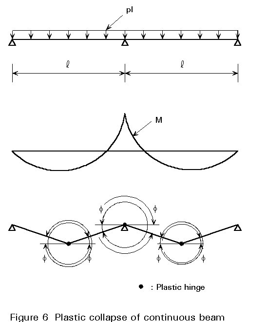
The load bearing resistance of this continuous beam is:
Pu(qcrit) = 12 . Mu(qcrit)/L
so y(qcrit) = 8.Se.s/12 . Z . fy = 8.s/12.f.fy = P/Pu
The ratio 12/8 = 1,5 = c is the statically indeterminate coefficient, or plastic redistribution coefficient.
When axial force and bending moment act together on the same structural element, its critical temperature can be obtained from the following formula:
![]()
where:
c
min is the lesser of the buckling coefficients cy and cz about the yy or zz axis andky and kz are the reduction factors for the yy and zz axes respectively (see Lectures 7.10)
The various parameters which have a strong influence on the critical temperature may be found by study of the above mentioned formulae.
The general formula for bending elements is:
y
(qcrit) = s/c.f.fyc is the coefficient given in Section 4.3.2 above.
and for columns and beam columns is:
y(qcrit) = N/cminNp + S(kiMi/Mpi)
These show that y will decrease and subsequently the critical temperature will increase, when:
The critical temperature can also be increased by using other steel grades with better behaviour when heated.
In reality it is very seldom that temperature across and/or along elements is uniform.
Thermal gradients occur for several reasons, for example, the presence of a slab or a wall near the flange of a steel profile, localised fire, connection between column and beam (leading to a concentration of steel), element located outside a fire compartment. Thermal gradients have different effects on the mechanical behaviour of structural elements.
For beams, a lower temperature in the upper flange will lead to an increase of the ultimate bending moment (Figure 7). For continuous beams, a lower temperature in the area of the middle support will lead, either, to more time to reach the temperature at which the plastic hinge occurs, or, to a displacement of this hinge to a cross-section where an optimum ratio between bending moment and temperature is obtained.

Thus the reduction of the temperature in a part of a beam leads to an increase of its load bearing resistance.
Such thermal gradients can be taken into account, either by calculating the load bearing resistance as explained in Section 5 or by using the global coefficient, called the Kappa-factor. The Kappa-factor is a global coefficient to account for the beneficial influence of thermal gradient for beams. For this purpose the general formula for a beam then becomes [2].
y
(qcrit) = k.s/c.f.fywhere:
For columns, a lower temperature at the ends will effectively decrease the buckling length. However a thermal gradient in a cross-section, especially when this section is near the mid-height, will cause curvature of the column. An additional bending moment will be created, increasing the stress in the column. However, in general, non-uniform heating increases the strength of the columns because the colder parts are still able to resist compression.
Composite sections in which concrete and steel are used, are subject to thermal gradients when heated on one or several of their sides. The load bearing resistance of beams and slabs can be determined on the basis of simple plastic theory. To calculate the load bearing resistance of a member with a thermal gradient, the simplest approach is to divide the section into elements each with its appropriate temperature and mechanical properties.
A composite beam (steel section and flat concrete slab) generally has a distribution of temperature after a given time of fire exposure as shown in Figure 8.
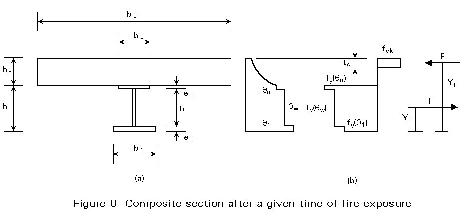
In a positive moment zone, the ultimate bending moment resistance, assuming the neutral axis is in the thickness of the concrete slab, is calculated by considering an equilibrium between tensile force (in the steel section) and compressive force (in the upper part of the concrete slab).
The tensile force summed over the three parts of the steel section is:
T = S3i=1 Ai y(qi)fy
where:
Ai is the area of lower flange, web and upper flange of the steel profile
q
i is the respective temperatureThe point of application of this force is the plastic neutral axis at elevated temperature of the 3 parts of the steel action.
In order to balance this tensile force, a layer of the concrete slab is compressed (Figure 8b) such that:
T = C = b t fck
where:
b is the effective width of the slab
t is the thickness of the compressive zone
fck is the ultimate strength of concrete
This equation is only valid when the temperature of the compressive zone is approximately uniform. If a strong thermal gradient exists over the height of this zone, it is necessary to divide it into different layers having approximately uniform temperature and to sum the contribution of these layers.
However normally this composite floor generally has also to achieve insulation criteria, i.e. the temperature on its external face has to be less than 140°C. At this temperature, it can be assumed that the concrete strength remains as it is at room temperature.
The ultimate bending resistance of the composite section is:
M+u(q) = T . z
where z is the distance between the points of application of the tensile and the compressive forces.
For continuous beams, the determination of the full load bearing resistance also requires the calculation of the negative plastic bending moment (M-u(q)).
For this negative plastic moment, the tensile force is taken by the reinforcement bars located in the upper part of the concrete slab and the compressive force is taken by the steel profile and, if necessary, by a lower part of the concrete slab.
For this situation, it is assumed that stability in fire is maintained if the isostatic bending moment (M) of the applied load in a span is lower or equal to the sum of the positive and negative moment resistances of the composite section, as follows:
M+u(q) + M-u(q) ³ M
The calculation of the fire behaviour of composite concrete slabs with profiled steel sheet is made using the same theories as for composite beams.
The only major modification is that after 30 minutes of ISO fire, the steel sheet is not taken into account when calculating the mechanical behaviour of the element.
For this situation, only the re-bars can be used to compensate the tensile force because the tensile strength of concrete does not contribute to the load bearing resistance at elevated temperature and is ignored. Only 30 minutes fire resistance can generally be achieved for non-reinforced slabs.
Simple plastic theory cannot be used for columns (in contrast to beams and slabs) and an incremental elasto-plastic approach is necessary.
For composite columns another complication arises as a direct consequence of the non-uniform temperature distribution over the cross-section. The distribution causes additional stresses in the cross-section due to restrained thermal elongation (Figure 9).
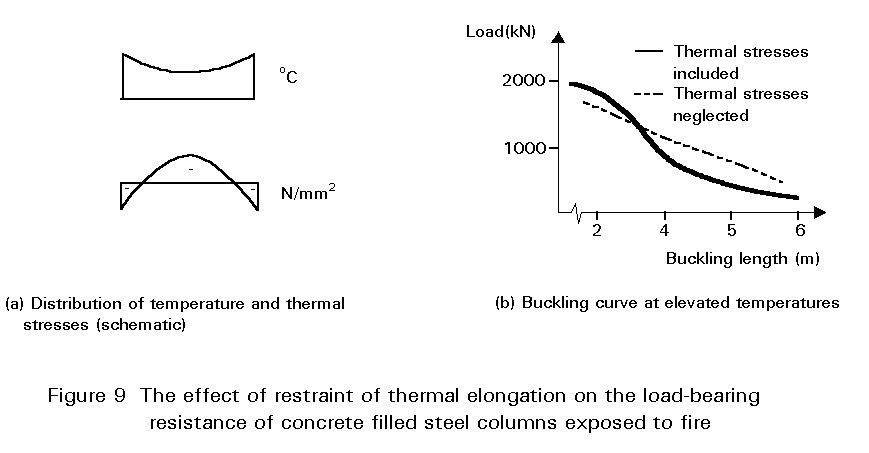
These thermal stresses may have a significant influence on the load bearing resistance of composite columns, as is illustrated by the buckling curves (Figure 9). Both curves are for a reinforced, concrete filled steel column after 90 minutes standard fire exposure. The continuous curve is based on a calculation model which takes the thermal stresses into account; the dashed curve neglects the effect of the thermal stresses.
Structural analysis of composite columns should therefore, ideally, be based on refined models, i.e. models allowing for a precise thermal and mechanical analysis.
The numerical complexity of such physical models however, quickly increases with the growing precision of the analysis. The complexity has drawbacks, for example where design information requires a great number of systematic calculations. For this reason limited, more approximate, models have been developed. These simpler methods occasionally require the introduction of semi-empirical correction factors. They should therefore be used with caution when extrapolating outside the range of experimental evidence.
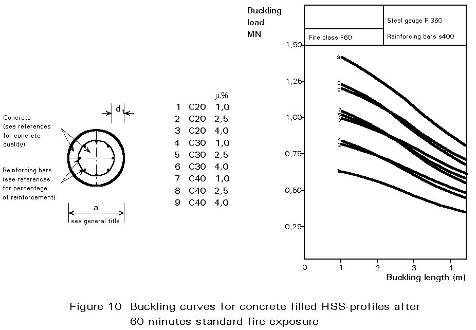
The ECCS-Technical Note on the calculation of the fire resistance of composite columns provides design information in the form of buckling curves for various cross-section dimensions, profiles and reinforcement and for periods of standard fire exposure of 30, 60 ,90 and 120 minutes [3]. An example of a design chart is given in Figure 10.
There is no special problem in determining the fire resistance of connections between columns and beams. Due to the concentration of steel in this area, the temperature of the connection is lower than that of the adjacent members. It may be possible to consider some positive effects of partial continuity of beams when there is a connection which is only designed to support shear forces at room temperature.
[1] Barthelemmy, B. and Kruppa, J., "Résistance au feu des structures acier - béton -bois", Eyrolles, 1988.
[2] European Convention for Constructional Steelwork, "European Recommendation for Fire Safety of Steel Structures", Elsevier, Publication 30, 1983.
[3] European Convention for Constructional Steelwork, "Calculation of the Fire Resistance of Centrally Loaded Composite Steel-Concrete Columns Exposed to the Standard Fire", Publication 55, 1988.