ESDEP WG 14
STRUCTURAL SYSTEMS: BUILDINGS
To present and illustrate procedures for the design of multi-storey buildings relating to the behaviour of beams, columns and connections. Special attention is paid to the influence of the design of partial-strength connections on the frame behaviour.
Lecture 14.8: Classification of Multi-Storey Frames
Lecture 11.6: Moment Connections for Continuous Framing
Lecture 11.7: Partial Strength Connections for Semi-Continuous Framing
Lecture 14.10: Simple Braced Non-Sway Multi-Storey Buildings
The influence of partial strength and semi-rigid connections on the design of building frames of structural steel is considered. Plastically designed connections in elastically designed frames and elastically designed connections in plastically designed frames are discussed.
The main structural elements of steel framed multi-storey structures are the columns, the beams and their connections. Conventionally the beam-to-column connections are considered to be either pinned or rigid.
In the case of pinned or 'simple' connections, the frames have to be stabilised by appropriate bracing systems. Such frames are named braced frames by Eurocode 3. Their design is treated in detail in lecture 14.10.
The term 'rigid' in this context implies that the connection is capable of resisting moments with a high stiffness, i.e., the connection flexibility has a negligible influence on the distribution of movements in the frame connections. When the connections are rigid, the overall stability may be provided by the frame itself without the inclusion of specific bracing systems. These rigid-jointed or moment resisting frames are treated in lecture 14.14.
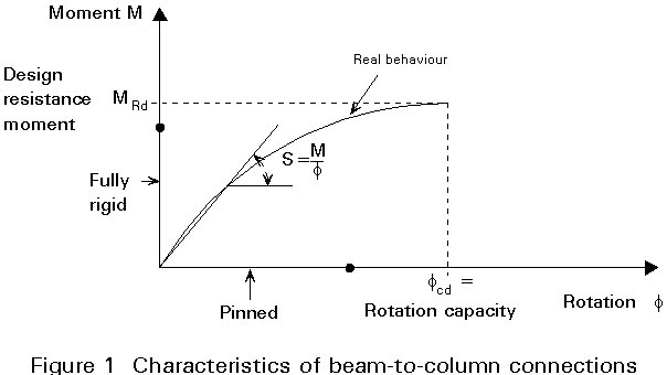
Although the idealisation of connection stiffness as pinned or rigid has been applied exclusively in the past it is generally recognised that the real behaviour of the connections is never as ideal as assumed in the analysis (Figure1). The two cases, pinned and fully rigid, actually represent extremes of connection behaviour. In reality, the connections behave somewhere between those limits, that is they behave as semi-rigid [1, 2].
A further classification of moment resisting connections relates to their strength. A 'full-strength' connection is a connection that can at least develop the bending strength of the elements it connects. A 'partial-strength' connection has a lower design strength than that of the elements it connects.
The rotation capacity of a moment-resisting connection can also be important. For example a beam with partial-strength end connections can be designed plastically if the connection rotation capacity is sufficient to ensure the development of an effective hinge at midspan.
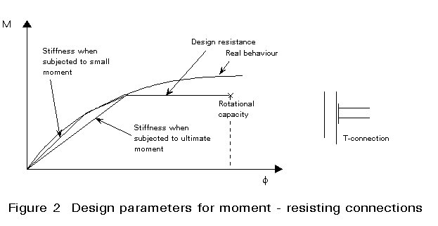
Figure 2 shows the moment/rotation diagram of a beam to column connection. For design purposes the real connection behaviour can be represented by a bi-linear or tri-linear diagram in which the following properties can be distinguished.
·
The design resistance of the connection·
The stiffness of the connection when subjected to small moments·
The stiffness of the connection when subject to ultimate moments·
The rotation capacityThe influence of connections on frame behaviour is treated separately for partial-strength and semi-rigid connections.
Braced frames are in general designed based on strength conditions and unbraced frames are generally designed based on stability and deformation conditions. Therefore partial strength connections are mainly applicable for braced frames and semi-rigid connects for unbraced frames.
The end rotation of a simply supported beam under a uniform vertical load and external negative moments M (Figure 3) is given by
f = ![]() (1)
(1)
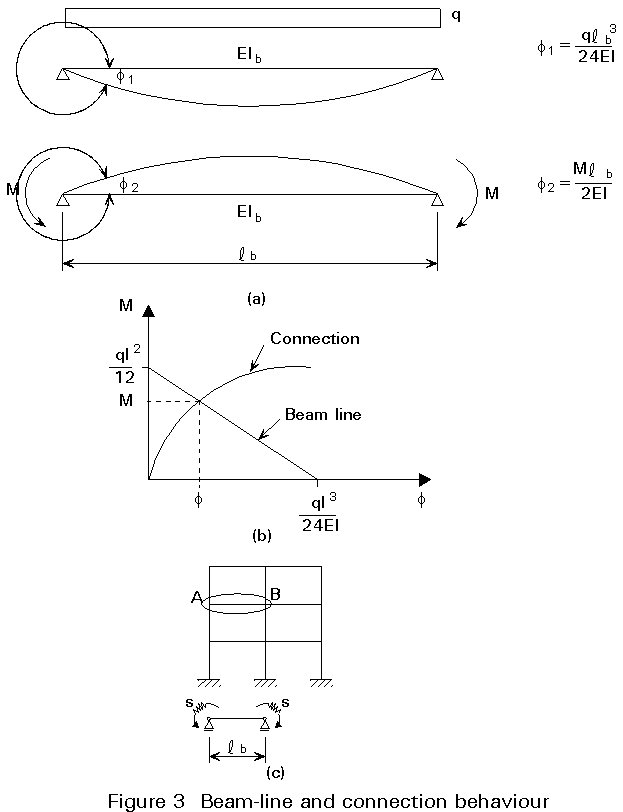
The (M-f) response represented by equation 1 is a straight line which is called the beam line as show in Figure 2b). In real frames the end moment restraint is provided by the rigidity of the connection S = M/f as shown in Figure 2c and therefore the actual end moment and the end rotation of the beam is given by the intersection of the beam line with the connection characteristic as shown in Figure 2b.
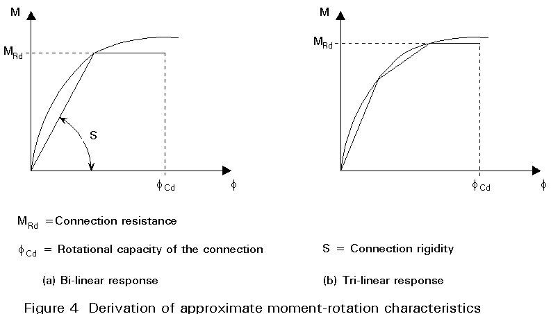
For practical design situations the actual non-linear connection behaviour has to be approximated. Various approximate connection characteristics are in Figure 4. The connection behaviour is characterised by its moment resistance MRd, its rotational capacity fcd and its rigidity s = M/f.
In order to determine if the connection flexibility S-1 needs to be included in the overall frame analysis it is important to examine its influence on the behaviour of the frame [3]. This is studied subsequently for single storey braced and unbraced frames as shown in Figure 5a.
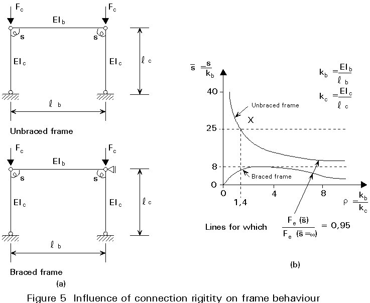
Figure 5b presents the relationship between the relative connection-to-beam rigidity
![]() and the relative beam-to column rigidity r in order that the flexibility of the connection reduces the Euler buckling load of the rigid frame by 5%.
and the relative beam-to column rigidity r in order that the flexibility of the connection reduces the Euler buckling load of the rigid frame by 5%.
An example of the evaluation of the curve for an unbraced frame is given by considering point x, where r = 1.4 and
![]() = 25.
= 25.
Assume kb = 10
If r = 1.4; kc = 10/1,4= 7.14
If ![]() = 25; s = kb = 250
= 25; s = kb = 250
First examine case with fully rigid connection ![]() = ¥
= ¥
k1 = kb = 10
From EC3 Annex E
h
1 = 1.0; h2 = = 2.391
Examine case with semi-rigid connection
For symmetrical double curvature in beam, end rotational stiffness = ![]() , therefore effective stiffness of connection in calculation of k1 is
, therefore effective stiffness of connection in calculation of k1 is ![]() based on ratios of
based on ratios of ![]() to
to ![]() .
.
Hence,
k1 = ![]() . kb =
. kb = 
From EC3 Annex E
h
1 = 1.0 h2 =
Hence reduction of elastic critical load in the presence of such connection flexibility is given by:
![]() =
=  =
= ![]()
i.e. for a frame with r = 1.4, a 5% reduction in elastic critical load factor is caused by
![]() of 25.
of 25.
In real frames the most important quantity is the ultimate limit load Fu of the frame rather than the Euler buckling load Fe. This can be found by the Merchant-Rankine formula (lecture 7.7) for the unbraced frame. If Fpl is the plastic failure load of the frame then according to the above formula the ultimate load is given by:
![]() (2)
(2)
From equation 2 it is obvious that a 5% drop of the Euler buckling load Fe due to connection flexibility leads to a drop in load carrying capacity of the frame Fu by not more than 5%.
The previous discussion leads to the observation that for a given frame configuration, depending on the parameter r , the minimum required connection stiffeness
![]() may be determined from Figure 5b that does not lead to a decrease of the frame ultimate capacity by more than 5%. If the actual stiffeness of the connection is smaller than that one determined from Figure 5b, the connection flexibility shall be taken into account in the frame analysis.
may be determined from Figure 5b that does not lead to a decrease of the frame ultimate capacity by more than 5%. If the actual stiffeness of the connection is smaller than that one determined from Figure 5b, the connection flexibility shall be taken into account in the frame analysis.
In Eurocode 3, a further simplification is made, see Figure 6. Constant boundary factors
![]() are chosen for the braced and unbraced frames rather than values dependent on r.
are chosen for the braced and unbraced frames rather than values dependent on r.
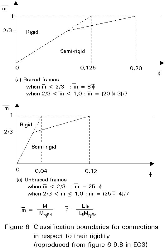
For braced frames the boundary value of ![]() is equal to 8 as shown in Figure 6b. That means that if s ³ 8kb a connection may be treated as rigid, otherwise as semi-rigid. This is illustrated in Figure 6a.
is equal to 8 as shown in Figure 6b. That means that if s ³ 8kb a connection may be treated as rigid, otherwise as semi-rigid. This is illustrated in Figure 6a.
For unbraced frames the relevant value of ![]() is 25, which means that if s ³ 25kb a connection may be treated as rigid, otherwise as semi-rigid. Figure 6b illustrates this case.
is 25, which means that if s ³ 25kb a connection may be treated as rigid, otherwise as semi-rigid. Figure 6b illustrates this case.
According to Figure 5b the boundary value ![]() = 25 for unbraced frames covers only the cases when r ³ 1,4. For r < 1,4 this value is unsafe. This situation is investigated below.
= 25 for unbraced frames covers only the cases when r ³ 1,4. For r < 1,4 this value is unsafe. This situation is investigated below.
Frames for which r < 0.1 are not realistic, so the value r = 0.1 can be used as a boundary.
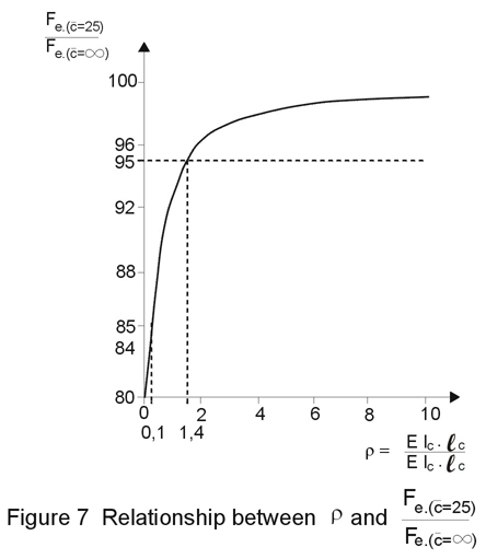
Figure 7 shows the relationship between r and (FE(![]() )/FE(
)/FE(![]() = ¥). 100%. When r =0.1, the Euler buckling load based on
= ¥). 100%. When r =0.1, the Euler buckling load based on
![]() = 25 is 85% of the Euler buckling load for
= 25 is 85% of the Euler buckling load for
![]() = ¥ .
= ¥ .
The carrying resistance of the frame based on the Merchant-Rankine formula has reduced as follows:
1/Fu(![]() =
¥) = 1/Fpl + 1/FE(
=
¥) = 1/Fpl + 1/FE(![]() =
¥)
=
¥)
where Fu( ![]() =
¥) is the carrying resistance of the frame with rigid connections
=
¥) is the carrying resistance of the frame with rigid connections
1/Fu(![]() =
¥) = 1/Fpl + 1/XFpl
=
¥) = 1/Fpl + 1/XFpl
where:
X = FE(![]() = ¥) / Fpl
= ¥) / Fpl
1/Fu(![]() = ¥) = (1+ 1/X) / Fpl
= ¥) = (1+ 1/X) / Fpl
Fu(![]() = ¥)
= {X/(X + 1)}/Fpl
= ¥)
= {X/(X + 1)}/Fpl
The following relationship holds for connections where ![]() = 25
= 25
1/Fu(![]() =
25) = (1+ 1/0,85X)Fpl
=
25) = (1+ 1/0,85X)Fpl
Fu(![]() =
25)
= {0,85X/(1 + 0,85X)}Fpl
=
25)
= {0,85X/(1 + 0,85X)}Fpl
The reduction of the carrying resistance is:
D = {Fu(![]() = ¥ )
- Fu(
= ¥ )
- Fu(![]() = 25)}/Fu(
= 25)}/Fu(![]() = ¥ )
. 100%
= ¥ )
. 100%
Even for a very slender frame, namely FE(![]() = ¥) = Fpl, so X = 1, the reduction D = 8% and for X = 2 the reduction D = 5.6%.
= ¥) = Fpl, so X = 1, the reduction D = 8% and for X = 2 the reduction D = 5.6%.
It can be concluded that ![]() = 25 is a sufficiently safe boundary value for practical frames for the rotation stiffness of beam-to-column connection in unbraced frames in order to consider them as rigid.
= 25 is a sufficiently safe boundary value for practical frames for the rotation stiffness of beam-to-column connection in unbraced frames in order to consider them as rigid.
In Figure 6 the boundaries for the distinction between rigid and semi-rigid behaviour of the connection follows a tri-linear rather than a bi-linear characteristic. The reasons are:
a) experimental evidence shows that a beam-to column end-plate connection behaves elastically for up to at least 2/3 of its moment resistance
b) The beam characteristic is also not linear up to the plastic moment. Plastification in the beam theoretically starts at about Wel/Wpl = 0,9 for I sections.
Due to residual stresses a more practical figure is 70% of the beam plastic moment. It is therefore considered reasonable to alleviate the bi-linear characteristic of the connection by a third branch.
As far as the moment resistance of beam-to-column connections is concerned, classification is simpler. If the moment resistance of the beam-to-column connection is equal to the plastic resistance of the connected beam, the connection is considered as full-strength. If not, the connection is considered as partial-strength. On the basis of the boundary for the rotation stiffness and the boundary for the moment resistance a bi-linear moment-rotation characteristic is achieved.
If the moment-rotation characteristic of a beam-to-column connection lies on the left hand side and above the boundary lines, this connection can be classified as rigid and full-strength.
Connections may be designed either by elastic or by plastic theory. Since they are modelled mostly by rotational springs as shown in Figure 4a, it is important to determine the spring characteristic representing the behaviour of the connection. From the lay-out of the connections, its moment-rotation characteristic may be determined on the basis of Annex JJ of Eurocode 3. However, the initial estimate of the characteristic has to be modified with the type of global analysis (elastic or plastic) and the method of connection verification (elastic or plastic) as shown in Figure 8 reproduced from Annex JJ.
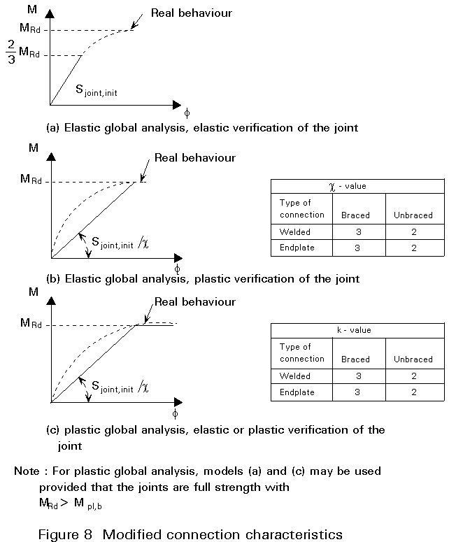
If the global analysis is elastic the spring behaviour is considered to be linear since the same applies also to the behaviour of the other structural elements (beams and columns). For this type of analysis the joint may be verified either on the basis of elastic or on the basis of plastic theory. In the former case, only the linear part of the connections characteristic is taken into account ie., the design moment of the connection is only 2/3 of its ultimate moment and its stiffness is equal to the initial value (Figure 8a). In the latter case the design moment of the connection is equal to its plastic moment but its stiffness is reduced by the factor c as shown in Figure 8b to take into account the non-linearities.
In the case of plastic global analysis, with partial strength joints, the spring behaviour of the connection is considered as bi-linear, since the same applies also to the behaviour of the beams and the columns of the frame. In that case the non-linear part of the connections is taken into account as shown in Figure 8c.
Obviously such connections should possess sufficient rotation capacity in order to be able to undergo the resulting plastic relations.
A last case is when plastic global analysis is applied with full strength joints. In this case no plastic hinge is formed in the joint and the joint model is linear according to Figure 8a or 8b. In order to be sure that no plastic hinge will form in the joint and bearing in mind the possible overstrength of the beam, the following conditions shall apply:
For Figure 7(a): 2/3 MRd ³ 1,2 Mpl,b
For Figure 7(b): MRd ³ 1,2 Mpl,b
The greatest problem in the practical design of frames with semi-rigid connection lies in the determination of the connection flexibility since this is only possible once the connection is designed. This means that there must be an iterative process between frame analysis and joint dimensions until a connection is found with the characteristics assumed in the analysis ie., one that is able to transmit the forces and moment and undergo the required rotation determined by the analysis.
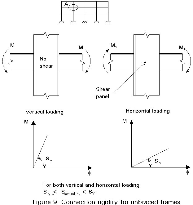
Specifically in the case of unbraced frames an additional parameter shall be taken into account in the modelling of connections. As illustrated in Figure 9, the deformation characteristic of the joint is different for the various loading conditions (vertical loading, horizontal loading) due to the large flexibility of the column web when submitted to shear. Since this case appears only for horizontal loading the joint behaviour is much softer in that case than in the case of vertical loading. In the normal case of both vertical and horizontal loading, the actual spring stiffness lies between the two values. This makes the practical design of unbraced frames with semi-rigid connections almost impossible.
[1] Chen, W F: Joint flexibility on steel frames, Elsevier Applied Science Publications Ltd, 1987
[2] Bjorhorde, R., Brozzetti, J., Colson, A.: Connections in Steel Structures, Elsevier Applied Science Publishers Ltd, 1988
[3] Background Document 6.09 to Eurocode 3, Beam to Column Connections, Commission of the European Communities, 1989