ESDEP WG 7
ELEMENTS
To describe the methods of beam-column analysis, either by verification of a single member or by verification of the whole frame.
Lecture 7.1: Methods of Analysis of Steel Structures
Lectures 7.10: Beam Columns
Lecture 6.2: General Criteria for Elastic Stability
Lecture 7.3: Local Buckling
Worked Example 7.10: Beam Columns
This lecture explains the basic methods of beam - column verification; this is done firstly for an isolated member, taking the end deformations and end forces from a global analysis of the whole frame and calculating the resistance using the rules given in Eurocode
3 [1]. The case where the member cannot be isolated from the frame structure is also covered by giving an alternative procedure, which yields an overall slenderness,
![]() , of the frame (including lateral-torsional buckling effects) that allows for frame verification using the European buckling curves.
, of the frame (including lateral-torsional buckling effects) that allows for frame verification using the European buckling curves.
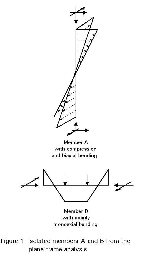
Normally, the design of an individual member in a frame is done by separating it from the frame and dealing with it as an isolated substructure. The end conditions of the member should then comply with its deformation conditions, in the spatial frame, in a conservative way, e.g. by assuming a nominally pinned end condition, and the internal action effects, at the ends of the members, should be considered by applying equivalent external end moments and end forces, Figure 1. Methods of verification for these members are given in Section 2.
A more general procedure is given in Section 3, for the case where members cannot be isolated from the frame structure in the way described above.
For the design of beam-columns, with mono-axial bending only, two checks must be carried out:
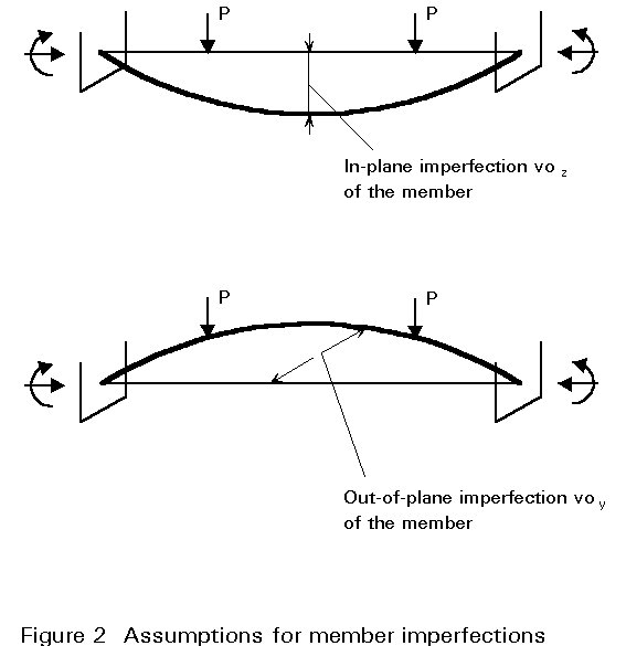
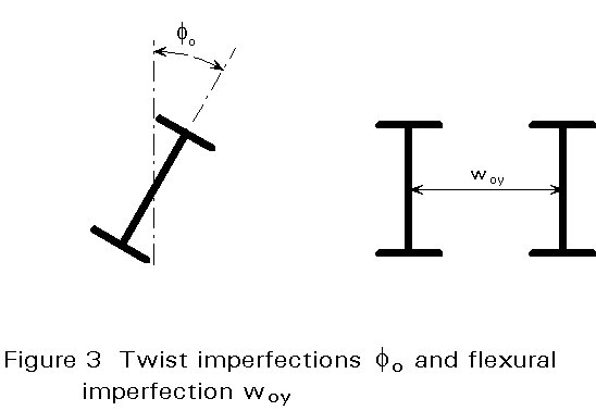
It has been found by test calculations that twist imperfections, r, of beam-columns that are susceptible to lateral-torsional buckling, can be substituted by flexural imperfections, see Figure 3.
Members with sufficient torsional stiffness, e.g. hollow section members, need not be verified for lateral-torsional bucking.
The in-plane or out-of-plane flexural buckling check is done using the interaction formula:
![]()
where cmin is the lesser of cy and cz and the factor ky is given by:
ky = 1 - (myNSd)/(cy Afy) £ 1,5
where:
m
y =b
My takes account of the shape of the moment distribution diagram between the member ends. Values for this are given in Table 1.In the case where lateral-torsional buckling is possible, the verification must be carried out using the following formula:
![]()
where cz refers to the direction of the lateral-torsional buckling.
c
LT is the relevant reduction factor for lateral-torsional bucklingkLT = ![]()
where:
m
LT = 0,15and bM is given by Table 1.
When the non-dimensional slenderness ![]() LT £ 0,4, the reduction coefficient cLT need not be taken into account. This rule may be used for spacing the lateral restraints to resist lateral-torsional buckling.
LT £ 0,4, the reduction coefficient cLT need not be taken into account. This rule may be used for spacing the lateral restraints to resist lateral-torsional buckling.
The above verification formulae are valid for members with Class 1 and Class 2 sections; in the case of Class 3 sections, Wpl must be substituted by Wel; in the case of Class 4 sections, reference should be made to Lecture 7.3.
In the case of beam-columns with bi-axial bending, the formulae given in Section 2.1 have to be expanded.
The interaction without lateral-torsional buckling becomes:
![]()
The interaction with lateral-torsional buckling reads:
![]()
The definition of kz and Wplz are analogous to those for ky and Wply, given in the previous Section.
Figure 4 illustrates these interactive formulae.
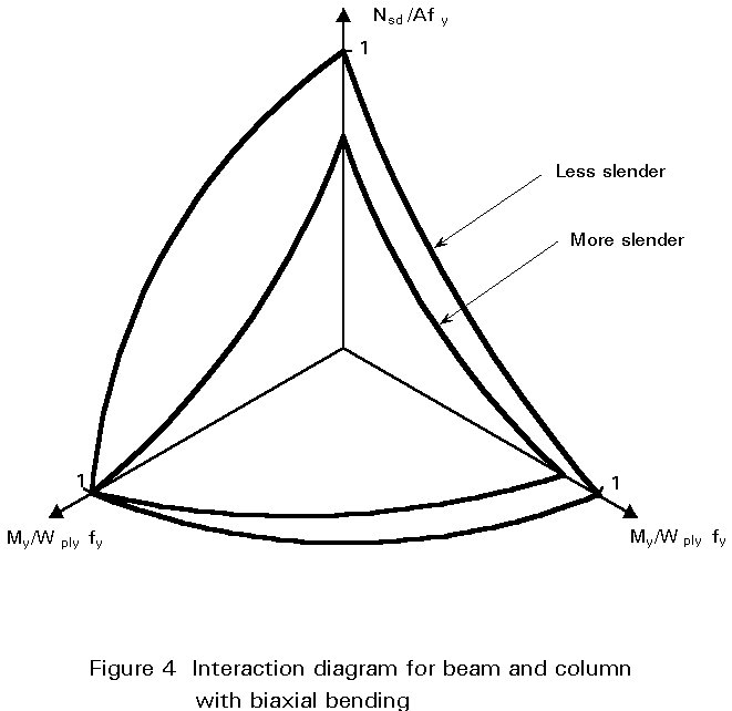
Figure 5 gives an example of a portal frame with tapered columns and beams, the external flanges of which are laterally supported by the purlins which, due to their flexural stiffness, also provide torsional restraint; the beams and columns may, however, be subject to distortion of the cross-section, due to the flexibility of the web.
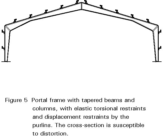
An accurate verification of this arrangement should be based on a finite element model which takes the above effects into account. The basic assumptions made regarding the imperfections in this model, would be such that the standard verification given in Section 2 would produce equally favourable results since the standard procedure has been calibrated against test results.
A more simplified procedure is, therefore, given here which is related to the verification of columns for flexural buckling, and beams for lateral-torsional buckling.
The basic principles governing the standard verification of columns for flexural buckling, and beams for lateral-torsional bucking, are as follows:
![]() FB
= Ö{Npl/Ncr);
FB
= Ö{Npl/Ncr); ![]() LT
= Ö{Mpl/Mcr)
LT
= Ö{Mpl/Mcr)
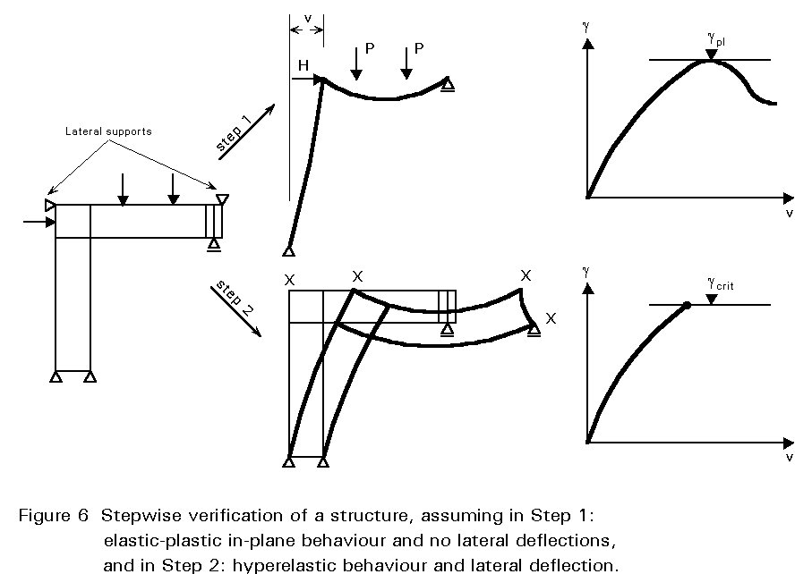
where Npl, Mpl are the characteristic values of the elastic/plastic resistances of the column or beam neglecting any out-of-plane effects; and Ncrit, Mcrit are the critical bifurcation values for the column resistance, or the beam resistance, when considering out-of-plane deflections and hyperelastic behaviour in the equilibrium state.
Nbd = c Npl / gM1 for the column
Mbd = c Mpl / gM1 for the beam.
In applying this principle to any loaded structure, see Figure 6, the procedure is as follows:

and by using the reduction coefficient c from the relevant European buckling curve, e.g. curve c, the final safety factor:
g = c gpl
can be derived.
This procedure is analogous to the Merchant-Rankine procedure for the non- elastic verification of frames.
In general the procedure described in Section 3.2 needs a computer program that performs a planar elastic-plastic analysis of the frame and determines the elastic bifurcation load of the structure for lateral and torsional deflections, including distortion. Such a program, for calculating the elastic bifurcation loads, can either be based on finite elements or on a grid model where the flanges and stiffeners are considered as beams and the web is represented by an equivalent lattice system that allows for second order effects; such programs are available on PC's.
[1] Eurocode 3: "Design of Steel Structures": ENV1993-1-1: Part 1.1: General rules and rules for buildings, CEN, 1992.
|
Moment diagram |
Equivalent uniform moment factor b M |
|
End moments |
b M,y = 1,8 - 0,7 y |
|
Moments due to in-plane lateral loads |
b M,Q = 1,3 b M,Q = 1,4 |
|
Moments due to in-plane lateral loads plus end moments |
b
M = b
m, y
+ MQ = ½ Max M½ due to lateral load only
D M = ½ Max M½ for moment diagram without change of sign D M = ½ Max M½ + ½ Min M½ where sign of moment diagram changes
|
Table 1 Equivalent uniform moment factors bM


