ESDEP WG 10
COMPOSITE CONSTRUCTION
To give an introduction to composite building structures; to describe the elements, the connections, the fabrication and the interaction of the elements; and to discuss the structural systems used.
Lecture 10.1: Composite Construction - General
Lecture 10.2: Behaviour of Beams
Lecture 10.3: Single Span Beams
Lecture 10.4: Continuous Beams
Lecture 10.6: Shear Connection
Lecture 10.8: Composite Columns
This lecture principally discusses the types of composite building structures generally used, and their methods of erection. The optimum arrangement (according to current practice) for beams and columns, is given. Different shapes of beams, and the connections of decks to beams, and of beams to columns and to walls, are discussed. Some structural details are given which exploit the shape of the structural element. The behaviour of the composite elements under seismic conditions or subject to vibrations is discussed, and the potential for further research in this field is highlighted.
The structural system of a building is a complex three-dimensional assembly of interconnected discrete or continuous structural elements. The primary function of the structural system is to carry all the loads acting on the building effectively and safely to the foundation. The structural system is therefore expected to:
In addition any structural system is usually subject to the following constraints. It should:
Steel-concrete composite systems for buildings are composed of concrete components that interact with structural steel components within the same system. By their integral behaviour, these components give the required attributes of strength, stiffness and stability to the overall system. Composite members, as individual elements of a system, have been in use for a considerable number of years. They consist of composite beams or trusses, encased or filled composite columns, and steel deck reinforced composite slabs. These members are generally used in steel structures, and their development as composite members is based on utilizing the concrete that would normally be required for floor slabs with steel beams, or that would be required for fire - protective encasements with steel columns.
In most instances, the contribution of a composite member, which is developed to support only gravity loads, has been ignored in the overall system resistance for lateral wind or earthquake loads. The development of an overall system approach, where reinforced concrete and structural steel components can be used as effective contributing parts of the whole system, is relatively recent. Considerable potential exists for evolving a variety of new structural systems in this way.
For typical structural systems used in building construction, whether they are steel, concrete or composite, there are several subsystems, or components, common to all. These sub-systems can be grouped as follows:
Section 3 discusses these systems in detail, concentrating on horizontal load resisting systems and structural connections. These topics are not covered by previous lectures.
The choice of a steel, concrete, or composite system for any particular project depends not only on system efficiency, material availability, cost, construction methods, and labour, but also on planning, architectural, and aesthetic criteria. It is thus impossible to reach definitive conclusions solely on the basis of a structural system evaluation. Section 2 describes several composite structural systems that have used successfully on commercial building projects.
Composite action between the various structural elements in a structure always exists when they are continuous (monolithic or connected by shear connectors). Depending on the size of the building, certain simplifications may be made to approximate their interaction, as isolated structural components, in a conservative manner. The use of higher strength materials and composite action are important factors in making entire systems work economically. Tall buildings require additional considerations such as slenderness, flexibility, and sensitivity to differential effects (height is not the only criterion for "tallness").
Steel and concrete are the major materials used in composite systems. Although they have several dissimilar physical characteristics, it is possible to use them together, beneficially, in different ways.
A number of systems have been developed in the last few decades which successfully combine steel and concrete. The following composite systems have been used for a wide range of buildings:
Every building, whether it is large or small, must have a structural system capable of carrying all kinds of loads - vertical, horizontal, temperature, etc. In principle, the entire resisting system of the building should be equally active under all types of loading. In other words, the structure resisting horizontal loads should be able to resist vertical loads as well, and many individual elements should be common to both types of systems.
Floor structures are responsible for a large percentage of the cost of buildings.
Floor structures can be built using elements of steel and reinforced concrete in various combinations.
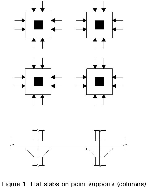
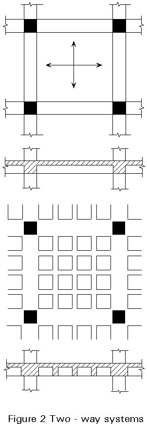
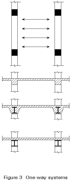
Structural floor systems are, of course, influenced by the material used, but in all cases they are a combination of slabs and joists or secondary beams (floor beams in the case of larger spacing). The characteristic element, for the whole floor structure, is the floor slab whose thickness and reinforcement is dependent upon the span, the loading and the support conditions.
In categorizing types of floor slabs, the following structural systems may be distinguished: two-way systems; one way systems; and beam and slab systems (Figures 1 - 3).
Floors take the form of concrete slabs of various types, spanning between floor beams. The types generally used are (Figure 4):
a. Precast concrete slabs which are not composite with the beams.
b. In situ concrete slabs on conventional removable shuttering, acting compositely with the floor beams.
c. In situ concrete slabs cast over thin permanent formwork/precast concrete slabs, to form a composite slab which also acts compositely with the floor beams.
d. In situ concrete slabs cast on to permanent metal decking, acting compositely with the floor beams.
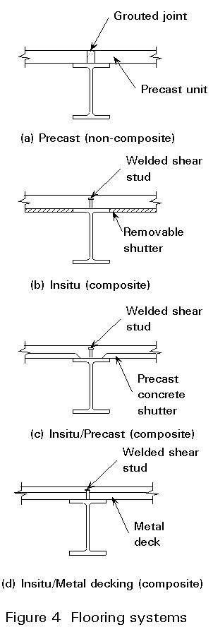
Internationally, the most widely used type includes metal decking, in which the composite action with the beam is provided by shear connectors welded through the metal decking onto the beam flange. The main advantages of this form of floor construction are the light weight of the metal decking enabling it to be manhandled easily on site, and its high stiffness and strength allowing it to support the weight of the wet in situ concrete without propping.
The spanning capability of the construction can be extended by increasing the slab depth, but this increases the weight of construction, and the depth of the floor beams. The overall depth of the floor system is therefore determined by a balance of factors. Experience has shown that the most efficient floor arrangements are those using metal decking as permanent shuttering spanning 2,5 - 3,5 m, between floor beams. For these spans the metal decking does not normally require propping during concreting and the concrete thicknesses are near the practical minimum of 120 to 150 mm (Figure 5).
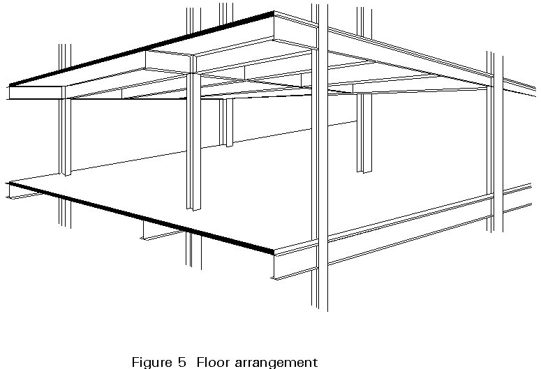
The most efficient floor plan is rectangular, not square, in which main beams span the shorter distance between columns and closely spaced floor beams span the longer distance between main beams. The spacing of the floor beams is controlled by the spanning capability of the concrete floor construction (Figure 5).
Composite beams are usually designed as simply supported, i.e. no account is taken of the moment continuity provided by the beam-to-column or beam-to-beam connections. This approach is used mainly because it gives ease of design and construction. It is also adopted partly because adequate structural performance can be achieved readily by developing composite action alone. This result certainly holds true for beam spans of 6m to 10m, which form the bulk of those currently specified.
However, there is now a strong demand for longer column-free spans in buildings, either for open-planning or to offer greater flexibility in office layout. For longer spans, the selection of the appropriate structural form is more difficult. Conventional simple construction may still be used, but often the size of the beams is such that the floor zone is excessively deep. This problem is compounded by the need to incorporate a high degree of servicing in modern buildings, most of which is located beneath the structural floor zone.
Various design solutions are feasible (see Table 1), within two basic options: either the structure and services are integrated within the same horizontal zone, or the structural zone is minimised so that the services are passed beneath. These solutions are described as follows:
a) Rolled sections
For spans in the range of 6 to 10 m, the most popular, and in many cases the most appropriate form of construction is rolled sections and simple, shear-only connections. Secondary beams at 2,4 m or 3,0 m centres support lightweight composite floor slabs, between 115 and 130 mm thickness, and span onto primary beams which in turn frame directly onto the columns.
The same form of construction may also be used for longer span floors but beam weights and costs increase to the point where other forms of construction may become more attractive.
In Figures 6 and 7 two examples are given for medium and long span.
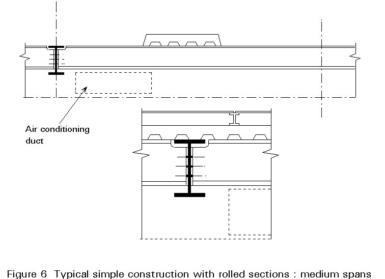

In the long span scheme the beams are of sufficient depth for the services to run through them as shown. While the design of such openings does not present any difficulty, the openings add significantly to the cost of construction. Of increasing concern to developers is the fact that web openings are an inflexible way of accommodating services, and can create difficulties in fit out for specific tenants or in subsequent reservicing during the life of the structure.
b) Fabricated sections
The potential for weight saving arises from the freedom, within practical limits, to tailor the section to suit its bending moment and shear force envelopes. Depth, taper and shape, flange size and web thickness may all be selected independently by the designer.
Fabricated sections are most likely to be economic for spans above 12m; above this span rolled sections are increasingly heavy, and a fine-tuned fabricated section is likely to show savings on both flange size and web thickness.
Where girders of constant depth are used major services may have to pass through web openings.
The various structural options for achieving the twin aims of long spans, and ready incorporation of services within normal floor zones, include:
In this method of construction, the depth of the steel beam is selected so that sufficiently large, usually rectangular shaped, openings can be cut into the web (Figure 8). For general guidance, it is suggested that the openings should form no more than 70% of the depth of the web, with horizontal stiffeners welded above and below the opening. Typically, the length of the openings should be not more than 2 times the beam depth. The best location for the openings is in the low shear zone of the beam. A step-by-step method of design has been developed to cope with the local problems which arise.

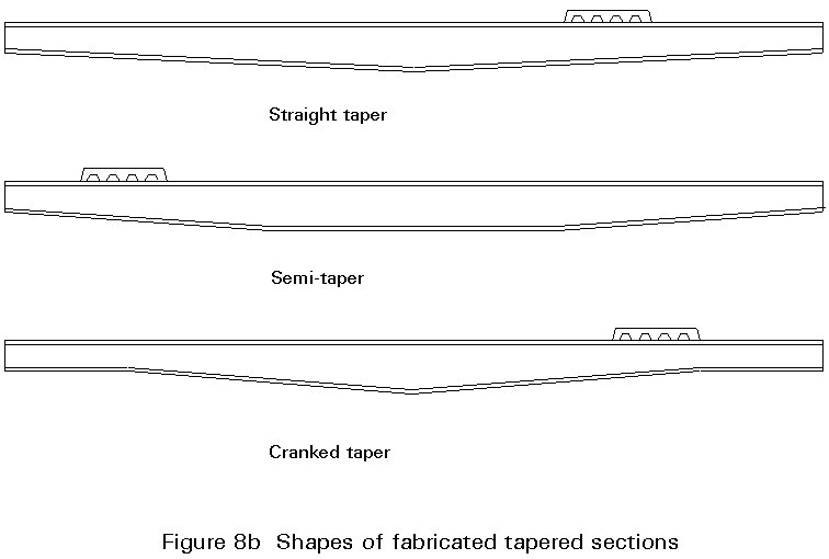
The tapered web beam is designed to provide the required moment and shear resistance at all points along the beam. The voids created adjacent to the columns can be used for modestly sized service runs. Typically, tapered beams are most economic for spans of 13 to 20 m. The plate sizes can be selected for optimum structural performance. The plates are welded in an automatic single-sided submerged arc process; thicker webs are welded by double-sided fillet welds. Web stiffeners are often required at the change of section when taper angles exceed approximately 6o. Typical tapered beams are shown in Figure 8b.
Architectural demand for square column grids with spacings of 10 to 12m led to the development of stub girder construction. The stub girder comprises a bottom chord, which acts in tension, and a series of short beam sections (or stubs) which connect the bottom chord to the concrete slab. Secondary beams span across the bottom chord and can be designed as continuous members. Voids are created adjacent to the stubs for services. This form of construction is illustrated in Figure 8c.
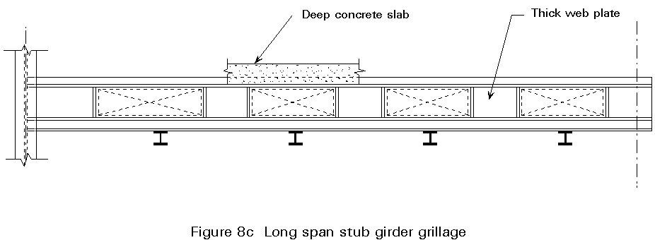
The major disadvantage of the conventional stub girder is that it requires temporary propping until the concrete has gained adequate strength for composite action. However, it is possible to introduce a light steel top chord, such as a T-section, which acts in compression, to develop the required bending resistance of the girder during execution.
Castellated beams can be used effectively for lightly serviced buildings or for aesthetic reasons, where the structure is exposed. Composite action does not significantly increase the resistance of the beams but increases their stiffness (Figure 9).
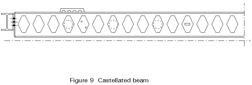
Castellated beams have limited shear resistance and are best used as long span secondary beams or where loads are relatively low.
Their primary use has been as long-span roof beams, their attractive shape often being expressed architecturally. Their combination of high bending stiffness and strength per unit weight, with relatively low shear resistance, is ideal for carrying light loads over long spans. As composite floor beams, their usage is limited by shear resistance. It is very unlikely that they could be used, for example, as the primary beams in a grillage because the associated shears would lead either to stiffening or infilling of the end openings. Both types of strengthening increase cost to the point where other types of beam would be more economical.
Composite trusses, an established form of construction in North America, are beginning to be used more widely elsewhere. Although fabrication costs are significantly greater than in many other forms of construction they do have the following advantages.
- they do not require any special fabrication equipment. Any reputable fabricator can, therefore, be invited to tender, thus improving competition and costs.
- they offer plenty of space to accommodate services, particularly if the Warren or modified Warren layout is adopted (Figure 10).
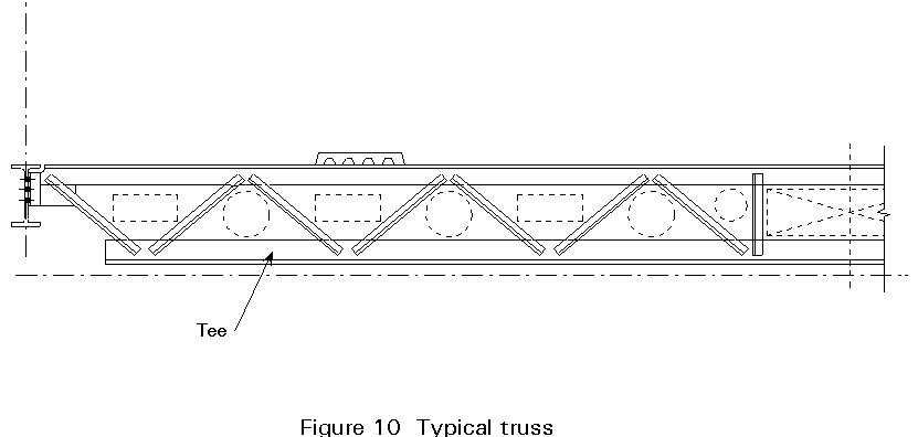
- they can be designed with a Vierendeel panel at midspan (where shears are low even under non-symmetric loading); this panel can accommodate an air conditioning duct.
The principal disadvantage, other than the increased fabrication cost, is that they are difficult to protect from fire. Sprayed protection systems are messy while the alternative of wrapping is labour intensive.
Composite trusses are only likely to be the preferred solution for spans in excess of 12m. They can readily be designed for unpropped construction. Where the truss is supporting beams, there is no local bending in the top chord and it can usually be sized just for the construction condition, making it considerably lighter than the bottom chord. Where the truss supports the composite floor slab directly, the top chord also has to be designed for bending under local loads. For economy of fabrication it is essential that the chord sections are chosen so that gussets can be avoided. Either Tee or RHS sections are usually chosen with single or double angles as web members.
c) Parallel beam approach
In contrast to many of the other solutions, it is the secondary beam that spans the greater distance in the parallel beam approach. A very simple form of construction results as secondary beams run over the primary beams and achieve continuity without complex connections. The primary or spine beams also achieve continuity simply by being used in pairs, each passing either side of the columns; shear is transferred into the columns by means of brackets. This "offset" construction, shown diagrammatically in Figure 11, where members are laid out in the three orthogonal directions deliberately to miss each other, enables continuity of the beams to be achieved without the high cost of moment resisting connections. This arrangement improves structural efficiency and, of particular importance for long span construction, stiffness. Beam lengths are limited only by handling and transportation requirements. The number of components is significantly lower than for conventional construction. As a result both erection time and cost are saved. Because continuity is such an integral part of the approach, it is primarily applicable for multi-bay layouts.

Superficially, this approach appears to lead to deeper construction. However, because of continuity, the primary and secondary beams can both be very shallow, relative to the spans, and overall depths are comparable to those in conventional construction. Most importantly, the separation of the two beam directions into different planes creates an ideal arrangement for the accommodation of services. Both major and minor services can share the same portion of the floor zone as the beams to which they are parallel, with vertical cross-overs between the two directions. Ample space is obtained, even for total air-conditioning, with a comfortable loose fit between structure and services.
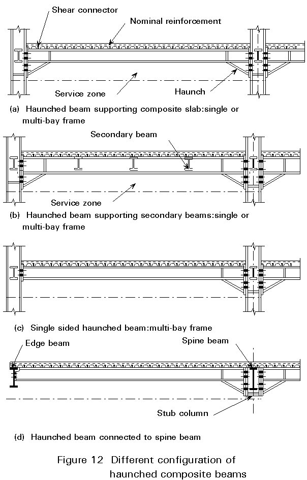
d) Haunched beams
In traditional multi-storey steel frames, the conventional way to achieve economy is to use "simple" design. Beams are about 20% heavier compared to a rigidly jointed frame but columns are typically 40% lighter, and connection costs are significantly reduced. This "heavy beam/light column" structure makes economic sense when the weight of the beams is similar to that of the columns.
Haunched beams are generally designed by forming a rigid moment connection between the beams and columns. The depth of the haunch is selected primarily to provide an economic method of transferring moment into the column. The length of the haunch is selected to reduce the depth of the beam to a practical minimum. The extra service zone created beneath the beam between the haunches, offers flexibility in service layout.
At edge columns, it would not be normal practice to develop additional continuity through the slab reinforcement; this, however, is an option at internal columns. This form of construction can be used for sway frames, i.e. where vertical bracing or concrete shear walls or cores are not provided, and is practical for buildings up to 5 storeys in height. Examples of haunched composite beams are shown in Figure 12.
Where the structure is braced against side-sway, and "plastic" sections are used, it is possible to analyse the structure plastically for the ultimate limit state. Beams can be sized on the basis of negative moment hinges at the inner ends of the haunches, which should be minimised in length to reduce column bending. Where haunched beams are being used as part of a sway frame (a form of construction for which they are ideal) elastic global analysis should be used. The art of design of elastic/plastic sway frames has still not advanced to the stage where it can be carried out in the design office. Use of elastic analysis will increase weights substantially compared to a plastic analysis. The resulting increased stiffness will assist sway stiffness and critical load factor as well as vertical stiffness, deflection and floor vibration response.
e) Prestressed steel beams
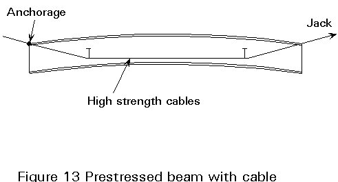
Essentially these beams work, in composite construction on the principle of inducing an initial prestress condition which later counteracts that due to the service load.
Prestressing can be achieved in three ways: prestressing components with high-strength tendons, "preflex" beams, and hybrid beams prestressed internally.
Prestressing of steel beams is achieved with high-strength tendons or cables in two ways: (1) by placing them below the centre of gravity of the beam and attaching them to the beam at its end, which results in constant prestress; or (2) by draping the tendons along the length of the beam (Figures 13 and 14).

Figures 15 and 16 illustrate a method of prestressing, whereby a steel beam is first deflected, after which a concrete slab is cast against the beam. In the top view the jacking forces are applied in a downward direction, to a steel beam which has been cambered upward. In the bottom view, a concrete slab is cast composite with the lower portion of the beam, and following curing the jacking forces are removed. This action induces compressive forces in the concrete. This method has been patented (preflex system).

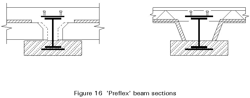
In the case of prestressed steel hybrid beams, the tension is applied to a high-strength cover plate to induce the desired prestress into the remaining portion of a beam made of medium-grade structural steel. The prestress is applied by welding the high-strength plate after stressing it directly or by deflecting the remaining beam. Both techniques cause the beam to be prestressed after release of external load. The main advantage of such prestressing is that it permits more efficient use of hybrid sections, within the Code limitations and specifications for elastic design of homogeneous members (Figures 17 and 18).


There is no Code of Practice for these types of prestressed beams.
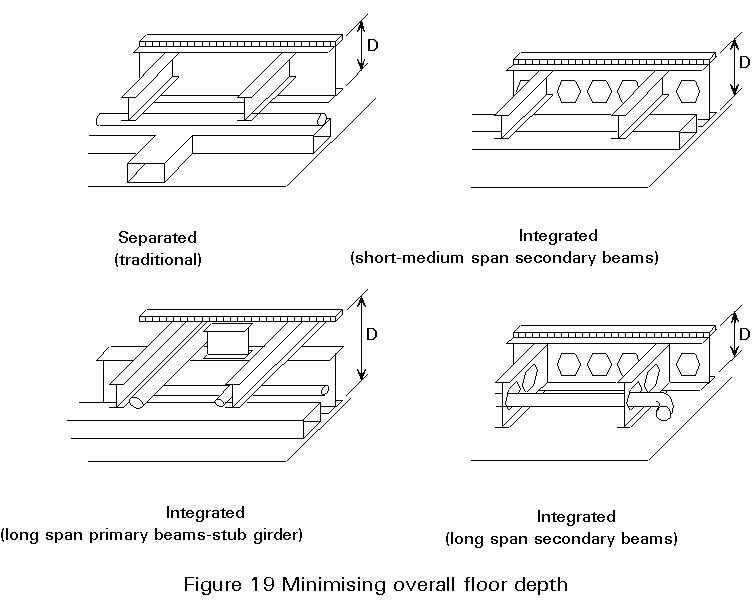
The maintenance of overall structural floor depth within a building, is an important objective in simplifying the coordination of the mechanical and electrical services and the building finishes. For the range of structural grids used in conventional buildings, traditional steel floor construction is generally deeper than the equivalent reinforced concrete flat slab. The difference is generally 100-200mm for floor structures which utilize composite action and greater for non-composite floors. The increased depth is only at the beam position: elsewhere, between beams, the depth is much less and the space between them is usable for services, particularly if the beams can be penetrated. The greater depth of steel construction does not necessarily result in an increase in building height if the services are integrated within the building zone occupied by the structure. However, integrated systems requiring numerous and irregular penetrations through the beams, may cost more to fabricate. Figure 19 shows possible solutions for integrated systems which overcome this difficulty.
Depth may be reduced, however, by utilizing rigid or semi-rigid, rather than simple connections at the end of the beams. Such connections allow the beam-bending moments to be more uniformly distributed and the beam deflection to be reduced.
The depth may also be reduced by using higher-strength steel, but this is only of advantage where the element design is controlled by strength. The stiffness characteristics of both steels are the same. Hence, where deflection or vibration govern, no advantage will be gained by using higher quality materials.
Table 1 gives some assessment criteria for the principal structural schemes that use composite beams. Most of these criteria are based on direct experience or they are the outcome of design studies. Thus they are not exclusive and it is possible to work outside these ranges.
An important characteristic of a building is the relative importance of the lateral load-resisting and stabilising systems. The normal lateral loads are those due to wind and earthquake. The columns of a tall building must be stabilised, or laterally supported, by a lateral bracing system. The lateral bracing system must resist deformations associated with the out-of-straightness and out-of-plumb of the structural members and the deformation associated with lateral forces (P-D effect).
For low and medium-rise structures, analysis and design generally involves checking the vertical load-resistant system for its ability to resist lateral forces.
In broad terms there are three fundamental types of lateral resisting elements:
The three fundamental elements are generally in vertical planes and may be placed in one or more of three locations: (1) Exterior (perimeter); (2)interior; and (3) core. Most building structures include several of these elements. The first two types are relevant to composite construction, and are now discussed:
Composite frames may consist of steel beams rigidly connected to concrete columns, or concrete beams rigidly connected to steel columns. However, the term composite has normally been applied to frames where the beams or columns, or both, as individual members, are of composite concrete and steel construction.
In a steel-frame system, the girders along column lines function as part of a continuous frame, so that reverse bending and consequently negative moments due to gravity and lateral loads are included.
A more feasible form of an unbraced composite-steel frame uses the normal construction of a rigid frame, with uncased composite beams, and reinforcement in the negative moment areas. Shear studs are provided over the entire beam length to develop moment resistance in the positive and negative moment regions of the beam.
Composite braced frames may be of two types: (1) Steel diagonal bracing may be added to a concrete frame or, much less often, concrete diagonal bracing may be added to a steel frame; and (2) composite steel and concrete linear members may be used as elements of the frame. The flexibility of a braced frame includes the deformation of the columns and beams, as well as diagonal braces that are part of the frame. If a steel column is encased in concrete, a reduction in deflection of the braced frame may be achieved. If concrete is cast around the beam, or if the beam is made composite with the floor slab, the reduced deformation of the beam will reduce the deflection of the braced frame. Concrete encasement of both columns and composite floor beams has been commonly used.
Composite columns may consist of either: (1) Concrete encased structural steel shapes; or (2) Concrete filled tubular steel sections.
Concrete encased steel columns are common. The concrete encasement has often been considered as only fire and corrosion protection for the steel. However, in recent years, lateral and sometimes longitudinal reinforcement has been added to the concrete encasement, and the resultant strength of the steel and concrete interacting has been used for structural purposes. A steel shape, encased in concrete, may be thought of as reinforcement for the concrete.
Concrete-filled tubular steel columns have been popular for use as individual column elements. The confined concrete fill increases the axial load resistance but has little effect on the flexural resistance. For that reason, it is unlikely that these columns would be a good choice for a moment resisting frame.
The beam-to-column connections play an important part in the overall stability of any frame. They should be simple, with as much work as possible performed in the workshops, thereby minimising sitework. For economic reasons these connections are generally made with bolts. On rigid frames the beam-to-column connections are made using high-strength friction grip bolts, or alternatively they are welded.
In general, these connections have evolved from connections developed for steel framed structures and are designed using similar procedures.
The main problem in designing a composite beam to steel column connection, is in assessing the behaviour and contribution of the slab to a joint that is mainly under horizontal loading. When gravity loading alone is applied to a frame, positive bending moment usually develops at midspan, and negative moment at the ends of the beams. Therefore, it is customary to assume that composite action takes place only in the positive moment region of the beam. However, when lateral loads are subsequently applied, the total bending moment at the windward end of a beam may change its sign, and the structural behaviour of the beam may suddenly change at the column line. When such a positive moment region develops next to a column, the compression in the concrete side of the composite beam is transmitted primarily by bearing on the column face and partly by torsion of the transverse beams.
Johnson and his colleagues reported results of tests on certain types of semi-rigid joint (Figure 20). This joint differs from conventional semi-rigid joints in several ways. The continuous longitudinal reinforcement in the slab is placed close to the column. High-strength friction grip bolts are used at point G in the joint, to resist a force F in longitudinal compression. The joint must be designed not to slip at point G when subject to service loads, so if high-strength bolts are not used then packing may be required at H. The bolts that connect the angle to the column flange are designed to carry the total vertical shear. The composite beam is designed as continuous, using simple plastic theory. Shear connectors are provided to transfer the force F from the slab to the steel beam. The tests showed that this type of semi-rigid joint has a well defined flexural resistance and a much greater rotation capacity than a rigid joint.

The characteristics of these connections meet general requirements for economic construction and are summarised as follows:
a) Cheap to fabricate and straightforward to erect on site.
b) Capable of behaving as a hinge during the connecting of the floors.
c) Rigid up to a certain predetermined moment.
d) Capable of rotating at the predetermined moment.
e) Capable of transmitting shear to the column while undergoing this rotation.
Another type of semi-rigid connection is shown in Figure 21. Other cases are described below.

The behaviour of a composite beam to encased column connection, appears to be that of a composite beam to steel column connection. However, the concentration of slab stress near the column flange may be lower.
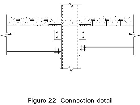
Connections to both exterior and interior columns of building frames were investigated. The rolled beams were attached to the steel column core by plated and welded joints (Figure 22). A satisfactory connection is obtained when the steel beam is fully welded to the column flange. Since the beams are subjected to negative moment, the concrete slab is in tension and cracks early in the load history. Above the cracking load, the longitudinal slab reinforcement contributes to composite behaviour.
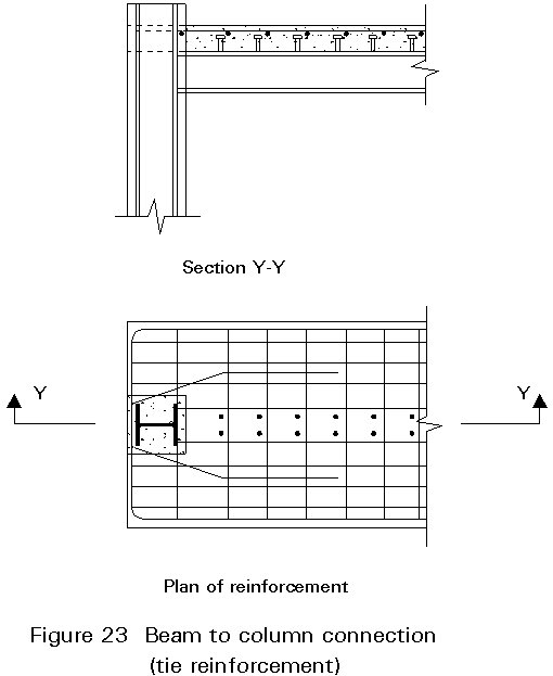
At interior columns, satisfactory composite behaviour is achieved in the beams when the longitudinal reinforcement consists simply of straight continuous bars. At exterior columns, slab failures occur when the straight bars are cut off at the end of the slab. Satisfactory behaviour is obtained when the bars are anchored externally to a heavy cross bar, or when the reinforcement arrangement in Figure 23 is adopted.
Beam-to-column joints in buildings are usually made by welding, because such rigid connections are easily designed.
Diaphragms are usually needed to prevent local deformation near to flange connections, because the concrete encasement cannot completely prevent it. Since a large diaphragm often hinders pouring of concrete into columns, several types of stiffeners, shown in Figure 24, have been used.

In typical designs, most of the bending moment in a beam is carried by the steel section and the rest by the reinforced concrete. In a column, however, the share of moment in the steel section is smaller than for a beam. This distribution results in a larger steel section for the beam than for the connected column. In this case there arises the question of whether the stresses in the steel beam section can be transferred safely to the connected column. According to tests, at least 40% to 50% of the bending moment in a column must be resisted by the steel section. If the column steel section is too small to carry this percentage of the moment, a special detail is needed.
The main problem with a composite beam to reinforced concrete column connection is to find an effective device for anchoring the steel beam into the reinforced concrete column.
A series of tests was carried out on composite beams framing into exterior columns of reinforced concrete. These tests have shown that an effective connection between a composite beam and a reinforced concrete column can be obtained, provided due allowance is made for large anchorage stresses. The horizontal forces, forming the beam couple, were transmitted to the column with varying degrees of success: by natural bond between the steel beam flanges and the concrete, with or without shear connectors; by anchorage bars; and by a "hammerhead" or short piece of beam embedded in the column. The vertical shear force, assumed transmitted through the beam web as a vertical force to the column, did not appear to contribute to any of the failures.
Shear connectors within the joint, should be used only when sufficient axial load is present to counteract the splitting stresses they induce. Horizontal anchor bars, initially unstressed, should be used mainly in connections to a continuous column, or when the moment of inertia of the column is large compared to that of the beam; this requirement also applies to vertical anchor bars. Details are shown in Figures 25 and 26.


Connections can also be achieved by corbels formed on concrete columns or walls, see Figure 27.
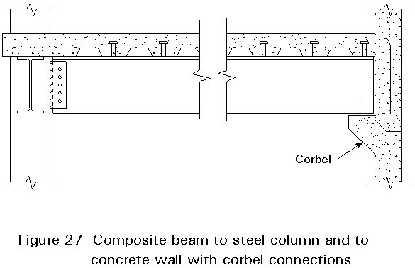
Special attention must be given to the connections between the structural steel and the concrete. When designing these connections proper allowance must be made for the construction tolerances allowed in both the steel and concrete. Adjustability must be carefully worked out to prevent site problems without becoming excessively expensive. The use of weld plates cast in the concrete, with field welded connection angles has proved most advantageous in many instances. Pockets are often used when stresses are almost purely vertical, but they tend to disrupt wall reinforcement and usually require filling with concrete. In connecting steel to concrete, the use of header beams, running parallel and close to the wall, is often desirable to reduce the number of concrete to steel connections. Moment connections and connections not absolutely required should be avoided.
The same conclusions may be drawn for steel beam to encased column connections as for composite beams to encased columns. However, in this case the moment transmitted is the plastic moment of the bare steel section. The rotation is limited by buckling of the compression flange.
In a steel beam to concrete filled tube column connection, it is important to prevent brittle fracture caused by local deformation. It was found that infilled concrete gives a large beneficial effect by reducing the local deformation of steel tubes. Diaphragms cannot be placed inside the tube because they would interfere with placing the concrete. Therefore, the stiffeners are usually placed around the outside of the tube. The effective stiffener is assumed to be a ring composed of the stiffener and a part of the tube.
Beam-to-column connections are subjected to high shears when a multi-storey structural frame undergoes severe lateral translations such as those imposed by strong earthquake ground movements. In structural steel frames the connection panel zones usually have to be reinforced to resist shear. In the case of concrete encased structural steel, however, no special shear reinforcement is usually necessary in the connection panel zone. This reinforcement is not required because the shear strength of the concrete in the panel zone is comparatively large, even though diagonal tension cracks form in that region at relatively low loads.
Properly designed connections are most important in ensuring safe and economical precast concrete encased steel structures.
The forces and deformations to be resisted by the connections arise from gravity loads, and from lateral loads due to wind and seismic forces. Joints must have enough ductility to undergo the expected deformations. The effects of member volume changes due to creep, shrinkage and temperature; the effects of differential column shortening and settlements; and the effects of fabrication and construction tolerance errors, must also be considered.
Loads for connection design require careful consideration. Moreover, it is recommended that important joints have enough resistance to transmit the full resistances of adjoining members. The design forces on joints between prefabricated frame elements can be established as accurately as the design forces on joints of cast-in-situ reinforced concrete frames. However, the design forces between panel elements are not as well established, so the lateral load coefficient for designing panel elements must be larger than the coefficient for frame elements.
The construction methods typically used for composite structures have many advantages, both in terms of economy and performance, as follows:
In buildings, composite action results in a more rigid, stiffer structure and the encasement of columns can help provide fire protection.
Although the principles of composite construction do not vary in terms of application, the construction techniques and the applied loads influence its use.
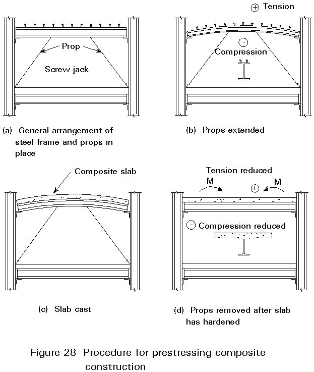
A good example of the advantages of composite construction is the use of prestressed steel, especially in buildings where there are limitations on depth. In such structures temporary props are set up from columns to cause prestressing of the steel beams above. The props are removed after the concrete hardens, which reduces the loading on the steel members allowing a reduction in depth and resulting economy. Figure 28 illustrates this construction technique.
A similar method was described by Dziewolski, using the bars acting as inclined jacks, which are attached to the upper part of the beam, see Figure 29.

Many different construction methods are used in different countries and many of the methods are patented.
Seismic design of a building structure requires that all parts of it respond nearly simultaneously when subjected to ground motion. Therefore, when earthquake forces must be considered, their effects on all building components must be evaluated. In evaluating these effects, it must be remembered that earthquake motions are random, and occur both horizontally and vertically.
The earthquake response of steel and composite building structures is a subject of much interest, because local buckling of the compression flange is inhibited (by the shear connection between the steel and concrete slab), and resistance to lateral buckling is greatly increased. Furthermore, concrete-filled tubes and encased rolled sections possess much higher shear resistance than reinforced concrete columns of the same size. High shear resistance is very important for seismic structures, as is ductility at connections, which can also be readily achieved using composite beams and columns.
Research, which needs to be continued and broadened, has shown clearly that encased steel sections in reinforced concrete, are particularly beneficial for earthquake-resistant design. However, very few studies are available, at present, on the suitability of other types of composite structural systems for earthquake-resistant design.
Shallower beams imply greater flexibility. Although the in-service performance of composite beams and floors is good, the designer may be concerned about the susceptibility of the structure to vibrations induced by the activities within the building. The parameter commonly associated with this effect is the natural frequency of the floor or beams.
A lower limit of 4 Hz (cycles per second) is a commonly accepted lower bound for the natural frequency of each floor beam. This limit has been used in Design Tables. The mass of the floor is taken as its self weight and that of ceiling and finishes, and 10% of the imposed loading. Partitions, which increase the damping of the structure, are not included.
The natural frequency, fr, of the floor or beam may be determined from the approximate formula fr = 18/Öd where d is the instantaneous deflection (mm) resulting from the self weight of the floor (including the above additional loads). A 10% reduction in deflection may be made to account for the increased dynamic stiffness of the composite beam.
In practice, the mass of the floor structure is normally such that the exciting force is small in comparison, and the response of the structure is correspondingly small. In many circumstances it can be demonstrated that the natural frequency of the floor system (primary and secondary beams and composite slab) could be reduced to 3 Hz.
The fire resistance of composite beams is assessed in the same manner as for non-composite beams. According to some codes of practice, the limiting temperature of the steel section can be established. This temperature is used in determining the required thickness of fire protection. It is traditional practice to seal the voids created by the deck above the top flange of the beam. Sealing may not be necessary for dovetail profiles.
|
Scheme |
Likely Span Range |
Economic and practical maximum ratios of: Span/Structural depth
|
Ability to contribute to sway resistance |
Accommodation of major services |
Indicative density of floor steelwork for column grids |
Estimated unit cost index for fabricated and erected steelwork |
|||||
|
Maximum X-sectional area for 15m span m2 |
Flexibility of layout across span |
Looseness of fit |
|||||||||
|
As primary beams |
As secondary beams |
||||||||||
|
6m x 12m |
9m x 15m |
||||||||||
|
Simple Construction with Rolled Sections |
6-10,5 |
8-18 |
20 28 |
Possible |
1,7 - |
Good |
Poor if web openings used |
26 |
40 |
1,0 1,3 with reinforced openings |
|
|
Fabricated Sections |
Above 12 |
Above 12 |
15 25 |
Possible if not tapered |
(Tapered) 1,9 0,9 |
(Tapered) Near column lines only |
Fair |
20 |
29 |
1,2 |
|
|
Haunched Beams |
Above 12 |
Above 12 |
25 32 |
Good |
5,3 3,6 |
Anywhere away from column line |
Good |
23** |
28** |
1,3 |
|
|
Parallel Beam Approach |
Spines up to 10,5 |
Ribs up to 15 |
21* 30 |
14* 18 |
Not developed |
5,0 2,8 |
Good |
Good |
25 |
38 |
0,9 |
|
Castellated Sections |
N/A |
Up to 16 |
17 20 |
Possible |
1,5 1,3 |
Near mid-span only if posts removed |
Fair |
27 |
38 |
1,3 |
|
|
Stub Girders |
10-15 |
N/A |
13 16 |
Possible |
3,0 2,5 |
Good |
Good |
N/A |
41 |
1,4 |
|
|
Composite Trusses |
Above 12 |
Above 12 |
12 16 |
Possible |
1,5 1,0 |
Near mid-span only for Vierendeel panel |
Fair |
22 |
30 |
1,5 |
|
* Secondary beams only
+ Including main beams
** Column weights also increased due to additional moments
Table 1: Assessment of principal structural schemes for composite floors.