
ESDEP WG 10
COMPOSITE CONSTRUCTION
To introduce composite columns, to describe their behaviour and to explain the design method for axially loaded composite columns.
Lecture 7.2: Cross-Section Classification
Lecture 7.3: Local Buckling
Lectures 7.10: Beam Columns
Lecture 10.2: Behaviour of Beams
Lecture 10.6.1: Shear Connection I
Lecture 10.8.2: Composite Columns II
The different types of composite columns are introduced and their advantages summarised. Methods of fabrication are described together with the typical connection details used at column/beam junctions. The simplified design method for an axially loaded column, given in Eurocode 4 [1], which involves the use of buckling curves, is explained and the restrictions to its application outlined; rules are also given to ensure local buckling does not cause premature failure. The influence of the long-term behaviour of the concrete, i.e. creep and shrinkage, is also considered.
In the 1960s, intensive research work commenced on the assessment of the resistance of columns in which a steel cross-section acts together with surrounding concrete. These columns could not be designed at that time by the rules for steelwork or by those for concrete structures. The result of this research work was described in various publications and led, in 1979, to design recommendations for composite columns [2].
These recommendations, together with further research work, have been used in Eurocode 4 [1], which deals with composite construction in buildings.
Eurocode 4 defines the general requirements for the design of composite columns. However, if all the geometrical and physical non-linearities of the different materials are observed, it is only possible to meet the code requirements using numerical methods of analysis. These methods can generally only be performed using a computer. Eurocode 4, however, also gives a more practical simplified method which is the subject of this lecture.
Figure 1 shows typical cross-sections of composite columns together with the dimensional notation used in Eurocode 4 [1]. The sections can be classified into two groups:
All cross-sections are symmetrical about both axes and in addition can be reinforced.
There are many advantages associated with the use of composite columns: small cross-sections, for example, can be designed to withstand high loads; similarly, sections with different resistances, but identical external dimensions, can be produced by varying steel thickness, concrete strength and additional reinforcement. Thus the outer dimension of a column can be held constant over a number of floors in a building, simplifying architectural detailing. Economic efficiency also results from the use of concrete - a low cost material - and from the time saved by using the highly developed connection techniques of steelwork construction.
With concrete filled profiles (Figure 1 d-f), the steel section serves as formwork during casting. Concrete filled sections, therefore, provide the opportunity to erect the steel frame of a building and afterwards fill the cross-sections by pumping in the concrete. By so doing the time of erection can be reduced.
The protective steel casing also allows the concrete to achieve greater strength; in the case of concrete filled circular hollow profiles, for example, the effect of confinement by the steel leads to an increase in overall resistances. The influence of creep and shrinkage of the concrete can usually be neglected for these sections. However, this influence must be considered for concrete encased profiles (Figure 1a-c).
The complete encasement of the steel section by concrete (Figure 1a), generally fulfils the technical requirements for high classes of fire protection without any additional measures. For partly encased sections (Figure 1b and c), as well as for concrete filled sections, these requirements can be achieved using additional reinforcement. Partly encased sections have the advantage that they can be produced quite simply by casting the concrete whilst the steel section lies horizontally; 24 hours later the column can be turned around and further concrete added, the formwork to the wet concrete being provided by the steel profile. For sections similar to that shown in Figure 1b the tendency for the concrete to drop out while turning the column must be avoided by suitable means, such as stud connectors. Another important advantage of these partly encased sections is that there is still a considerable area of steel available for connections, even after concreting.
Structural steel within the scope of Eurocode 3 [3], and concrete and reinforcement within the scope of Eurocode 2 [4], may be used for composite columns.
For the common steel grades, the nominal values of strength are given in Table 1. They are valid for material thicknesses not greater than 40mm. For higher material thicknesses the strengths must be reduced according to Eurocode 3.
The strengths of the different concrete grades, according to Eurocode 2, are given in Table 2. The classification C25/30 gives the cylinder strength (25) and the cube strength (30).
Eurocode 2 mentions 3 different classes for reinforcing steel, which are given in Table 3.
For design the characteristic strengths must be reduced to design strengths by material safety factors gM.
The material safety factors for the concrete and the reinforcement are taken from Eurocode 2. The safety factor for the steel is taken from Eurocode 3, which includes a safety factor g RD applied if the member may become unstable. This factor is also applied to composite columns, but only for the steel part of the cross-section.
Instability of steel parts, in composite columns, need not be taken into account if:
with Ncr given by Equation (10) and ![]() by Equation (9).
by Equation (9).
In considering the influence of long-term load effects on the compressive strength, the concrete strength in conventional concrete structures is normally reduced by the factor a = 0,85 in accordance with Eurocode 2. This reduction can be neglected for concrete filled composite sections (a =1,0) since the concrete has higher strength due to its isolation from the atmosphere and because splitting under load is prevented.
In the ultimate limit state, the attainment of the full design resistance is normally assumed for all parts of the section. However, it must be ensured that premature failure of the thin parts of the cross-section, due to instability, cannot occur.
For those exposed parts of the steel section this form of instability can be prevented by using a limiting ratio of wall dimension to wall thickness. In Eurocode
4 [1] these limiting ratios are given in terms of e = ![]() . Table 4 gives the equivalent ratios for different yield strengths.
. Table 4 gives the equivalent ratios for different yield strengths.
If the section comes within these limits the resistance of the cross-section can be determined assuming plastic stress distributions. Redistribution of moments (plastic hinge method) is not allowed, as sufficient test results concerning the rotation capacity of composite columns are not yet available.
For completely encased steel parts, verification of local buckling resistance is not necessary. For larger steel parts, e.g. flanges in Figure 1a, sufficient concrete cover must be provided in order to avoid splitting of the concrete. The minimum concrete cover in this case must not be less than 40mm or 1/6 of the dimension of the steel part. For cross-sections according to Figure 1a it follows:
40 mm £ cz ³ b/6 (1)
If exposed steel elements exceed the values given in Table 4, special methods of analysis, which are not covered in this lecture, have to be applied.
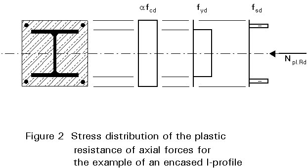
The plastic resistance of the cross-section of a composite column is given by the sum of its component resistances:
Npl.Rd = Aa fyd + Ac afcd + As fsd (2)
where
Aa, Ac and As are the areas of the structural steel, the concrete and the reinforcement, respectively.
fyd, fcd and fsd are the corresponding design strengths of each material.
a
is 1,0 for concrete filled cross-sections and 0,85 in all other cases.Figure 2 shows the stress distribution on which Equation (2) is based.
For concrete filled circular hollow sections the increased resistance of the concrete due to the confining effect of the steel tube may be taken into account. This restraint to transverse strain results in a three-dimensional stress distribution in the concrete which increases the resistance. At the same time, circular tensile stresses in the tube arise which reduce its normal resistance.
This effect may only be considered up to a relative slenderness of £ 0,5 (where is given by Equation 9). In addition, the eccentricity of the normal force, e, may not exceed the value d/10, d being the outer dimension of the tube.
The eccentricity, e, is defined by:
![]() (3)
(3)
where
MSd is the maximum design moment from the loads without considering second order effects.
NSd is the design normal force
The plastic normal resistance of these cross-sections may be determined from:
Npl.Rd = Aah2fyd + Acfcd {1 + h1[tfy/(dfck)]} + Asfsd (4)
where
t is the wall thickness of the circular hollow section.
![]() (5)
(5)
and
![]() (6)
(6)
Linear interpolation is permitted for various load eccentricities e £ d/10, with the basic values h10 and h20 depending on the relative slenderness :
h10 = 4,9 - 18,5![]() + 17
+ 17![]() 2
but h10 ³ 0
(7)
2
but h10 ³ 0
(7)
h20 = 0,25(3 + 2![]() )
but h20 £ 1,0
(8)
)
but h20 £ 1,0
(8)
Table 5 gives the basic values h10 and h20 for different values of
![]() .
.
If the eccentricity e exceeds the value d/10, or the relative slenderness exceeds the value 0,5 then h1 = 0 and h2 = 1,0.
The relative slenderness, ![]() ,
for the determination of the load-bearing resistance of a column under axial load is given by:
,
for the determination of the load-bearing resistance of a column under axial load is given by:
![]() (9)
(9)
where
Npl.R is the cross-section resistance, for normal force, according to equation 2 or Equation (4) with ga = gc = gs = 1,0.
Ncr is the elastic buckling load of the column.
Ncr = (EI)ep2/le2 (10)
where
(EI)e is the effective bending stiffness.
le is the buckling length of the column.
The buckling length of a column can be determined according to Eurocode 3 [3]. For isolated columns in non-sway systems, the column length may be considered as the buckling length.
The effective bending stiffness is determined in a similar way to the plastic resistance to a normal force, i.e. by adding up the individual components:
(EI)e = EaIa + 0,8 EcdIc + EsIs (11)
where
Ia, Ic and Is are the moments of inertia for the structural steel, concrete (here assumed as uncracked) and reinforcement, about the axis of bending being considered.
Ea and Es are the moduli of elasticity of structural steel and reinforcement.
0,8 EcdIc is the effective bending stiffness of the concrete part.
Ecd = Ecm / gc (12)
where
Ecm is the secant modulus of the concrete according to Eurocode 2 [4], see Table 2.
The material safety factor gc can be reduced to gc = 1,35 for the determination of the effective bending stiffness, according to Eurocode 2.
For slender columns, the influence of the long-term behaviour of the concrete (creep and shrinkage) on the resistance has to be considered.
If the normal force eccentricity, according to Equation (3), is more than twice the cross-section dimension, the influence of creep and shrinkage on the bending moment distribution caused by increasing deflections is so small that it may be neglected and creep and shrinkage need no longer be considered. This approach is also valid if the slenderness
![]() is less than the limiting values given in
Table 6.
is less than the limiting values given in
Table 6.
If necessary, the influence of creep and shrinkage can be taken into account by a simple modification of the modulus of elasticity of the concrete Ecd to Ec¥ :
Ec¥ = Ecd ![]() (13)
(13)
where
NSd is the design normal force.
NG.Sd is the permanently acting part of it.
It should be noted that, when assessing the importance of creep and shrinkage using Table 6, the value of d is as follows:
![]() (14)
(14)
The factor d represents the contribution of the structural steel to the normal force resistance. For concrete filled cross-sections the limit values are only applied to the concrete part (1-d).
For each of the principal bending axes of the column it must be shown that:
![]() (15)
(15)
where
Npl.Rd is the cross-section resistance for axial load (see Section 5).
c
is the reduction factor from the appropriate buckling curve.Figure 3 shows the European buckling curves for composite columns:
curve a for concrete filled hollow profiles
curve b for partially and completely concrete encased I-profiles with bending about the strong axis of the steel cross-section
curve c for partially and completely concrete encased I-profiles with bending about the weak axis of the steel cross-section
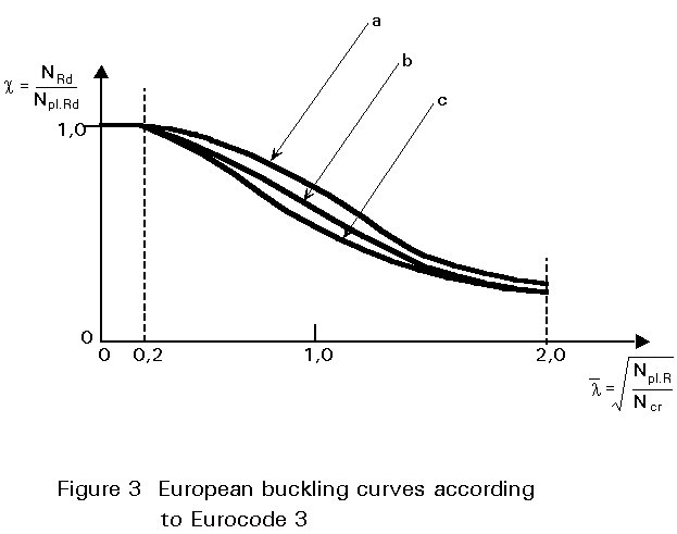
These curves can also be described mathematically as follows:
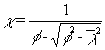 but c £ 1,0 (16)
where
![]() (17)
(17)
The factor a is used here to allow for imperfections in the cross-sections. Table 7 gives the value of a appropriate for each buckling curve.
The application of the design method described above, is subject to various restrictions. To enlarge the scope of the method, further investigations and tests on composite columns are necessary.
The maximum slenderness of composite columns is limited to:
![]() (18)
(18)
The steel contribution ratio d, according to Equation (14), must satisfy the requirement:
0,2 £ d £ 0,9 (19)
If d is less than 0,2 the column may be designed according to Eurocode 2 [4]; if d is larger than 0,9, design must be done on the basis of Eurocode 3 [3].
If the longitudinal reinforcement is considered in design, a minimum of 0,3% of the concrete area must be provided. The maximum percentage of reinforcement in the concrete cross-section, which can be used in the analysis, is 4%. For fire protection higher percentages of reinforcement can be provided, but may not be taken into account in the design, according to Eurocode 4 [1].
![]() (20)
(20)
Concrete filled sections may be fabricated without any reinforcement. For concrete encased sections longitudinal reinforcement may also be omitted; in this case only surface reinforcement is necessary.
Steel fabric reinforcement may be used as links.
The minimum value for the concrete cover of completely encased profiles is given by Equation (1). The maximum cover to the steel profile is also restricted. As with the percentage of the reinforcement, the cover may be greater but cannot be taken into account in design:
40 mm £ cz £ 0,3 h (21)
40 mm £ cy £ 0,4 b (22)
In load bearing regions it has to be ensured that the individual components of the cross-section (concrete and steel) are loaded according to their resistances, so that no significant slip between them occurs.
Header plates can be used in single-storey columns; these represent the ideal form of load introduction. Steel collars are welded onto the sides of concrete filled profiles, onto which the flange of the crossing beam may be fixed after concreting.
For continuous composite columns special detailing for load transfer is necessary. The connections shown in Figure 4 have proved economical and efficient for this purpose. Figure 4a shows details of headed studs in the webs of I-profiles. This arrangement promotes additional load transfer, which increases the resistance of the connection. The introduction of gusset plates, punched through the steel section into concrete filled hollow profiles (Figure 4b), activates three dimensional stresses in the concrete and increases the resistance of the connection.
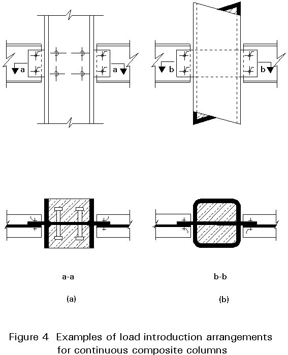
The design of these load-bearing regions, as well as design for compression and bending in composite columns, is described in Lecture 10.8.2.
[1] Eurocode 4: "Design of Composite Steel and Concrete Structures": ENV1994-1-1: Part 1.1: General rules and rules for buildings, CEN, 1992 (in press).
[2] CEB-ECCS-FIP-IABSE Joint Committee, "Draft Model Code for Composite Structures", September 1979.
[3] Eurocode 3: "Design of Steel Structures": ENV1993-1-1: Part 1.1: General rules and rules for buildings, CEN, 1992.
[4] Eurocode 2: "Design of Concrete Structures": ENV1992-1-1: Part 1.1: General rules and rules for buildings, CEN, 1992.
|
Steel grades |
Fe 360 |
Fe 430 |
Fe 510 |
|
fy [N/mm2] |
235 |
275 |
355 |
|
Ea [kN/mm2] |
210 |
210 |
210 |
Table 1: Nominal values of strength fy, and moduli of elasticity for common types of structural steel according to Eurocode 4; material thicknesses not greater than 40 mm.
|
Concrete grades |
C20/25 |
C25/30 |
C30/37 |
C35/45 |
C40/50 |
C45/55 |
C50/60 |
|
fck [N/mm2] |
20 |
25 |
30 |
35 |
40 |
45 |
50 |
|
Ecm [kN/mm2] |
29 |
30,5 |
32 |
33,5 |
35 |
36 |
37 |
Table 2: Characteristic cylinder strength fck, and mean values of the secant modulus Ecm for the different concrete grades according to Eurocode 2 [4].
|
Reinforcing steel grades |
S 220 |
S 420 |
S 500 |
|
fsk [N/mm2] |
220 |
420 |
500 |
|
Es [kN/mm2] |
200 |
200 |
200 |
Table 3: Characteristic strengths fsk, and moduli of elasticity Es for reinforcing steel according to Eurocode 2 [4].
|
Steel grade |
Fe 360 |
Fe 430 |
Fe 510 |
|
Concrete filled circular tubes lim d/t |
90 |
77 |
60 |
|
Concrete filled rectangular hollow sections lim h/t |
52 |
48 |
42 |
|
Partially encased I-sections (see Figure 1) lim b/tf |
44 |
41 |
36 |
Table 4: Limiting wall dimension to thickness ratios to prevent local buckling.
|
|
0,0 |
0,1 |
0,2 |
0,3 |
0,4 |
0,5 |
|
h 10 |
4,90 |
3,22 |
1,88 |
0,88 |
0,22 |
0,00 |
|
h 20 |
0,75 |
0,80 |
0,85 |
0,90 |
0,95 |
1,00 |
Table 5: Basic values h10 and h20 for evaluating the effect of confinement in concrete filled circular hollow sections
|
Braced and non-sway systems |
Unbraced and sway systems |
|
|
Concrete encased cross-sections |
0,8 |
0,5 |
|
Concrete filled cross-sections |
|
|
Table 6: Limit values of ![]() for considering creep and shrinkage.
for considering creep and shrinkage.
|
European buckling curve |
a |
b |
c |
|
Imperfection factor a |
0,21 |
0,34 |
0,49 |
Table 7: Imperfection factor a for the buckling curves according to Eurocode 3 [3].