ESDEP WG 10
COMPOSITE CONSTRUCTION
To describe the types and behaviour of shear connectors and to explain the load transfer between the concrete slab and steel section.
Lecture 10.2: The Behaviour of Beams
Lecture 10.3: Single Span Beams
Lecture 10.4.1: Continuous Beams I
Lectures 10.5: Design for Serviceability
Lectures 10.6: Shear Connection II and III
The forces in a typical composite beam are reviewed and their action on the connectors is described. Several basic forms of connectors are introduced and thereafter the lecture concentrates mainly on the most commonly used of these - the welded shear stud. Design values for ultimate strength and their experimental evaluation will be covered together with the weld qualification tests used to ensure quality control. Full connection is explained together with the use of reductions of connector strength by recourse to moment interaction diagrams. The use of uniformly spaced connectors and the use of through-deck welding is discussed.
This lecture deals with the way that forces are transferred between the concrete slab and steel section in composite beams. The forces are discussed together with the various types of connectors commonly used. The most common form of connector - the welded shear stud - is described in detail and methods for predicting stud resistance and stiffness are compared. The resistance, stiffness and spacing of the connectors affects the behaviour of the beam and these aspects are also discussed. The use of through-deck welded connectors in composite deck floors is also covered together with alternatives such as shot fired connectors or preloaded high strength bolts.
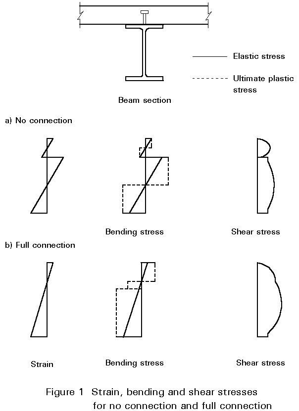
In the preceding lectures it has been assumed that the concrete and steel were fully connected together (full connection). If there is no connection then the concrete slab and steel section slide relative to one another and the bending stresses in the section are as shown in Figure 1a.
Clearly, if longitudinal shear resistance is provided by some form of connection, so that the stresses at the interface of the two materials are coincident, then the beam acts as a fully composite section. If it is assumed that the fully connected composite beam acts in an elastic way then the shear flow (shear force per unit length) between the concrete slab and the steel section may be calculated from:
T = ![]() (1)
(1)
where
V is the applied vertical shear force at the point considered.
I is the second moment of area of the section.
S is the first moment of area of either the concrete slab or the steel section about the elastic neutral axis.
Figure 1 also shows the elastic shear stress developed in the section for the conditions of both full and zero connection.
It can be seen, from the above equation, that the longitudinal shear forces that must be carried by the connection will vary depending upon the vertical shear present. Figure 2a shows the distribution of longitudinal shear, along the interface between the steel section and slab, for a beam that has a rigid full connection. It must be remembered, however, that this applies only when the beam is assumed to be behaving in an elastic manner. As the ultimate moment of resistance is reached, the steel section or concrete slab will yield or crush and a plastic hinge will form at the critical section. The bending stresses in the beam are as shown in the dashed lines of Figure 1; the distribution of longitudinal shear in the beam also changes and the connectors close to the hinge are subject to higher loads. The dashed line, in Figure 2a, shows the plastic distribution of shear force along a uniformly loaded beam.
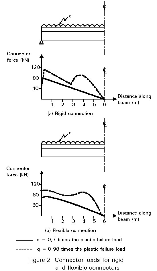
In practice, connectors are never fully rigid, and there is always some slip between the slab and the steel section. The flexibility of the connectors allows more ductility and a variation in the distribution of longitudinal shear between slab and steel section. The longitudinal shear force present in a composite beam with flexible connection is shown in Figure 2b.
At ultimate load, when the plastic hinge has formed, it is likely that the end connectors will have deformed to a considerable extent and yet still be expected to carry a high longitudinal shear load. Hence the requirement that shear connectors must have substantial ductility to perform adequately.
In determining the resistance of the beam, it is assumed that all the connectors, even when deformed, will be capable of resisting a longitudinal shear force. It is this shear resistance of the connectors that determines the resistance of the beam. If sufficient connectors are provided to withstand the longitudinal shear force generated when the full plastic resistance of the beam is developed, the beam is said to be "fully connected". It is also possible, as described in Lecture 10.2, to reduce the amount of connection so that the moment resistance of the beam is limited accordingly; this is a resistance criterion and the beam is termed "partially connected".
The slip that occurs as the connectors deform has a profound effect upon the stiffness of the beam. Very flexible but strong connectors may allow high bending resistance but because of the substantial slip there will be a loss of stiffness. The stiffness of the connection, in relation to the stiffness of the steel section and concrete slab, is often termed the interaction. Consequently, a beam where the connectors are infinitely stiff is said to have "full interaction" and one where the connection is relatively flexible is said to have "partial interaction".
It may be deduced that the strength and stiffnesses of both connector and concrete will affect the connection.
The major force acting on the connector is one of direct shear. The shear force is generally assumed to be greatest at the level of the weld between the steel section and the connector itself. The area and shear strength of the connector and weld must, therefore, be adequate to carry the forces generated. It is unlikely that any substantial deformation will take place due to this shear.
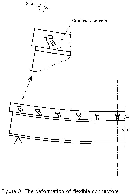
However, relative movement between the slab and steel section does occur. The mechanism for this movement can be seen in Figure 3. The concrete may crush at the connector base allowing some deformation of the connector itself. However, at the head of the connector the confining concrete is not so highly stressed and this part of the connector remains in its original position. The result is bending deformation in the connector, which can be seen clearly in Figure 3. Long connectors are more likely to deform into this characteristic "S" shaped pattern and therefore tend to be ductile. Short stocky connectors tend to be brittle and are therefore undesirable. Most codes of practice require stud connectors to be at least three or preferably four times longer than their diameter.
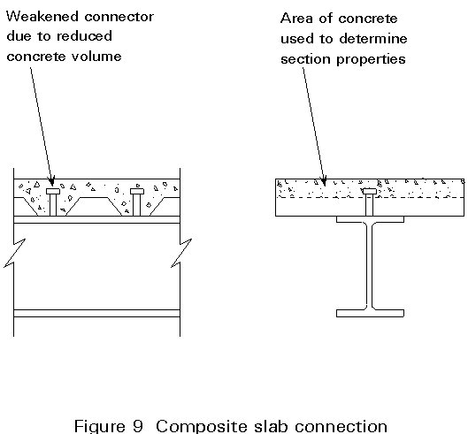
The major force resisted by the concrete is one of bearing against the leading edge of the connector. It has already been mentioned that the concrete in this region is likely to crush allowing bending deformation to occur in the connector. The bearing resistance of the concrete in this region is dependent upon its volume as well as strength and stiffness. In fact, where there is sufficient concrete around the connector, the bearing stress may reach several times the unconfined crushing strength of the concrete.
There is also likely to be direct tension in the connector. The different bending stiffnesses of the slab and the steel section, coupled with the deformed shape of the connectors, gives rise to the tendency for the slab to separate from the steel section. It is, therefore, usual for connectors to be designed to resist this tensile force.
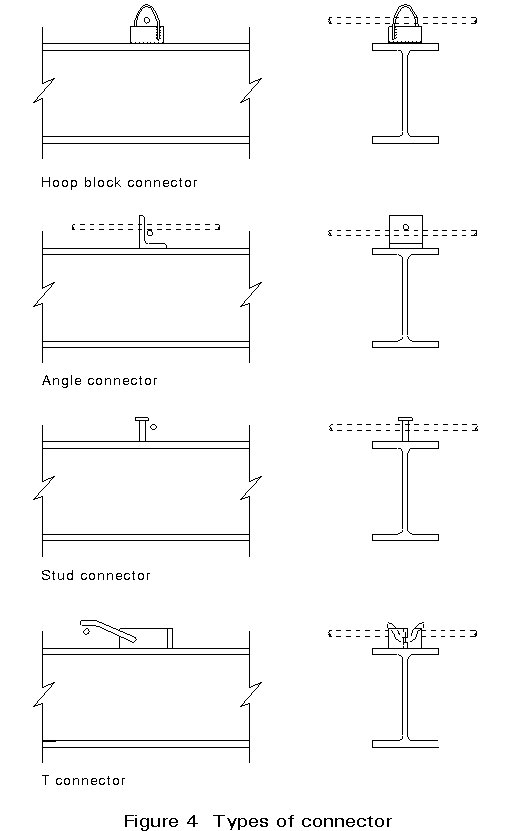
In most composite beams the connectors are spaced along the steel section and, therefore, provide a resistance to longitudinal shear only locally to the top flange. The longitudinal shear force must, therefore, be transferred from the narrow steel section into the much wider slab. This transfer is normally achieved using bar reinforcement that runs transverse to the beam line. These bars are normally placed below the head of the stud and extend into the slab, as shown in Figure 4.
To summarise, the connection must be capable of transferring direct shear at its base, resisting bending forces and creating a tensile link into the concrete. The concrete must have sufficient volume around the connector and be of sufficient strength to allow a high bearing stress to be resisted; bar reinforcement is often provided to ensure adequate lateral distribution of longitudinal shear.
Early forms of shear connector were shop welded, using conventional arc welding. Various forms of connector welded in this way are shown in Figure 4. The most common types are the hoop connector and T connector which serve to show the complexity of the forming and welding operation necessary. The popularity of composite beam construction has led manufacturers to develop very simple forms of shear connector such as the Perfobond strip [1].
Despite the plethora of connection types available, the shear stud connector has now become the primary method of connection for composite beams. The stud can be forge welded to the steel section in one operation, using micro-chip controlled welding equipment. These machines, operating at current settings of up to 2000 amps allow operators to weld approximately 1000 studs per day. The most advanced machines allow studs to be welded through galvanised steel sheeting. This ability has enabled the economic advantages of composite floor decks to be fully exploited. Figure 5 shows a typical shear stud before and after welding and the sequence of weld current required.
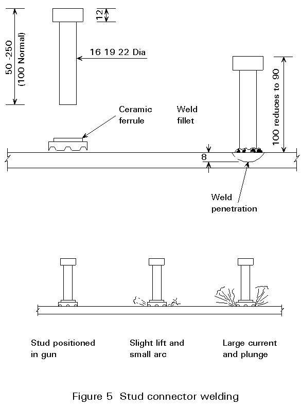
Such complex welding technology does have disadvantages when used on construction sites. The weld relies on the two surfaces being clean, free of mill-scale and, above all, dry. These conditions are often difficult to achieve especially when the studs are welded through a galvanised steel sheet; in this case, the weld current is maintained for a sufficient period to burn away the zinc galvanising, which would otherwise cause imperfect welds. Welding 22mm, rather than the more common 19mm studs, through deck also demands care. An alternative to through deck welding is to punch holes in the steel deck and then weld the studs directly to the steel section. A more reliable weld is obtained in this way but the construction process is made more complex.
The load-carrying mechanism of stud shear connectors is complex and analytical methods for predicting the shear resistance are not applicable. Instead the resistance of the connectors may be determined using empirical formulae or from tests.
The empirical formulae relate to stud and concrete resistance; the design shear resistance is therefore given by the smaller of:
PRd = 0,8 fu (pd2/4) / gv (2)
where the shear resistance of the connector is related to the tensile strength of the steel fu, using a factor of 0,8;
PRd = 0,29 a d2 Ö(fckEcm)/gv (3)
where:
d is the diameter of the shank of the stud (not greater than 22mm).
fu is the specified ultimate tensile strength of the stud material (not greater than 500N/mm2).
fck is the characteristic cylinder strength of concrete at the age considered.
Ecm is the mean value of the secant modulus of concrete.
and a is given by:
where h is the overall height of the stub,
The partial safety factor gv is normally taken as 1,25.
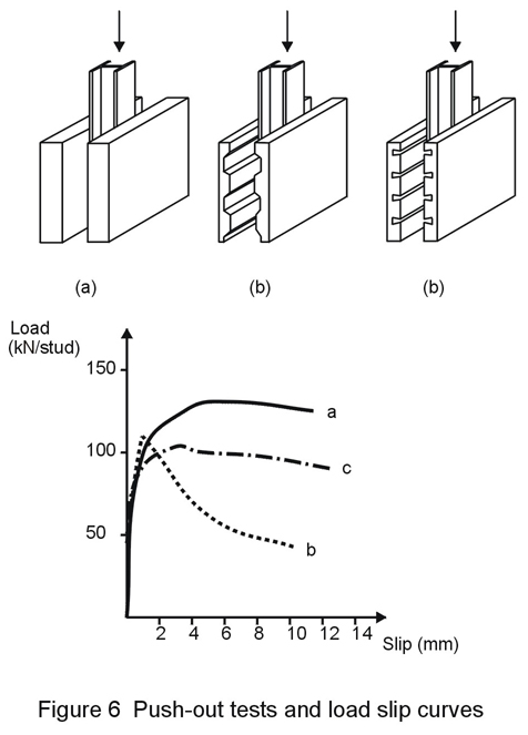
Instead of using the above formulae the designer may also obtain stud resistance values from tests. Full beam tests are expensive and a model test known as the "push-out" test is often used. This test is shown in Figure 6, together with a typical graphs of load against slip from the test. The resistance is, of course, dependent upon the concrete cube strength and is also reduced if the concrete is made from lightweight aggregate.
Shear studs carry very high loads and are normally made from drawn steel rod. Most codes quote steel properties for stud shear connectors; in addition to a high yield value the studs must be ductile and a minimum elongation is often specified. The necessity for ductility has already been explained.
The weld itself must be very well formed to ensure that the connector can carry the design loads. Elaborate weld qualification tests have been devised in America [2], to ensure that both stud and welding equipment are capable of providing consistent weld quality. Site methods of testing the weld quality are less complex, and involve bending or impact loading a certain percentage of the studs. Any studs breaking off should be replaced and further tests carried out.
In Lectures 10.2 and 10.3, it was established that, when the ultimate moment resistance of the beam is reached at a critical section, the connection is required to carry a force equal to that acting in the concrete slab between the critical section and the support. This force is the smaller of the axial resistance of the concrete slab or the steel beam. If each connector can carry a force of PRd at failure, then the total force that all the connectors can resist between the critical section and the support is:
Fc = N.PRd (4)
where
N equals the number of connectors between the critical section and the support.
Fc is the force in the concrete slab.
PRd is the design shear resistance of each connector.
The ultimate resistance of stud connectors is relatively consistent and the partial safety factor gv of 1,25 is often considered more than just a material factor. The factor has been incorporated as a result of the work of investigation of the possible results of connector failure [3]. Figure 7 shows the results of this work; in this diagram the moment resistance, expressed as a fraction of the fully composite resistance moment (as calculated in Lecture 10.3) is plotted for beams with varying numbers of shear connectors. The number of shear connectors may be expressed as a fraction of the number of shear connectors required for complete interaction (r in the figure); the value r is known as the degree of shear connection.
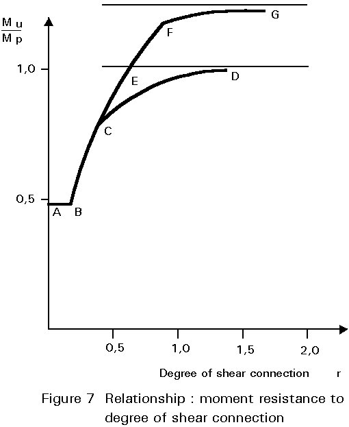
For very low degrees of shear connection the concrete contributes little to the resistance of the composite beam, and the moment resistance is that of the steel section alone (A-B). Higher numbers of connectors allow the slab to contribute more to the resistance but failure occurs as a result of connectors failing in shear (B-C). When more than approximately 50% of the connectors required for full connection are provided (r = 0,5), the beam may fail in flexure with the concrete crushing, steel yielding and the connection deforming (C-D). It should be noted that despite a flexural failure the resistance moment of the beam is less than the fully plastic resistance moment (denoted by the lower dashed line in Figure 7). The transition between shear failure and flexural failure will depend upon the ductility of the connectors. Beams formed with very brittle connectors will fail in shear even at very high degrees of connection.
In order to ensure that the full plastic resistance moment is achieved it is necessary to provide more connectors than the theoretical calculated value would suggest. It could reasonably be assumed that the fully plastic resistance moment would be achieved when the connection ratio is equal to one. However, Figure 7 shows that the connection ratio needs to be about 1,5 before this moment is approached.
If strain hardening is taken into account, the stress levels in the steel section increase, the composite beam can take a higher moment, and the interaction curve will rise to that shown on Figure 7 as E-F-G. To ensure that the composite beam failed in a flexural mode and that the fully plastic resistance moment was achieved, it has been suggested that the connection ratio should be 1,25 [3].
The graph in Figure 7 is non-dimensional and, therefore, does not depend upon the material properties of the steel section, concrete slab or shear connectors. It can be concluded, therefore, that the 1,25 value is not a material safety value, but a factor to take into account the reduction in flexural resistance that occurs as a result of connector flexibility.
If the beam is assumed to behave elastically and is being designed so that elastic stresses are not exceeded in the steel section, concrete slab or shear connection, it is preferable to space the connectors along the beam so that the higher shear loads near the supports or concentrated load positions are resisted by a closer spacing of connectors. This spacing ensures that each connector carries an equal share of the longitudinal shear force (see Lecture 10.2).
However, it is now more common to design the beam at the ultimate limit state, using factored loads and a plastic section analysis. In this case, as shown in Figure 2, the shear flow along the beam is more uniform and a uniform spacing of connectors is more appropriate.
Most beams carrying uniform loads are designed with a uniform spacing of shear connectors. For this purpose the connectors must be ductile and allow some straining associated with the relative movement between slab and steel section.
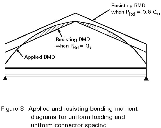
A further reason for the use of the partial factor gv, when determining the design resistance of connectors, can be seen when the uniform spacing of connectors is examined in relation to the applied moment diagram. Figure 8 shows the applied bending moment for a uniform loading and the moment of resistance generated by the beam. The major component of bending resistance is provided by the composite action and, as the shear connectors are uniformly spaced, the resisting moment varies linearly from a maximum at mid span to a minimum at the support. The shaded portions of the applied bending moment diagram are, therefore, greater than the moment resistance of the beam. If the connector resistance is assumed to be only 0,8 of its full value (1/gv), then the actual resistance moment generated will be increased sufficiently to ensure safety.
The uniform spacing of connectors makes detailing much easier but care needs to be taken if heavy concentrated loads are to be applied to the beam. In these cases connectors should be spaced broadly in accordance with the shear flow along the beam. A minimum spacing of 600mm for connectors is normally recommended to ensure that the shear flow along the beam is not too irregular.
The use of profiled steel sheeting in composite slabs has revolutionised office construction, mainly due to the ease with which "Through Deck" shear studs can be welded. There are three possible causes for concern when using this form of construction:
Although welded shear studs are the major type of connector used, there are situations where alternatives are more applicable. For example, alternatives may be preferable on construction sites where only a small number of connectors are required and the hiring of expensive generators cannot be economically justified.
An alternative in these situations, is the shot-fired connector shown in Figure 10. This connection can be fixed using modified cartridge guns which do not require any power supply. The connection itself fails when the pins pull out and is, therefore, weaker than the welded shear stud. When used in pairs these connectors can provide sufficient resistance for small beams and for beams designed with partial shear connection (see Lecture 10.6.2).
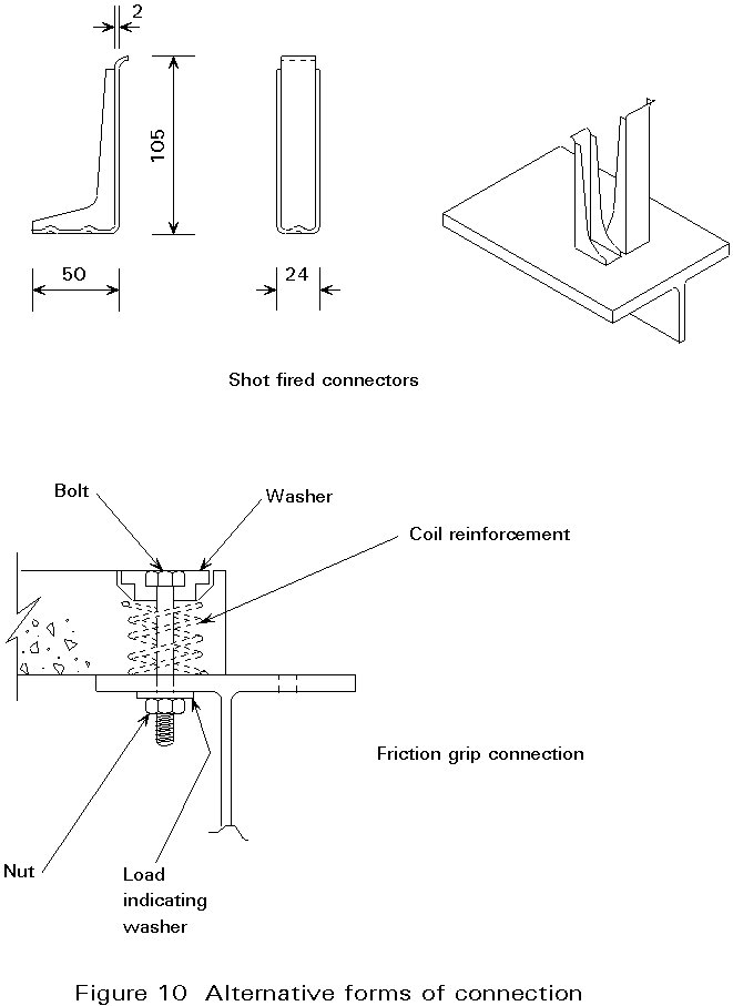
Another situation where welded connectors are inappropriate is the case where precast concrete slabs are used compositely with the support beam. In this case high strength friction grip bolts (HSFG) have been used to fix the slabs to the steel flange, see Figure 10. HSFG bolts rather than simple bolts are needed so that, at the serviceability stage, no slip between the concrete slab and steel section can take place. Consequently, for serviceability design, the slip resistance of the HSFG bolt should be used and for the ultimate moment design, the bearing or shear resistance of the bolt is used.
[1] Andra, H.P., "Economical Shear Connectors with High Fatigue Strength", Proc. IABSE Symposium on Mixed Structures, Brussels, 1990.
[2] ANSI/AWS, "American Welding Society Structural Welding Code Steel", 1985, (Appendix K) Doc. D1 1-85.
[3] Yam, L.C.P. and Chapman, J.C., "The Inelastic Behaviour of Simply-supported Composite Beams of Steel and Concrete", Proc. I.C.E., 41, 651-684, Dec 1968.