ESDEP WG 10
COMPOSITE CONSTRUCTION
To discuss, in more detail, the serviceability criteria introduced in Lecture 10.5.1; to elaborate on creep and shrinkage effects in concrete; to describe the development of cracking; and to examine, in detail, the Eurocode 4 serviceability requirements for composite structures [1].
Lecture 10.2: Behaviour of Beams
Lecture 10.3: Single Span Beams
Lectures 10.4: Continuous Beams
Lecture 10.5.1: Design for Serviceability I
Lectures 7.8: Restrained Beams
Lectures 7.9: Unrestrained Beams
The lecture provides general information on creep, shrinkage and cracking of concrete, so that the student can orientate himself towards the literature available.
Serviceability limit state design for cracking is discussed in detail using two different approaches: "Deemed to satisfy" and "Explicit" methods.
This lecture provides further background information on some of the aspects of composite construction discussed in Lecture 10.5.1. It deals, in particular, with creep, shrinkage, and cracking of concrete. It is not possible, within the confines of this lecture, to deal comprehensively with these topics - particularly that of creep; rather, it is sought to provide sufficient information to permit a student to orientate himself towards the available literature.
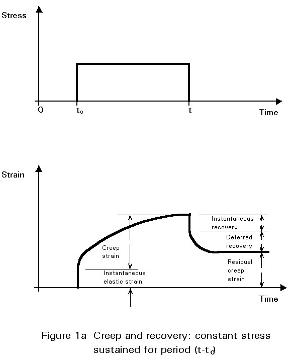
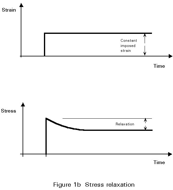
In addition to the non-linearity displayed under short-term loading (Section 2.2.2 and Fig. 1 of Lecture 10.5.1), concrete displays a time-variant response to sustained loading. The increase in strain which occurs, over time, under the action of sustained constant stress is termed creep (Figure 1a). It is to be noted that recovery, on unloading, is neither instantaneous nor complete, but comprises an instantaneous portion followed, over a period of time, by a deferred recovery. At the end of this recovery there remains a residual creep deformation. Another phenomenon, which is related to creep, is the relaxation of stress under sustained constant strain (Figure 1b).
Even in the absence of applied loading, concrete is subject to deformation due to volume changes arising from changes in water content, from long-term chemical processes occurring within the cement paste, and from thermal dilation. The most significant of these changes is shrinkage, which is the reduction in concrete volume due to loss of water by evaporation or hydration of the cement, or by carbonation. The opposite effect is the swell in concrete during hydration. Swelling of concrete is normally an order of magnitude less than shrinkage, and is not usually of concern in design.
The significance of such volume changes is due to the fact that they are usually wholly or partially restrained, and thus give rise to tensile stresses and cracking. The resulting change in stiffness will in turn influence deformations.
Creep and shrinkage are related phenomena. These delayed strains of loaded or unloaded concrete can be considered as two aspects of a single physical phenomenon.
In concrete made with normal-weight aggregates, creep occurs in the hardened cement paste, and is resisted by the aggregate. Material and environmental factors influencing creep are:
In addition, the magnitude of creep deformations is affected by age at loading, the duration of the loading, and the stress level.
The theories of creep, normally applied to concrete structures, assume creep strain to vary linearly with stress. It is a reasonable simplifying assumption for normal levels of serviceability stress.
For a detailed discussion on the factors influencing the development of creep, reference should be made to standard texts on concrete technology.
Creep is conventionally described by reference to a creep function and to a creep coefficient. The creep function, F(t, t0), refers to the total strain - instantaneous elastic and creep strain - at a given time, under the action of constant unit stress (Figure 2a). The creep coefficient f(t, t0), is the ratio of the creep component of this strain to the instantaneous elastic component (Figure 2b).
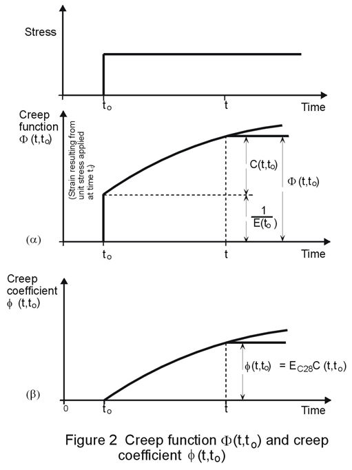
The creep function may be written as the sum of an instantaneous elastic strain and specific creep as follows:
F(t, t0) = 1/Ec(t0) + C(t, t0)
where:
or, in terms of a creep coefficient:
F(t, t0) = 1/Ec(t0) . (1 + f(t, t0))
where the creep coefficient is:
f(t, t0) = Ec(t0) . C(t, t0)
On occasion, reference is made to a 'normalised' creep coefficient, such as the creep coefficient calculated on the basis of the elastic modulus (or instantaneous strain) at 28 days and denoted f28 (t, t0). In this case:
F(t, t0) = 1/Ec(t0) + f28 (t, t0)/Ec28
where Ec28 is the elastic modulus at 28 days, and where
f28 (t, t0) = f(t, t0) . Ec28/Ec(t0)
Because creep is a complex phenomenon, there is considerable diversity in approach to the formulation of the creep function for concrete. The diversity arises from efforts, on the one hand, to model more accurately the various facets of the creep phenomenon - the effect of age at loading, the effect of load duration, the deferred aspect of response on unloading - and on the other hand, from efforts to avoid a degree of complexity in calculation which is inappropriate to the accuracy obtainable. It must be remembered that the basic creep data upon which such calculations are based will rarely be precise, and the accuracy of the calculations will reflect this imprecision. In Eurocode 2, Clause 2.5.5.1 [2] it is stated that the accuracy of the procedures for calculating the effects of creep and shrinkage should be consistent with:
Generally creep is modelled in one of two ways: on the one hand it can be modelled as the product of two functions which represent age at loading and duration of loading (the CEB-FIP recommendations of 1970, as well as the 1971 ACI Code used such a formulation); on the other hand, the creep function can be modelled as the sum of a number of components, instantaneous and time-dependent, reversible and irreversible. These components are typically:
|
instantaneous |
- elastic |
(reversible) |
|
time-dependent |
- deferred elasticity |
(reversible) |
|
|
- flow |
(irreversible) |
An additional term - for initial creep - is introduced into the CEB-FIP Model Code Method [3].
Various methods encountered in the literature are:
For a detailed discussion of these and other methods, reference should be made to the specialist literature on creep in concrete.
The approach presented in this lecture is based on Eurocode 2 [2].
The treatment of creep, given in Eurocode 2 [2], is based on linear theory, which permits superposition of the creep deformations due to stress fractions applied at different times. The proposals for creep contained in this document relate to concrete which has been allowed to harden under constant ambient conditions, and which is subjected to a compressive stress not exceeding 0,4fckj at age j. This stress limit encompasses the range of values encountered in the vast majority of concrete structures under service conditions.
In this code, creep deformation is described in terms of a creep coefficient, as already defined in Section 2.2.2.1 and total deformation in terms of a creep function. The creep coefficient corresponds to the "normalised" - f28(t, to) - value previously referred to, which for the sake of convenience, will be referred to simply as f (t, t0) in the remainder of this lecture.
In Eurocode 2 [2], the creep coefficient is expressed as a product of various components, taking the form:
f(t, t0) = fRH.b(fcm).b(t0).bc(t-t0)
The significance of each component is summarised below:
|
Component: |
Taking account of: |
|
f RH |
× relative humidity of the ambient environment |
|
b (fcm) |
× concrete strength |
|
b (t0) |
× age at loading |
|
b c (t-t0) |
× development of creep with time, after loading |
The total strain at time t due to a stress so applied at time t0 is given by:
etot (t, t0) = so.f(t, t0)
Or, in the more general case:
etot (t, t0) = en (t) + so.f(t, t0) + SsD(ti).f(t,ti)
In this expression:
e
n (t) denotes an imposed deformation independent of the stresses, e.g. shrinkage or temperature effects.Ds
(ti) denotes stress variations applied at times ti, subsequent to t0.This is sometimes expressed in a different form, incorporating an ageing coefficient, c :
etot (t, t0) = en(t) + s(t0).f(t,t0) + (s(t)-s(t0)) . (1/Ec(t0) + c .f(t, t0)/Ec28)
where the value of the ageing coefficient, c, depends on the development of strain with time. In many cases this value may be taken as 0,8.
If the stresses in the concrete vary only slightly, the deformations may be calculated using an effective modulus of elasticity:
Ec,eff = Ec(t0)/(1 + f(t, t0))
for which values of f may be taken from Table 1.
From this table it can be seen that creep is substantially greater for dry atmospheric conditions and for early age at loading.
Shrinkage is the shortening that takes place in concrete - separately from the effects of external loading or changes in ambient temperature - whilst hardening is in progress. The strain due to shrinkage, ecs, which develops in an interval of time (t-t0) is given in Eurocode 2 [2] by the following expression:
ecs (t, ts) = es (fcm) . bRH.bs(t-ts)
in which the components have the following significance:
|
Component: |
To allow for the effect of: |
|
b (fcm) |
× concrete strength |
|
b RH |
× environmental conditions |
|
b s (t-ts) |
× development of shrinkage with time |
Reference should be made to Eurocode 2 for values of these parameters. Where a less accurate estimate will suffice, the values given in Table 2 may be used.
Theories of creep and shrinkage, as developed for reinforced concrete, require adjustment before they can be applied to a composite beam. This is because of the substantial effect the steel beam has on the behaviour of the section. The difference in the effects of creep and shrinkage on a simple unpropped beam is shown in Figure 3 in terms of a modified modular ratio.
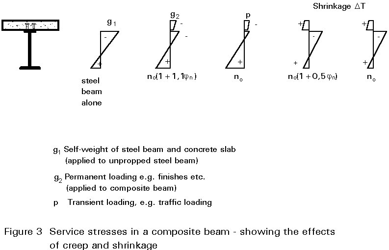
Figure 4 illustrates the effects of shrinkage on a composite beam. The concrete flange is initially allowed a shrink freely, experiencing no restraint from the steel beam (Figure 4a). A tensile force NSH is then applied to the concrete flange to restore it to its original length. The value of this force is:
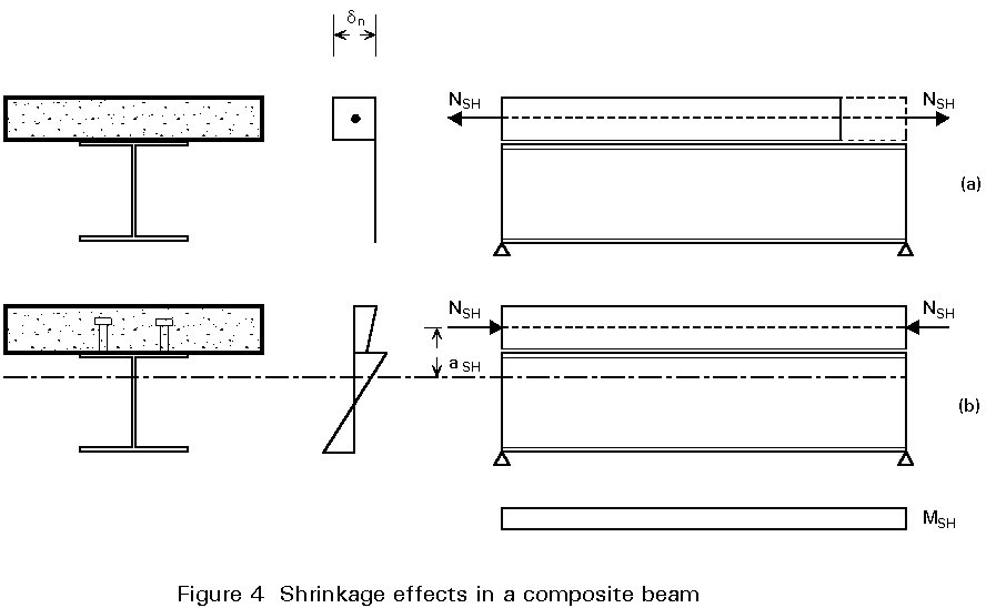
NSH = Ac.Ec.ecs (t, t0)
Assuming stresses to be in the elastic range, the stress in the concrete is then:
sc = NSH/Ac
and in the structural steel section:
ss = 0
At this stage, the composite connection between the steel beam and the concrete flange is considered to come into effect, preventing relative movement (slip) at the interface. Equilibrium is established by balancing the tensile force with an equal and opposite compressive force, -NSH, applied to the composite section. This gives rise to a bending moment MSH = NSH.aSH about the centroid of the composite section. The resulting stresses are shown in Figure 4b.
As well as being influenced by the presence of the steel beam, shrinkage effects in composite members are modified by creep; hence the different effective modular ratios shown in Figure 3 for shrinkage and for creep. The basis for the adjustment of the modular ratio is outside the scope of this lecture; for further explanation reference should be made to specialist literature on creep in concrete. For simplicity, adjusted values of n for the calculation of section properties - for use in determining the effects of creep and shrinkage - can be obtained from Table 3.
Lecture 10.5.1 introduced the concept of cracking in reinforced concrete elements. Further details are now given on the "deemed-to-satisfy" and crack width calculation approaches of Eurocode 2 [2].
Cracking in reinforced concrete may be partially or fully penetrating, depending on the nature of the stress distribution across the section, as indicated in Figure 5. The two cases shown - corresponding to flexural and axial loading - give rise to notably different stress increases in the reinforcing steel at the onset of cracking. It is important that the reinforcing steel should not reach yield at any early stage in the development of cracking (Figure 6). This condition is avoided by prescribing the minimum amount of reinforcement necessary to prevent a sudden transition to yield. This amount varies depending on the stress distribution in the concrete at cracking.
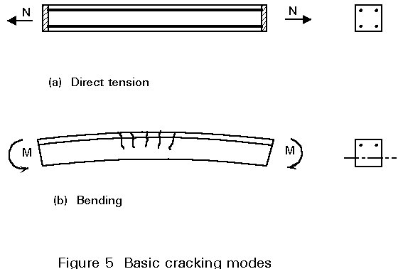
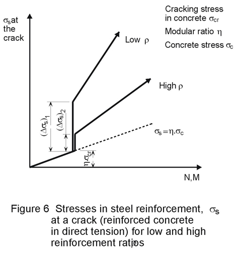
Figure 7 illustrates several aspects of cracking in reinforced concrete. There is a local loss of adhesion between concrete and steel in the vicinity of a crack; the reinforcing bar exercises a restraining effect on the crack width; the crack width at the surface is greater than that at the bar. Similarly, the surface crack width midway between two bars will be greater than on the surface adjacent to a bar. The maximum surface crack width is of significance from the point of view of appearance, whilst the value affecting durability - through ingress of moisture to the reinforcement - is the crack width adjacent to the bar.
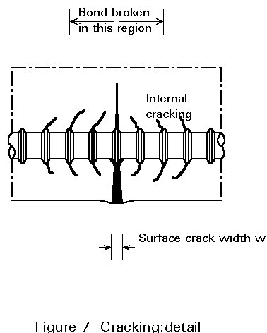
Figure 8 illustrates the stresses associated with cracking in an axially loaded member. The formation of the first crack is accompanied by a complete transfer of load from the concrete to the reinforcement at the crack, with a consequent loss of bond. There is a transitional region on either side of the crack within which, by virtue of bond, the original stress regime is gradually re-established. The bond characteristics of the materials determine the position of subsequent cracks relative to the first. The second crack is unlikely to form within the transitional region, because of the lower concrete stresses applying there. It will form at a slightly increased load, and will give rise to stress distributions of the type shown in Figure 8b.
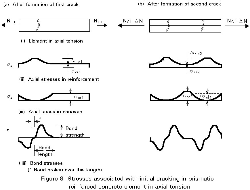
One of the effects of cracking is to neutralise the residual stresses due to shrinkage.
The effect of initial and subsequent cracking on the stiffness of a composite section is shown in Figure 9. This illustrates the tension stiffening effect of concrete in the tensile zone. A consequence of this is that the flange tensile force is higher than the value obtained using cracked section properties, which is calculated on the assumption that concrete is ineffective in tension.
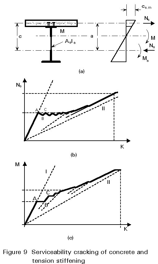
The hogging moment, M, acting on the composite section may be decomposed into a bending moment, Ma, acting on the steel section, together with a couple formed by the direct forces, Na and Ns, acting through the centroid of the steel section (compression) and of the concrete flange (tension), see Figure 9. It is common to ignore the small bending moment contributed by the concrete flange to the overall equilibrium of the section. If the distance between the centroid of the steel section and that of the concrete flange is a, then the equilibrium of the section can be expressed as follows:
M = Ma + Na.a
The response of the section is initially governed by the uncracked section stiffness, indicated by line I in Figure 9, and the tensile force in the concrete increases linearly with M up to the commencement of cracking. The loss of stiffness in the concrete flange, resulting from cracking, gives rise to an increased rotation (AB in Figure 9c) and a redistribution of forces within the composite section. The bending moment in the steel section, Ma, is increased and Ns is reduced accordingly (AB on Figure 9b). As the overall moment, M, is further increased, the value of Ns increases again (BC in Figures 9b and 9c), until such time as the cracking stress is once more attained in the concrete flange, and a further redistribution occurs.
The process repeats itself, with no significant increase in the tension flange force, and with progressive reduction of the effective stiffness of the section, until cracking stabilises. This is termed the phase of initial crack formation. It is characterised by the fact that the concrete flange force, Ns, does not exceed the tensile resistance of the section. The phase which follows shows an increase once again of Ns with increasing applied moment M. This phase, however, displays the "tension stiffening" role of the concrete, in spite of cracking. The composite section displays a greater stiffness, up to ultimate moment, than would be predicted by a calculation based on the concrete being ineffective in tension (line II in Figure 9). The consequences of this greater stiffness are reduced rotation of the section and a greater force, Ns, in the concrete flange.
Eurocode 2 provides two approaches to crack control:
In each case a specified minimum quantity of reinforcement must be provided to restrain deformations.
This section gives further details on the minimum reinforcement areas specified in Lecture 10.5.1 (Tables 5 and 6) which are required to resist the stress arising from restrained deformations.
Factors influencing the minimum reinforcement areas required by Eurocode 2 [2] are as follows:
a. The nature of the imposed deformations which are being restrained. They are categorised as:
i. intrinsic deformations - which are due to dimensional changes in the member - for example, those arising from shrinkage.
ii. extrinsic deformations - which are externally applied - for example, support settlements.
b. The type of stress distribution within the member at the onset of cracking. The distribution may be classed as due to:
i. bending - resulting in a triangular stress distribution with some part of the section remaining in compression.
ii. tension - with the whole section subject to tensile stress.
The required minimum reinforcement area is calculated from the following expression:
As = kc . k . fct ef . Act/ss
where
As is the area of reinforcement within the tensile zone.
Act is the area of concrete within the tensile zone; the tensile zone is that part of the section which is calculated to be in tension just before the formation of the first crack.
s
s is the maximum stress permitted in the reinforcement immediately after formation of the crack. This may be taken as 100% of the yield stress of the reinforcement, fyk. A lower value may, however, be needed to satisfy the crack width limits (see Tables 5 and 6, Lecture 10.5.1).fct ef is the tensile strength of the concrete effective at the time when the cracks may first be expected to occur. A minimum value suggested in Eurocode 2 is 3N/mm2 [2].
kc is a coefficient which takes account of the type of stress distribution occurring within the section immediately prior to cracking. The stress distribution is that resulting from the combination of the effects of loading and of restrained axial deformations. Values of kc are:
kc = 1,0 for pure tension.
kc = 0,4 for bending without normal compressive force.
In Table 5 of Lecture 10.5.1, values are given for the minimum reinforcement ratios (As/Act) required to control cracking arising from restraint of imposed deformations, for various levels of stress.
For limit state design, cracking in reinforced concrete is generally described with reference to a limiting crack width. In a satisfactory structure, it is to be expected that a small number of cracks will exceed this reference value under maximum loading. The limiting value will be established with reference to environmental conditions, and to the requirements of durability and appearance. With certain structures, there could be an additional performance requirement to satisfy - such as watertightness - which would determine the reference crack width to be used in design.
The crack width limitations for reinforced concrete in Eurocode 2 are specified with reference to the exposure classes listed in Table 4.1 of Part I of Eurocode 2, and relate to a quasi-permanent combination of loads [2].
For exposure classes 2 to 4, it may be assumed that limitation of the maximum design crack width to about 0.3mm will generally be satisfactory for reinforced concrete members in buildings, with respect to both appearance and durability. Where dry environmental conditions prevail (exposure class 1), the maximum design crack width does not affect durability, and the above restriction can be relaxed if this is acceptable on visual grounds.
The design crack width may be obtained from:
wk = b.srm.esm
where
wk is the design crack width.
srm is the average final crack spacing.
e
sm is the mean strain under the relevant combination of loads, allowing for the effects of tension stiffening, shrinkage, etc.b
is a coefficient relating the average crack width to the design value.The value of b is as follows:
For restraint cracking of intermediate section sizes, values of b may be interpolated.
e
sm may be calculated from the relationship:esm = ss/Es (1 - b1 . b2 . (ssr/ss)2)
where
s
s is the stress in the tension reinforcement, calculated on the basis of a cracked section, for the loading condition under consideration.s
sr is the stress in the tension reinforcement, calculated on the basis of a cracked section, for the loading condition causing first cracking.b
1 is a coefficient which takes account of the bond properties of the bars. Values of b1 are:b1 = 1,0 for high bond bars
b1 = 0,5 for plain bars
b
2 is a coefficient which takes account of the duration or of the repetition of loading. Values of b2 are:b2 = 1,0 for a single, short term loading
b2 = 0,5 for a sustained load, or for many cycles of repeated load.
The average final crack spacing for members subjected principally to flexure or tension, srm, can be calculated from the equation:
srm = 50 + 0,25 k1 k2 f /rr
where
f
is the bar size in mm.k1 is a coefficient which takes account of the bond properties of the bar. Values of k1 are:
k1 = 0,8 for high bond bars
k1 = 1,6 for plain bars
k2 is a coefficient which takes account of the form of the strain distribution. Values of k2 are:
k2 = 0,5 for pure bending
k2 = 1,0 for pure tension
Eurocode 2 provides a method for the calculation of intermediate values of k2, for use in cases of eccentric tension or for local areas [2].
r
r is the effective reinforcement ratio, As/Ac.ef, whereAs is the area of reinforcement contained within the effective tension area, Ac.ef.
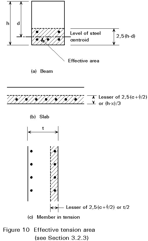
Ac.ef is generally the area of concrete surrounding the tension reinforcement, of depth equal to 2,5 times the distance from the tension face of the section to the centroid of the reinforcement (Figure 10). For slabs, where the depth of the tension zone may be small, the height of the effective area should not be taken as greater than (h-x)/3, where h is the overall depth of the concrete section, and x is the depth to the neutral axis, measured from the face.
[1] Eurocode 4: "Design of Composite Steel and Concrete Structures": ENV1994-1-1: Part 1.1: General rules and rules for buildings. CEN (in press).
[2] Eurocode 2: "Design of Concrete Structures": ENV1992-1-1: Part 1.1: General rules and rules for buildings. CEN, 1992.
[3] Comité Euro-International du Béton - Féderation Internationale de la Précontrainte (CEB-FIP), CEB-FIP Model Code for concrete structures, Paris, London, Berlin, 1978.
|
Age at loading to (days)
|
Notional size 2 Ac/u (in mm) |
|||||
|
50 |
150 |
600 |
50 |
150 |
600 |
|
|
Dry atmospheric conditions (inside) (RH = 50%) |
Humid atmospheric conditions (outside) (RH = 80%) |
|||||
|
1 |
5,4 |
4,4 |
3,6 |
3,5 |
3,0 |
2,6 |
|
7 |
3,9 |
3,2 |
2,5 |
2,5 |
2,1 |
1,9 |
|
28 |
3,2 |
2,5 |
2,0 |
1,9 |
1,7 |
1,5 |
|
90 |
2,6 |
2,1 |
1,6 |
1,6 |
1,4 |
1,2 |
|
365 |
2,0 |
1,6 |
1,2 |
1,2 |
1,0 |
1,0 |
Table 1 Final creep coefficient f(¥, t0) of normal-weight concrete
|
Location of the member |
Relative Humidity (%) |
Notional size (2Ac/u (mm) ) |
|
|
150 |
600 |
||
|
Inside Outside |
50 80 |
0,60 x 10⁻³ 0,33 x 10⁻³ |
0,50 x 10⁻³ 0,28 x 10⁻³ |
Table 2 Final shrinkage strains ecs¥ of normal-weight concrete as given in Eurocode 2
|
Age at Loading
|
Creep |
Shrinkage |
||
|
Internal |
External |
Internal |
External |
|
|
7 days 14 days 28 days 90 days |
4,5 4,0 3,5 3,0 |
3,8 3,4 3,0 2,5 |
2,8 2,5 2,2 2,0 |
2,4 2,2 2,0 1,8 |
Table 3 Effective values of the modular ratio n - for use in the calculation of creep and shrinkage effects