ESDEP WG 10
COMPOSITE CONSTRUCTION
To present serviceability criteria within a limit-state framework; to derive the elastic properties of the section; to introduce time-dependent behaviour of concrete; to discuss the factors influencing cracking and deflection in composite structures; and to outline "deemed-to-satisfy" procedures for checking cracking and deflection.
Lecture 10.2: Behaviour of Beams
Lecture 10.3: Single Span Beams
Lectures 10.4: Continuous Beams
Lectures 7.8: Restrained Beams
Lectures 7.9: Unrestrained Beams
Lecture 10.5.2: Design for Serviceability II
The criteria for design for the serviceability limit state are discussed. Elastic analysis of simply supported and continuous composite beams with respect to cracked and uncracked sections is described. Serviceability limits for cracking and deformation in an "explicit" and a "deemed-to-satisfy" approach are outlined.
In order that a structure should remain fit for use and that its appearance and durability remain satisfactory, consideration has to be given, during design, to "serviceability limit states". These limit states relate to aspects of a structure's behaviour such as cracking, deformation, and vibration, when checked under normal service conditions.
The economic consequences, for the client, of failure to satisfy serviceability criteria can prove every bit as severe as structural failure. At the least, failure to meet serviceability criteria is likely to result in increased maintenance and repair costs. In some cases it will result in a loss of utility, of durability, and ultimately, of the integrity of the structure.
Factors such as the "design life" of the structure (which can vary within wide limits) and exposure conditions will influence the design values of serviceability parameters. The classification of the "design situation" (as defined in the Eurocodes 1, 2, 3 and 4 [1-4]) as persistent, transient or accidental, will similarly, have a bearing on these values. Transient situations, which merit separate consideration from the serviceability point of view, are those which might, for example, apply during construction.
Serviceability limit state criteria may be categorised for composite structures as follows:
(a) Slip at the steel-concrete interface, when it becomes large enough to invalidate design checks.
(b) Excessive compressive stress in the concrete, leading to microcracking and affecting durability.
(c) Excessive cracking in concrete tension zones.
(d) Unacceptable deformations or deflections, which affect the appearance or efficient use of a structure or cause damage to finishes or other non-structural elements. These deformations are affected by cracking, creep and shrinkage; and by slip, where significant.
(e) Vibrations producing discomfort or affecting non-structural elements or equipment.
Within these categories, a variety of limit states may be defined, corresponding to different structural types and conditions.
Some of the serviceability requirements are satisfied implicitly - by virtue of assumptions made or restrictions introduced whilst designing the section for strength. Thus Eurocode 4 [4] requires no specific checks for compressive stresses in the concrete under service loading, and slip at the steel-concrete interface need not be checked provided the design of the shear connection is in accordance with Chapter 6 of Eurocode 4. In addition, vibration need not be considered in detail for the majority of composite elements.
The serviceability limit states, which are considered particularly in this lecture are those of excessive cracking and deformation. In the design of a composite beam for the serviceability limit state, it must be shown that under service conditions (gF = 1) the deflections (d), and the cracking of concrete (w), is limited. The design value of the effect of actions Ed shall be less than (or equal to) a limiting value Cd.
Elastic analysis is used for the calculation of Ed. (See Eurocode 4, Section 5.2 and 5.3 [4]).
Limits for deflections and cracks are given in Eurocodes 2, 3 and 4, see Eurocode 4, Sections 5.2 and 5.3 [4].
It must be shown that:
Ed £ Cd
Ed are calculated crack widths w or deflection d.
Cd are limits for crack width wlim or deflections dlim.
It is frequently the case that the length or the complexity of calculations required for the explicit satisfaction of serviceability criteria is not warranted by the accuracy obtainable. For example, the detailed calculation of deflection, taking into account creep and shrinkage, is based on values of certain parameters which are of necessity approximate: the stiffness of a cracked reinforced concrete section, for example, or the values of creep and shrinkage coefficients. A considerable degree of approximation must therefore attach to the laboriously calculated deflection.
In the present lecture simplified procedures are described for satisfying serviceability requirements. In some cases, the procedure enables the use of indirect criteria. Such simplified methods are termed "deemed-to-satisfy" methods. They are perfectly adequate for the majority of situations encountered in design, and are widely used in practice because of their greater ease of application.
Detailed consideration is given in the accompanying lecture (Lecture 10.5.2) to explicit criteria for serviceability.
The mechanical and geometrical properties of the composite section are required for the calculation of service stresses and deformations. At service stress levels, the concrete in compression and the steel are assumed to behave in a linearly elastic fashion. Where Eurocode 4 [4] permits the use of the uncracked flexural stiffness, (EI)1 (see Section 2.4), concrete in tension may be considered uncracked. Where the flexural stiffness of the cracked section, (EI)2, must be used, the strength of concrete in tension is ignored.
Even after cracking has occurred, the section derives stiffness from the concrete. This "tension stiffening" is due to the uncracked concrete between cracks. This effect is not taken into account in the calculation of section stiffness in this lecture. It is, however, taken into account indirectly in the calculation of deflections and crack widths.
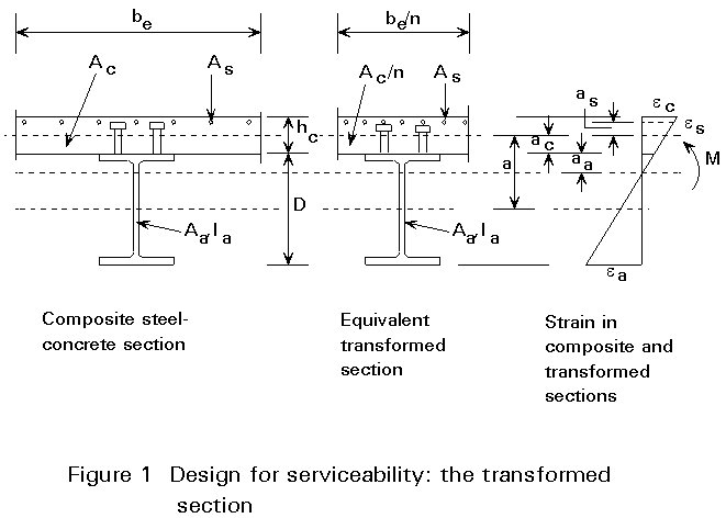
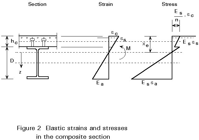
In calculating the section properties of the composite section for serviceability checks, use is made of the concept of the transformed section. Using this concept, the steel-concrete composite section is replaced by an equivalent homogeneous section in steel. For a section subjected to positive bending, the concrete flange of area Ac is replaced with a fictitious steel flange of area Ac/n, where n is the modular ratio (see Section 2.2.4). The fictitious steel flange is of similar depth to the concrete flange, see Figure 1. Geometrical properties are readily calculated for the transformed section, and strains may be obtained using the elastic modulus for steel. Use is again made of the modular ratio in calculating elastic stresses in the concrete flange of the original composite section as shown in Figure 2.
The value of the elastic modulus for structural steel, Ea, is given as 210x103N/mm2 in Eurocode 4. A value of 200x103N/mm2 is given in Eurocode 2 [2] for the elastic modulus of reinforcing steel, Es. For simplicity, the Eurocode4 value, 210x103N/mm2, is adopted in this lecture for structural and for reinforcing steel alike.
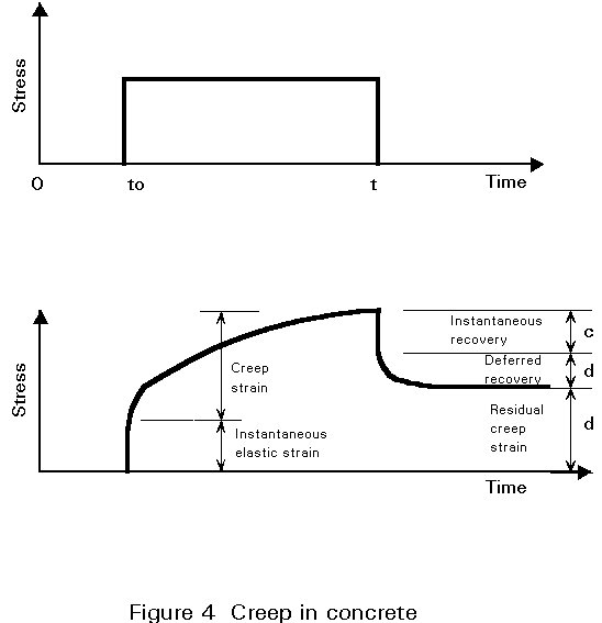
Concrete is a non-linear, non-elastic material. It does not display a unique or constant value of elastic modulus as shown in Figure 3, and sustains permanent deformation on removal of load. When subjected to a constant stress, concrete strains increase with time - a phenomenon known as creep - see Figure 4. It is also subject to changes of volume caused by shrinkage (or swelling), and by temperature changes.
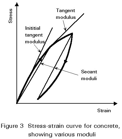
Notwithstanding this non-linearity, it is necessary to be able to quantify the relationship between stress and strain in order to obtain a realistic estimate of deformations. Various elastic moduli are shown in Figure 3. These are: an initial tangent modulus; a tangent modulus corresponding to a given stress level; a secant modulus; and a "chord" modulus. The values of a number of these moduli are seen to depend on the reference stress level. They are, in addition, affected by rate of loading. The value used in design codes is generally a secant modulus corresponding to a specified rate of loading.
An estimate of the mean value of the secant modulus Ecm for short-term loading, for normal-weight concretes, can be obtained from Table 1 for the range of concrete strengths normally used in composite construction.
Time-dependent deformation of concrete may be calculated as outlined in Section 2.2.4 below. Additional information is given in the accompanying Lecture 10.5.2, and in the relevant sections of Eurocode 2 [2].
In the calculation of the geometrical properties of the section, and of stresses, reference is made to the modular ratio, n. This is the ratio Ea/Ec, where Ea is the elastic modulus of structural steel, and Ec is that of the concrete. The effect of the modular ratio on stresses is illustrated in Figure 2.
For the calculation of long-term effects in buildings, and in bridges without prestressing or pre-cambering, sufficiently accurate results will be obtained by using an effective modulus for concrete, Ec¢ , in the calculation of the modular ratio. The effective modulus is the short-term modulus for concrete modified for the effects of creep.
Eurocode 4 [4] gives three sets of values for short-term and long-term modular ratios. These values are listed in order of increasing simplicity in Table 2. It will not usually be necessary to resort to method (a) in that table, which involves explicit calculation of the creep coefficient f. The choice of method should take account of the purpose of the analysis and the accuracy required. It is noted in Eurocode 4 that the value of the modular ratio has much less influence on the accuracy of calculated action effects than on calculated stresses or deformations. Method (c), which adopts the same high value of the modular ratio for both short-term and long-term effects, could thus be used conveniently for the global analysis of structures; this would remove the need for separate analyses for these two conditions.
More detail is given on creep in the accompanying Lecture 10.5.2.
In considering the geometric properties of the composite section for use in elastic analysis, a variety of options appear to exist, depending on:
In practice, however, it is only necessary to consider a small number of options. For the uncracked section, in positive bending, the contribution of reinforcement to the section stiffness is ignored; in any case, the quantity provided is often nominal and is generally not known at the beginning of analysis. If the uncracked section is being used in an area of negative bending, the reinforcement may be taken into account. However, the result will be that, in the initial analysis of a continuous beam, stiffness will vary along the length of the member. In order to avoid complexity in the initial analysis, therefore, it is sometimes preferred to neglect the reinforcement in such situations. For cracked sections, however, it is common to include the area of tension reinforcement.
The concepts of effective breadth and shear lag have been introduced in Lecture 10.3. Similar values are used in serviceability calculations, for both positive and negative moment regions.
The second moment of area for the sections described in Section 2.3.1 are as follows (see Figures 1 and 2):
(a) The Uncracked Section
(i) General case - including reinforcement:
Taking moments of area about the neutral axis of the steel section, with Ac = be.hc and with At = Aa + (Ac/n) + As:
(Ac/n) . a + As . (a + as) = At.aa
giving:
aa = ( (Ac/n) . a + As . (a + as) ) / At
The second moment of area of the transformed (all-steel) section is:
I = Ia + (Ac/n) . (hc2/12) + (Ac/n) . ac2 + As . (ac + as)2
(ii) Uncracked section - reinforcement excluded:
Taking moments of area about the neutral axis of the steel section, with Ac = be.hc and with At = Aa + (Ac/n), this simplifies to:
(Ac/n) . a = At.aa
giving:
aa = (Ac/n) . a / At
The second moment of area of the transformed (all-steel) section is then:
I = Ia + (Ac/n) . (hc2/12) + (Ac/n) . ac2
(b) The cracked section
Reinforcement is included in this case, and the area of concrete in tension (and its tension stiffening effect) is neglected. Taking moments of area as before about the centroid of the steel section, with At = Aa + As, then:
As . (a + as) = At.aa
giving:
aa = As . (a + as) ) / At
The second moment of area of the transformed (all-steel) section is:
I = Ia + As . (ac + as)2
The preceding values for I are used to calculate stresses under service conditions. Thus, if xe = (ac + hc/2), the concrete stresses at the top (t) fibre of the uncracked section are:
ft = M.xe/n.I
while bottom (b) fibre stresses in the steel section are:
fb = M.(D + hc - xe)/I
The service stress in the steel reinforcement is:
fs = M.(ac + as)/I
Reference is made in Eurocode 4 [4] to the following values of section stiffness:
(EI)1 is the uncracked section stiffness, where:
E is the Ea
I is the elastic second moment of area of the effective equivalent steel section, calculated using the short-term modular ratio.
Calculations are based on the assumption that the concrete in tension is uncracked, and may be taken as being reinforced or unreinforced.
(EI)2 is the cracked section stiffness, where:
E is Ea
I is the elastic second moment of area of the effective equivalent steel section, calculated using the long-term modular ratio. The area of concrete in tension (and its tension stiffening effect) is neglected, but account is taken of steel reinforcement.
In many cases, serviceability checks can be carried out without the need for a separate analysis. The required bending moments can be obtained by factoring the results of analysis for the ultimate limit state.
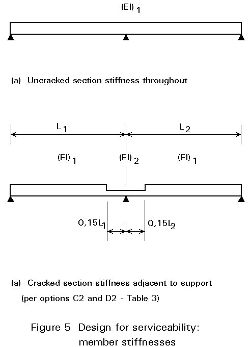
For those cases where separate analysis is required, the recommendations of Eurocode 4 regarding analytical models for cracking and deflection checks on continuous beams, are summarised in Table 3.
These analytical models are summarised graphically in Figure 5. Analysis is carried out initially assuming a uniform member stiffness (that of the uncracked section, (EI)1) throughout, see Figure 5a. If re-analysis is required, the section stiffness adjacent to supports is modified to (EI)2 as shown in Figure 5b.
In reinforced concrete, cracking of the concrete is a normal and acceptable part of its response to structural actions. The fact that much of the cracking originates in the early stages when concrete strength is low, and shrinkage and thermal strains are high, makes it very difficult to eliminate it completely. Even when mature, concrete cracks at relatively low levels of tensile strain. The restriction of tensile strains to a level at which such cracking could be avoided would entail very uneconomical use of steel reinforcement.
Fortunately, cracking need not affect the serviceability of a structure. Indeed, it can be of benefit in redistributing action effects from heavily stressed regions. Such redistribution can be used to permit the use of more economical sections. Cracking also has the effect of neutralising the residual stresses on the element due to shrinkage.
Cracking is of concern because of its potential effect on the durability and on the appearance of reinforced concrete elements. Durability is affected if cracking is sufficiently penetrating to permit ingress of moisture to reinforcement. It should be noted, however, that cover to reinforcement by porous concrete may be even more significant in this respect. In relation to appearance, the significance of cracking will obviously be related to its visibility. Visibility of cracking will vary depending on factors such as the surface texture of the concrete and its distance from possible observers. Cracks on exposed surfaces can be highlighted by streaks of dirt or by materials leaching out. In this way quite small cracks can become visually obtrusive.
The width of a crack will vary with structural actions. Crack widths arising from unusually heavy transient loading are not significant as regards durability; rather it is the effect of sustained (or "quasi-permanent") loading which is relevant in this regard. It should also be noted that cracks caused by infrequent loading will sometimes seal autogenously.
A general aim in designing for crack control is to have distributed cracking. A large number of narrow cracks is preferable to a smaller number of wide cracks.
Detailed consideration is given in Lecture 10.5.2 to the development of cracking in reinforced concrete, and to its control by the explicit calculation of crack widths. In the present lecture attention is focused on deemed-to-satisfy measures for crack control, which suffice in the great majority of cases, and which entail significantly less calculation.
Regardless of the approach adopted, correct detailing practice, in accordance with Eurocode 2, is essential for the satisfactory control of cracking.
The "deemed-to-satisfy" approach to crack control entails two steps:
(a) Where there is a likelihood of significant tension due to restraint of imposed deformation (whether or not this is combined with direct loading) a minimum amount of bonded reinforcement should be provided, sufficient to ensure that the reinforcement will remain elastic when cracking first occurs.
(b) Bar diameters and/or spacings should be limited.
The practical application of (b) above may result in the provision of more reinforcement than is envisaged in (a).
A suitable arrangement of reinforcement may be selected, as outlined below using Tables 4 and 5, which is intended to ensure that crack widths will not generally exceed 0,3mm in reinforced concrete. An explanation of the background to these tables is given in Lecture 10.5.2. It should be noted that calculation of reinforcement areas required for crack control should neglect any contribution from profiled steel sheeting. The method is as follows:
(a) Using Table 4 provide minimum steel based on ss = fyk.
(b) Using the actual area of reinforcement provided, calculate the service stress in the reinforcement, taking account of tension stiffening, as follows:
ss = ss,0 + 0,4 (fctm.Ac/As)
Then use Table 5 (column 2) to limit bar size. If it is desired to use a larger bar size, it will be necessary to reduce the service stress in the reinforcement to the corresponding level (using Table 5, column 1) by increasing the area of reinforcement.
(a) Using Table 4 provide minimum steel based on ss = fyk.
(b) Calculating the service stress in the reinforcement as at 1(b) above, use Table 5 to limit either:
× bar diameter (column 2), or
× bar spacing (column 3).
It may again be necessary, as at 1(b), to modify the area of reinforcement if it is desired to adopt a particular bar size.
It should be noted that Part I of Eurocode 4 Clause 5.3.3(3) suggests that in certain instances the minimum reinforcement may be reduced or dispensed with altogether [4].
Owing to a variety of factors, the deflections of composite elements deviate from the values which would be predicted by a simple elastic model. These factors include:
The time-dependence of certain of these factors means that the actual sequence of loading will have a bearing on the final deflections, and may invalidate simple calculation procedures based on the superposition of effects. Additionally, material properties (Young's Modulus, creep factor, etc.) which are used in analysis will depend on factors such as the actual concrete mix used, and on temperature and humidity levels during the early life of the structure.
The magnitude of final deflections may be reduced by pre-cambering or by propping. With pre-cambering, a slight curvature is rolled into the steel section, opposite in sense to that caused by the permanent loading. This deformation may be such as to counteract the deformation due to self-weight, or due to a proportion of imposed loading in addition to the self-weight of the composite element. With propping, the steel beam is additionally supported during construction, until such time as the concrete has reached a specified percentage of its characteristic strength. The propping ensures that the dead load of the concrete is taken by the stiffer composite section rather than by the steel section alone, as happens with unpropped construction. Propped construction allows the use of lighter steel sections. It is however, more susceptible to creep effects, unlike unpropped construction where the dead weight of the concrete is taken by the steel beam, and the permanent component of the remaining loading is frequently small.
In spite of the variety of parameters influencing deflections, it is usually possible to arrive at an assessment of their magnitude by relatively simple means.
In the calculation of deflections for buildings, it will normally be satisfactory to consider deflections under typical load combinations and to assume that this loading is of long duration.
The serviceability limit state is reached when a deflection reaches a limit determined by:
or other possible forms of unserviceability.
Eurocode 4 [4] requires that the calculation of stresses and deformations at the serviceability limit state should take into account the effects of (see Section 2):
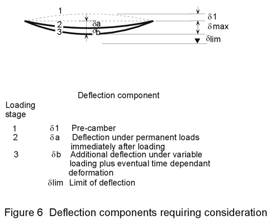
For floor and roof construction in buildings, the deflection limits recommended in Eurocode 3 [3] are as in Tables 6 and 7. These limits are expressed in terms of span or cantilever length, as appropriate. Deflection components db and dmax are illustrated in Figure 6.
In bridges, calculation of deflections is normally only necessary when:
Deflections due to loading applied to the steel member acting independently, should be calculated in accordance with Eurocode 3 [3]. Elastic analysis of the composite member can be carried out by one of the methods listed in Table 3. Factors which require consideration are summarised in Table 8, with associated Eurocode 4 prescriptions.
The serviceability limit state must be checked when designing simply supported and continuous composite beams. The main points to consider are:
[1] Eurocode 1: "Basis of Design and Actions on Structures", CEN (in preparation).
[2] Eurocode 2: "Design of Concrete Structures": ENV 1992-1-1: Part 1.1: General rules and rules for buildings, CEN, 1992.
[3] Eurocode 3: "Design of Steel Structures": ENV 1993-1-1: Part 1.1: General rules and rules for buildings, CEN, 1992.
[4] Eurocode 4: "Design of Composite Steel and Concrete Structures": ENV1994-1-1: Part 1.1: General rules and rules for buildings, CEN, (in press).
[5] ENV 206 "Concrete-Performance, Production, Placing and Compliance Criteria", CEN.
|
Strength Class of Concrete (Normal weight concrete) - per ENV206 (S.7.3.1.1) [5] |
20/25 |
25/30 |
30/37 |
35/45 |
40/50 |
45/55 |
|
|
Characteristic compressive strength - cylinder - cube |
fck fck,cube |
20 25 |
25 30 |
30 37 |
35 45 |
40 50 |
45 55 |
|
Associated mean tensile strength |
fctm |
2,2 |
2,6 |
2,9 |
3,2 |
3,5 |
3,8 |
|
Secant modulus of elasticity |
Ecm |
29 |
30,5 |
32 |
33,5 |
35 |
36 |
Table 1. Characteristic compressive strength, fck (N/mm2 or GPa), the associated mean tensile strength, fctm (N/mm2 or GPa), and the mean value of the secant modulus of elasticity for normal-weight concrete, Ecm (kN/mm2or MPa), .
|
Value of the modular ratio, |
|||
|
Option |
Short-term effects |
Long-term effects |
Comments |
|
(a) |
Secant modulus Ecm (Table 1) |
Various, depending on concrete grade |
This method takes account of concrete grade and age. |
|
(b) |
6 |
18 |
Takes account of concrete grade, but not concrete age. |
|
*(c) |
15 |
15 |
Takes no account of concrete grade or age |
*Restricted to beams, the critical sections of which are in Class 1 or 2
Table 2. Short term and long term values of the modular ratio, n, as given in Eurocode 4 [4].
|
Method Number |
Stiffness for use in elastic global analysis |
Aspects |
Comments |
||
|
Redistribution |
Re-analysis |
||||
| (a) |
CRACKING C1 C2 |
||||
|
(EI)1 throughout |
no |
no |
for general use |
||
|
(EI)1 throughout; then use (EI)2 adjacent to internal supports at which s ct > 0,15 fck, for any loading condition, and reanalyse |
no |
yes |
see note 1 |
||
| (b) |
DEFLECTIONS D1
D2 |
||||
|
Initially, as method C1 above - i.e. (EI)1 throughout; then at every support at which s ct > 0,15fck, reduce bending moment by 40% (and increase span moments accordingly) |
yes |
no |
see note 2 |
||
|
as method C2 above |
no |
yes |
for general use |
||
Notes:
1. For mild conditions of exposure only
2. For beams with critical sections in classes 1, 2 and 3 only.
Table 3. Methods of global structural analysis for the serviceability limit states of cracking and deflection as given in Eurocode 4 [4].
|
Stress in reinforcement (MPa or N/mm2) |
Required minimum reinforcing steel ratio (*), for the following types of stress distribution at onset of cracking: |
|
|
Linearly varying |
Uniform |
|
|
450 |
0,0038 |
0,0054 |
|
400 |
0,0042 |
0,0060 |
|
360 |
0,0047 |
0,0067 |
|
320 |
0,0053 |
0,0075 |
|
280 |
0,0060 |
0,0086 |
|
240 |
0,0070 |
0,0100 |
|
200 |
0,0084 |
0,0120 |
|
160 |
0,0105 |
0,0150 |
(*) Reinforcement ratio is As/Ac.
(**) These are minimum values, based on kc = 0,7; this corresponds to hc/2zn ³ 0,43 in Equation 5,2 of Clause 5.3.3(2) of Eurocode 4, Part 1 [4]. For cases intermediate between 1 and 2, reference should also be made to this Clause. The value of fctm has been taken as 3 N/mm2.
Table 4 Crack control: minimum reinforcement areas
|
Service stress in reinforcement (*) (MPa or N/mm2) |
Alternative (i): Maximum bar diameter |
Alternative (ii): Maximum bar spacing |
|
160 200 240 280 320 360 400 450 |
32 25 20 16 12 10 8 6 |
250 200 160 110 - - - - |
(*) Under quasi-permanent loads
Table 5. Crack control - "deemed-to-satisfy" approach: reinforcing bar size and spacing limits.
|
Deflection Component |
Simply supported or continuous span |
Cantilever span |
|
|
d b
|
additional positive deflection due to variable actions, plus eventual time dependent deformations due to permanent loads and quasi-permanent loads:
|
0,003 0,002 or 15mm |
0,006 0,004 or 10mm |
|
d max |
sag, in the final state, where it can impair the appearance of a building |
0,004 |
0,008 |
Table 6 Limiting values for floor deflections in buildings as given in Eurocode 3 [3]
|
Deflection Component |
Simply supported or continuous span |
Cantilever span |
|
|
d b
|
additional positive deflection due to variable actions, plus eventual time dependent deformations due to permanent loads: (*)
|
0,004 0,003 |
0,008 0,006 |
|
d max |
sag, in the final state, if the correct discharge of rainwater has to be ensured (**) |
0,004 |
0,008 |
(*) Measured perpendicular to the plane of the roof
(**) Provided the slope of the roof is not less than 1,5%; calculations are required if the slope of the roof is less than 1,5%.
Table 7. Limiting values for roof deflections in buildings as given in Eurocode 3 [3]
|
Item |
Factor influencing deflections |
Eurocode 4 prescription (see Sections 4.2 and 5 of Eurocode 4: Part 1) |
|
(a) |
Slip at the steel-concrete interface |
may be ignored when the design of the shear connection is in accordance with Chapter 6 of Eurocode 4. |
|
(b) |
Shear lag |
can usually be ignored: taken into account in the calculation of effective breadth (see Clause 4.2.2 Eurocode 4: Part 1). |
|
(c) |
Cracking of concrete |
taken into account in the methods of analysis outlined in Table 3 of this lecture. |
|
(d) |
Local yielding of steel in continuous members, over supports |
especially with unpropped construction: with unpropped beams (other than cantilevers), in buildings, account may be taken of this factor by halving the bending moment at the support - determined according to the methods described in Table 3 - and by making corresponding increases to the bending moments at mid-span. |
|
(e) |
creep |
in composite members subject to permanent loads, account should be taken of creep of concrete. This may be done: (i) in explicit fashion, in accordance with the procedures outlined in Eurocode 2 (ii) in bridges without prestressing or precambering, and in buildings, by using effective moduli for concrete Ec ¢ in calculations of the modular ratio, n, and section stiffnesses. (see Table 2)(iii) for further simplification, for beams with critical cross-sections in Classes 1 and 2 only (which are not prestressed by tendons or pre-cambered), by using an appropriate single value for the modular ratio, n, and of section stiffnesses for both short-term and long-term effects. (option (c) of Table 2) |
|
(f) |
shrinkage |
in statically-determinate beams in buildings, the effect of curvature due to shrinkage of concrete should be included when the ratio of span to overall depth of the beam is high and the predicted free shrinkage of the concrete exceeds 400 x 10E-6. For estimates of long-term free shrinkage strain, see Table 9. |
|
(g) |
temperature |
no specific serviceability requirements in Eurocode4. |
Table 8. Factors affecting deflection: Eurocode 4 prescriptions [4]
|
Location of the member |
Relative humidity (%) |
Notional size (2Ac/u (mm)) |
|
|
150 |
600 |
||
|
Inside Outside |
50 80 |
0,60 x 10⁻³ 0,33 x 10⁻³ |
0,50 x 10⁻³ 0,28 x 10⁻³ |
Where
Ac cross-sectional area of concrete
u perimeter of that area
Linear interpolation between the values in Table 9 is permitted.
(for details see Chapter 3.1.2 of Eurocode 2)
Table 9. Final shrinkage strains eCS¥ of normal-weight concrete as given in Eurocode 2 [2]