ESDEP WG 10
COMPOSITE CONSTRUCTION
To describe the design of a single span steel-concrete composite beam with full shear connection, using a plastic design method to determine the internal force distribution at ultimate limit state; to describe an approximate method to check the deflection at serviceability limit state.
Lecture 10.2: The Behaviour of Beams
Lectures 10.4: Continuous Beams
Lectures 10.5: Design for Serviceability
Lectures 10.6: Shear Connection
This lecture introduces the design criteria for a single span composite beam, concentrating on the determination of its resistance to positive bending moment, to vertical shear, or to a combination of both. A plastic design method is used. The conditions for which this method applies are summarised to show the differences between simply supported and continuous beams. The design method also assumes that only symmetrical steel sections are used and that full shear connection between the steel and concrete exists at ultimate limit state. Special attention is paid to the concrete slab acting as the compression flange of the composite beam. The effective width and maximum longitudinal shear force of the concrete slab are defined. The internal force distribution within the cross-section is described. Formulae based on the distribution are given which determine the moment and shear resistance of the beam. Serviceability aspects are also briefly discussed.
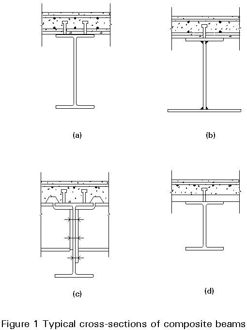
The object of this lecture is to explain the principles and rules for the design of a simply supported, i.e. single span, composite steel-concrete beam with full shear connection. Typical cross-sections of composite beams are shown in Figure 1. For simplicity, only the symmetrical steel sections 1a, 1c and 1d are considered. The relevant symbols are given in Figure 2.

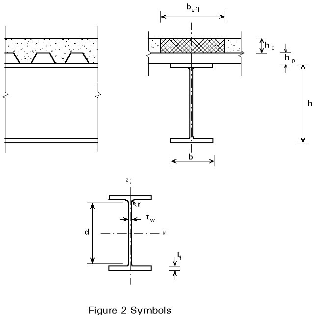
For full shear connection the total longitudinal shear resistance of the shear connectors (Rq), distributed between the point of maximum positive bending moment and a simple end support, must be greater than (or equal to) the lesser of the resistance of the steel beam (Rs = Afy/ga) when the plastic neutral axis is in the slab, or the resistance of the concrete flange (Rc = 0,85 beff hc fck/gc) when the plastic neutral axis is in the steel section.
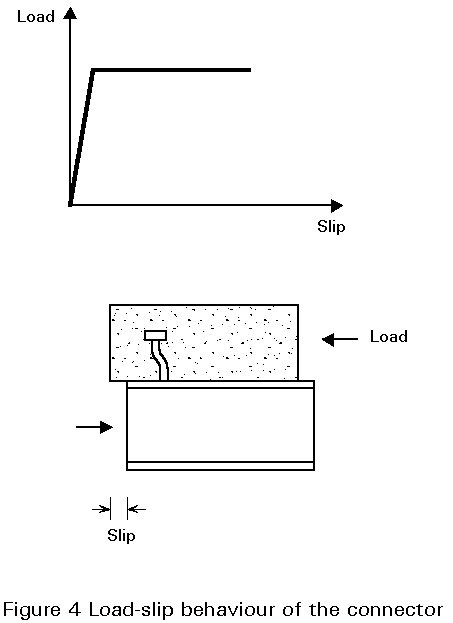
The resistance to longitudinal shear (see Figure 3, criterion III) of a shear connection is not discussed here. An idealised load-slip behaviour of the connector, as illustrated in Figure 4, is assumed; the type of shear connector which exhibits this behaviour is discussed in Lectures 10.6.1, 10.6.2 and 10.6.3.
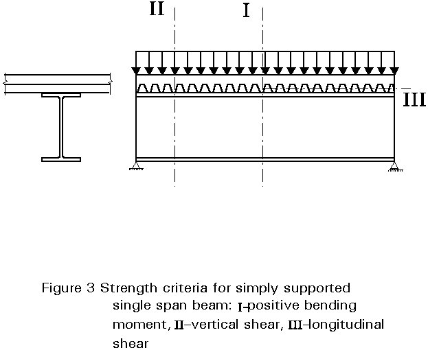
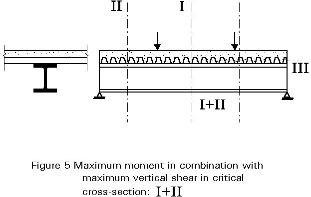
This lecture concentrates on the resistance of the beam to moment and vertical shear, which have maximum values at cross-sections I and II respectively, as shown in Figure 3). Between these critical cross-sections, each cross-section is subjected to a bending moment and a vertical shear. This combination is usually only of importance in the case where the loading includes point or line loads, as shown in Figure 5; here the maximum moment and maximum vertical shear act together at a critical cross-section adjacent to the point load or line load; special attention must be paid to this critical cross-section.
In the case of statically determinate beams, such as simply supported single span beams, it is easy to determine the distribution of bending moments from the equilibrium conditions. To determine the stress distribution over the cross-section, plastic behaviour is assumed. The advantage of this method is that the calculation of the resistance is based on the "maximum moment at failure" condition; this method is also easy to understand and apply.
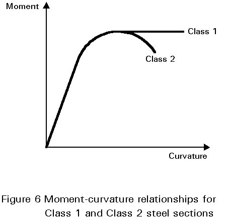
Steel sections can be classified into 4 classes depending on the local buckling behaviour of the flange and/or web in compression. In the case of a simply supported single span, plastic design methods may be used for Class 1 and 2 sections; sections of Class 2 are only allowed when no rotation capacity is required. These classes are described as follows (see also Figure 6 and Lecture 7.2):
The steel compression flange, if properly attached to the concrete flange, may be assumed to be of Class 1.
Table 1 (part of Table 4.2 of Eurocode 4 [1]), classifies steel webs in compression according to their width to thickness ratios. In a composite beam the compression part of the web, in positive bending, is always less than half the total depth for a symmetrical section. A width-to-thickness ratio less than 83e will, therefore, always be sufficient for a symmetric steel section in positive bending. Therefore, instability of the web is not critical for the IPE-sections (according to CEN-EN 19-1986) and the HE-sections (according to CEN-EN 53-1986).
Because the part in compression is always laterally restrained when the beam is in positive bending, it is not necessary to check lateral-torsional buckling (see Lecture 10.4.1 and 10.4.2). Other aspects, such as shear buckling are discussed briefly in Section 4. Web crippling, however, is beyond the scope of this lecture - see Eurocode 3 for further information [2].
For simply supported single spans, the concrete flange is in compression and cracking of the concrete is not relevant. Only deflections and vibrations are important. Lectures 10.5.1 and 10.5.2 discuss these topics.
A typical form of composite construction consists of a slab connected to a series of parallel steel members. The construction is essentially a series of interconnected T-beams with wide, thin flanges, as shown in Figure 7(a). In such a system "shear lag" may cause the flange width to be not fully effective in resisting compression [3]. This phenomenon can be explained by reference to a simply supported member, part of whose length is shown on plan in Figure 7(b).
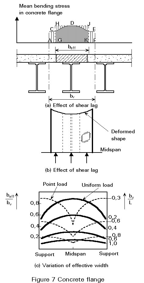
The maximum axial force in the slab is at midspan, while the force at the ends is zero. The change in longitudinal force is associated with shear in the plane of the slab. The resulting deformation, shown in Figure 7(b), is inconsistent with simple bending theory, in which initially plane sections are assumed to remain plane after bending. The edge regions of the slab are effectively less stiff, and a non-uniform distribution of longitudinal bending stress is obtained across the section. Simple theory gives an effective value for width, beff, such that the area GHJK equals the area ACDEF.
The ratio beff/bv depends not only on the relative dimensions of the system, but also on the type of loading, the support conditions and the cross-section considered; Figure 7c shows the effect of the ratio of the beam spacing to span length, bv/L, and the type of loading, on a simply supported span.
In most codes of practice very simple formulae are given for the calculation of effective widths, although this may lead to some loss of economy. According to Eurocode
4 [1], for simply supported beams, the effective width on each side of the steel web should be taken as ![]() , but not greater than half the distance to the next adjacent web, nor greater than the projection of the cantilever slab for edge beams.
, but not greater than half the distance to the next adjacent web, nor greater than the projection of the cantilever slab for edge beams.
The length lo is the approximate distance between points of zero bending moment. It is equal to the span for simply supported beams.
A constant effective width may be assumed over the whole of each span. This value may be taken as the midspan value for a beam.
In the concrete slab, a complex (three-dimensional) force distribution occurs in the region of the connector. The reason for this behaviour is that bending moments and vertical shear forces act parallel as well as perpendicular to the beam. It is difficult to find a physical design model for this complex stress distribution, and therefore, most design rules are empirical. Two design criteria can be identified:
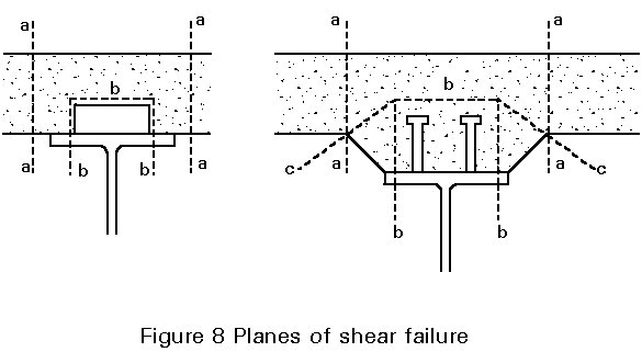
It is possible to avoid these failure modes by providing sufficient transverse reinforcement and choosing the correct distance between the connectors. In some cases, satisfying these criteria may lead to an increase in concrete slab thickness or resistance.
Longitudinal shear resistances are given in Chapter 6 of Eurocode 4 [1].
If the connectors are welded or shot fired through a continuous profiled steel sheet of a composite slab, the cross-section of the steel sheet can also be considered as transverse reinforcement.
There are design performance requirements for both the ultimate and serviceability limit states.
Ultimate Limit State
In designing a composite beam for the ultimate limit state, it is necessary to check the resistance of the critical cross-sections, and the resistance to longitudinal shear between each adjacent pair of critical cross-sections (see Figure 3). The forces and moments due to factored loads are required to be less than the design resistance. This can be expressed by:
Sd £ Rd
where
Sd is the design value of an internal force or moment
Rd is the corresponding design value of the resistance
The design value of an internal force or moment, Sd, can be determined when the static system, its geometrical data (when relevant) and the combination of the design values of the loads are known.
Characteristic values for loadings are given in Eurocode 1: Basis of Design and Actions in Structures [4]. To determine Sd, for example for criteria I of Figure 3, the characteristic permanent and variable (in this case uniformly distributed) loads must be multiplied by the corresponding g -factors and combined as follows:
Sd = (l2/8){gGSGkj + gQ(Qk1 + SQki)} (1)
which, using the values recommended in Eurocode 4 gives:
Sd = (l2/8){1,35SGkj + 1,50(Qk1 + SQki)} (2)
where
Gk,j is the characteristic value of the permanent load
Qk,l is the characteristic value of one of the variable loads
Qk,i is the characteristic value of the other variable loads.
To determine the design resistance, Rd, of members or cross-sections, the design values of the material strengths and geometrical data (when relevant) are necessary. The design value of a material property represents its lower characteristic value divided by its corresponding partial safety factor; the partial factors for material properties (and strengths) are:
|
Combination |
Structural steel |
Concrete |
Steel reinforcement |
Profiled steel sheeting |
|
Fundamental |
ga = 1,1 |
gc = 1,5 |
gs = 1,15 |
gap = 1,1 |
Other gM values, such as that for the shear connection (studs, friction grip bolts etc.) are given in Eurocode 4 [1].
The use of these material factors in determining design resistances is shown in Section 4, Equations (3) to (9), for the case of moment resistance, ie. criterion I of Figure 3.
Serviceability Limit State
In the design of a composite beam for the serviceability limit state, it must be shown that, under service conditions, the deflections and vibrations do not exceed allowable values and that cracking of the concrete is limited. The design value of the effect of loads Ed shall be less than (or equal to) a nominal value Cd (or a related function Rd):
Ed £ Cd or, Ed £ Rd
This aspect of design is discussed in greater detail in Lecture 10.5.1.
The ultimate load resistance of a simply supported beam is determined by the moment of resistance of the critical cross-section [5]. The determination of the moment of resistance of the cross-section is based on the following assumptions:
a. The shear connectors are able to transfer the forces occurring between the steel and the concrete at failure (full shear connection).
b. No slip occurs between the steel and the concrete (complete interaction).
c. Tension in concrete is neglected.
d. The strains caused by bending are directly proportional to the distance from the neutral axis; in other words, plane cross-sections remain plane after bending, even at failure.
e. The relationship between the stress sa, and the strain ea of steel is schematically represented by the diagram shown in Figure 9a.
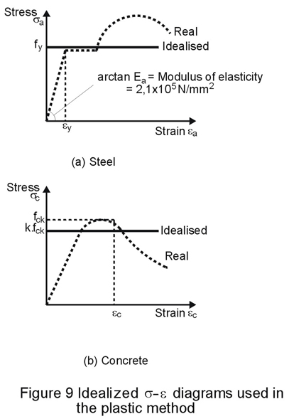
f. The relation between the stress sc and the strain ec of concrete is schematically represented by the diagram shown in Figure 9b.
Both materials are assumed to behave in a perfectly plastic manner, and therefore, the strains are not limited. This assumption is similar to that made when calculating the plastic moment resistance for Class 1 steel sections used independently. The idealised diagram for steel is shown in Figure 9a. The deviation between the real and the idealised diagram is much smaller than for concrete as shown in Figure 9b. The use of fck for the maximum stress in the concrete will clearly result in an unconservative design although in practice the overestimate does not appear to be very significant. To allow for this overestimate a conservative approximation for concrete strength (kfck) is used in design.
Experimental research has proved that the plastic method with k = 0,85, leads to a safe value for the moment of resistance. This is only true if the upper flange cross-section is less than or equal to that of the lower flange, as will usually be the case.
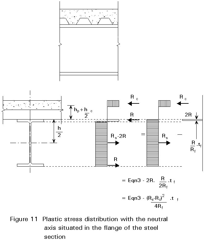
Application of these assumptions leads to the stress distributions shown in Figures 10 - 12. Clearly, the calculation of the moment of resistance Mc is dependent on the position of the neutral axis, which is determined by the relationship between the cross-section of the concrete slab and the cross-section of the steel beam. Two cases can be identified as follows:
a. the neutral axis is situated in the concrete slab:
1. in the solid part of the composite slab (Rs < Rc; see Figure 10)
2. in the rib of the composite slab (Rs= Rc)
b. the neutral axis is situated in the steel beam:
1. in the flange of the steel section (Rs > Rc > Rw; see Figure 11)
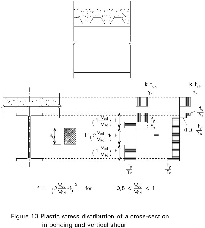
2. in the web of the steel section (Rs > Rc < Rw; see Figure 13)
The plastic moment resistance, assuming full shear connection and a symmetric steel section, is expressed in terms of the resistance of various elements of the beam as follows:
Resistance of concrete flange : Rc = beff hc 0,85 fck /gc
Resistance of steel flange : Rf = b tf fy /ga
Resistance of shear connection : Rq = N Q
Resistance of steel beam : Rs = A fy /ga
Resistance of clear web depth : Rv = d tw fy /ga
Resistance of overall web depth : Rw = Rs - 2 Rf
where
A is the area of steel beam
b is the breadth of steel flange
beff is the effective breadth of concrete flange
h is the overall depth of the steel beam
hp is the depth of profiled steel sheet
hc is the depth of concrete flange above upper flange of profiled steel sheet
d is the clear depth of web between fillets
fck is the characteristic cylinder compressive strength of the concrete
Mpl is the plastic moment resistance of steel beam
N is the number of shear connectors in shear span length between two critical cross-sections
Q is the resistance of one shear connector
tf is the thickness of steel flange
tw is the thickness of web
e
isFull shear connection applies when Rq is greater than (or equal to) the lesser of Rc and Rs.
The concrete flange is assumed to be a solid concrete slab, or a composite slab with profiled steel sheets running perpendicular to the beam. The Equations are conservative for a composite slab where the profiled steel sheets run parallel to the beam because in the resistance Rc, the concrete in the ribs is neglected.
For a composite section with full shear connection, where the steel beam has equal flanges, the plastic moment resistance Mc for positive moments is given by the following:
Case a1:
If the neutral axis is situated in the concrete flange as shown in Figure 10, Rs < Rc and the positive bending moment of resistance is:
Mpl.Rd = Rs z
where: z = h/2 + hp + hc - x/2
x = (Afy /ga) / (beff kfck /gc).hc = (Rs/Rc ).hc
Mpl.Rd = Rc (h/2 + hp + hc - Rs.hc/2Rc) (3)
Case a2:
If the neutral axis is situated in the rib of the composite slab, Rs = Rc and Equation (3) can be rewritten as:
Mpl.Rd = Rs (h + 2hp + hc)/2
or, Mpl.Rd = Rs.h/2+ Rc.(hc/2 + hp) (4)
Case b1:
If the neutral axis is situated in the steel flange, Rs > Rc > Rw. From equilibrium of normal forces it can be shown that the axial compression force R in the steel flange (see Figure 11) is:
Rc + R = Rs - 2 R + R ® 2 R = Rs - Rc ® R = (Rs - Rc)/2
This axial force R is located in the middle of the upper part of the flange, with a depth equal to: (Rtf)/Rf = (Rs - Rc).tf/2Rf . Therefore, the moment of resistance is equal to the resistance expressed by the Equation (4) minus (2R)½(Rs - Rc).tf/2Rf equal to (Rs-Rc)2.tf/4Rf as illustrated in Figure 11.
This can be written as:
Mpl.Rd = Rs.h/2+ Rc (hc/2 + hp) - (Rs - Rc)2.tf/4Rf (5)
Case b2:
If the neutral axis is in the web of the steel section, Rs > Rc < Rw. In this case, a part of the web is in compression and, as already discussed, this could influence the classification of the web.
Webs not fully effective ("non-compact webs") are not treated in this lecture. If the depth to thickness ratio of the web of a steel section is less than or equal to
83e/(1-Rc/Rv) where e = ![]() , it is considered as a compact web and the total depth is effective. The positive bending resistance is as illustrated in Figure 12:
, it is considered as a compact web and the total depth is effective. The positive bending resistance is as illustrated in Figure 12:
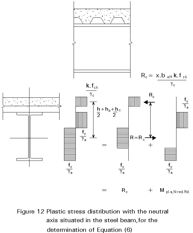
Mpl.Rd = Rc z + Mpl,N-red.Rd = Rc.(h + 2 hp + hc)/2+ Mpl,N-red.Rd (6)
where:
Mpl,N-red.Rd = plastic moment resistance of the steel beam reduced by a normal force Rc.
According to Eurocode 3 [2] the plastic moment reduced by a normal force for standard rolled I and H steel sections, can be approximated by:
Mpl,N-red.Rd = 1,11 Mpl.a.Rd (1 - Rc/Rs) £ Mpl.Rd (7)
So the resistance can be written as:
Mpl.Rd = Rc.(h + 2 hp + hc)/2 + 1,11 Mpl.a.Rd (1 - Rc/Rs) (8)
Mpl,N-red.Rd can also be written as Mpl.a.Rd - (Rc2/Rv2)(d/4)
In this case the moment of resistance is:
Mpl.Rd = Rc.(h + 2 hp + hc)/2 + Mpl.a.Rd - (Rc2/Rv2)(d/4) (9)
The formulae for the positive moment of resistance values are summarised in Table 2.
Cross-section II of Figure 3 is only subjected to vertical shear. The contribution of the concrete slab to the resistance to vertical shear is small and difficult to determine and is, therefore, neglected. Therefore, only the web of the steel section and adjacent parts of the steel flange are taken into account. The vertical shear resistance, according to Eurocode 3 [2], is given by:
Vpl,Rd = Av fy /(gaÖ3) (10)
The shear area Av, for rolled I, H and channel sections loaded parallel to the web, can be taken as: 1,04 h tw.
In addition, the shear buckling resistance of a steel web must be verified when d/tw>69e for an unstiffened (and uncased) web. For a simply-supported beam, without intermediate transverse stiffeners, with full shear connection and subjected to uniformly distributed loading, Eurocode 4 [1] gives the following simplified rules:
for ![]() w
£ 1,5 ® VRd = Vpl,Rd
(11)
w
£ 1,5 ® VRd = Vpl,Rd
(11)
for 1,5 < ![]() w< 3,0
® VRd = Vpl,Rd (3/
w< 3,0
® VRd = Vpl,Rd (3/![]() w +
1/5
w +
1/5![]() w
- 1,3) (12)
w
- 1,3) (12)
for 3,0 < ![]() w
< 4,0 ® VRd = Vpl,Rd
0,9/
w
< 4,0 ® VRd = Vpl,Rd
0,9/![]() w
(13)
w
(13)
In accordance with Eurocode 3 the web slenderness ![]() w
is given by:
w
is given by:
![]() w =
{fy/Ö3tcr}1/2
£ 4 (14)
w =
{fy/Ö3tcr}1/2
£ 4 (14)
In practice, an I-section girder has usually a transverse load bearing stiffener at the support, but no intermediate transverse stiffeners. In such a case the elastic critical shear resistance tcr is given by:
t
cr = (15)
(15)
If the factored internal force VSd, is less than Vcr = d tw tcr, the shear connectors can be uniformly distributed; if not, more connectors should be placed near the support.
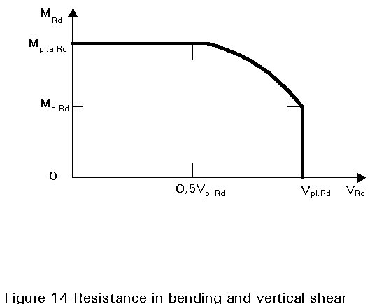
Where the vertical shear VSd exceeds half the plastic shear resistance Vpl.Rd given by Equation (10) due allowance shall be made for its effect on the plastic moment of resistance. This is of importance at cross-section (I+II) of Figure 5, where both load effects, vertical shear and bending, are at a maximum. The following methods are used for such cases:
Rs,red = Rs - (2VSd/VRd - 1) Vpl.Rd for: 0,5 < VSd/VRd £ 1 (16)
In this case, part of the middle of the web of the steel section, is reserved to resist the vertical shear. The depth of this part of the web is
(2VSd/VRd - 1) h
providing a depth equal to zero when VSd/VRd = 0.5 and equal to h where VSd/VRd = 1,0
The part of the web that is reserved for vertical shear is located in the middle of the web depth. The section modulus of the web will, therefore, be reduced by:
¼tw ( (2VSd/VRd - 1) h)2 for 0,5 < VSd/VRd £ 1 (17)
which becomes:
¼tw h2 (1 - (2VSd/VRd - 1)2 ) (18)
If the factor r is assumed to be equal to (2VSd/VRd - 1)2 the section modulus of the web can also be written as:
¼tw h2 (1 - r )
In other words, it is possible to take into account the vertical shear by reducing the design yield stress in the web by a factor (1 - r) for the area Av (1 - do/d) where do is the depth of web neglected when calculating Mpl.Rd. The plastic moment of resistance reduced by vertical shear can be expressed approximately by:
Mpl,V-red.Rd = {1 - r(1 - do/d).A/(2A - Av)}.Mpl.Rd (19)
These rules are shown in Figure 14 in which Mpl.Rd is the plastic moment of resistance when r = 1.
[1] Eurocode 4: "Design of Composite Steel and Concrete Structures": ENV1994-1-1: Part 1.1: General rules and rules for buildings, CEN (in press).
[2] Eurocode 3: "Design of Steel Structures": ENV1993-1-1: Part 1.1: General rules and rules for buildings, CEN, 1992.
[3] Dowling, P. J., Knowles, Owens, G., "Structural Steel Design", Steel Construction Institute, 1988 (UK).
[4] Eurocode 1: "Basis of Design and Actions on Structures", CEN (in preparation).
[5] Stark, J.W.B., van Hove, B. W. E., "Composite Steel and Concrete Beams with Partial Shear Connection", HERON, TNO-Building and Construction Research/TU-Delft publication, 2nd quarter 1990 (UK).
Table 1 Maximum width-to-thickness ratios for steel webs
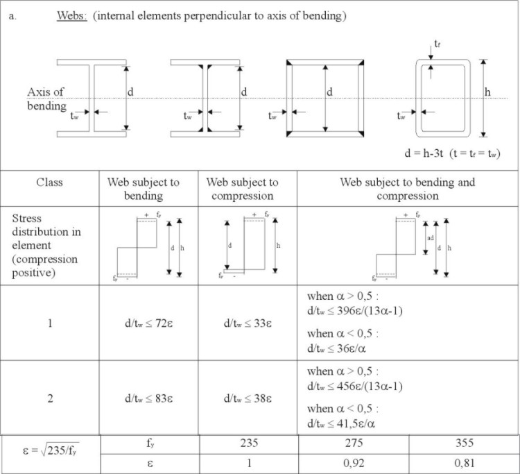
Table 2 Positive moment of resistance values
|
Rs < Rc |
|
|
Rs = Rc |
|
|
Rs > Rc > Rw |
|
|
Rs > Rc < Rw
and compact webs |
OR:
|